- Index
- Preface
- Product Overview
- Command-Line Interfaces
- Configuring the Switch for the First Time
- Configuring Interfaces
- Checking Port Status and Connectivity
- Configuring Supervisor Engine Redundancy using RPR and SSO
- Environmental Monitoring and Power Management
- Configuring Power over Ethernet
- Managing a Network of Switches
- Understanding and Configuring VLANs
- Configuring Dynamic VLAN Membership
- Configuring Layer 2 Ethernet Interfaces
- Configuring SmartPort Macros
- Understanding and Configuring STP
- Configuring STP Features
- Understanding and Configuring Multiple Spanning Trees
- Understanding and Configuring EtherChannel
- Configuring IGMP Snooping and Filtering
- Configuring 802.1Q and Layer 2 Protocol Tunneling
- Understanding and Configuring CDP
- Configuring UDLD
- Configuring Unidirectional Ethernet
- Configuring Layer 3 Interfaces
- Configuring Cisco Express Forwarding
- Understanding and Configuring IP Multicast
- Configuring Policy-Based Routing
- Understanding and Configuring VTP
- Configuring VRF-lite
- Configuring QoS
- Configuring Voice Interfaces
- Understanding and Configuring 802.1X Port-Based Authentication
- Configuring Port Security
- Configuring DHCP Snooping and IP Source Guard
- Understanding and Configuring Dynamic ARP Inspection
- Configuring Network Security with ACLs
- Configuring Private VLANs
- Port Unicast and Multicast Flood Blocking
- Configuring Port-Based Traffic Control
- Configuring SPAN and RSPAN
- Configuring NetFlow Statistics Collection
- Acronyms
- Understanding ACLs
- Hardware and Software ACL Support
- TCAM Programming and ACLs
- Layer 4 Operators in ACLs
- Configuring Unicast MAC Address Filtering
- Configuring Named MAC Extended ACLs
- Configuring VLAN Maps
Configuring Network Security with ACLs
This chapter describes how to use access control lists (ACLs) to configure network security on the Catalyst 4500 series switches.

Note ![]() For complete syntax and usage information for the switch commands used in this chapter, refer to the Catalyst 4500 Series Switch Cisco IOS Command Reference and related publications at
For complete syntax and usage information for the switch commands used in this chapter, refer to the Catalyst 4500 Series Switch Cisco IOS Command Reference and related publications at
http://www.cisco.com/univercd/cc/td/doc/product/software/ios122/122cgcr/index.htm.
This chapter consists of the following major sections:
•![]() Hardware and Software ACL Support
Hardware and Software ACL Support
•![]() Configuring Unicast MAC Address Filtering
Configuring Unicast MAC Address Filtering
•![]() Configuring Named MAC Extended ACLs
Configuring Named MAC Extended ACLs
•![]() Displaying VLAN Access Map Information
Displaying VLAN Access Map Information
•![]() Using VLAN Maps with Router ACLs
Using VLAN Maps with Router ACLs
•![]() Using PACL with VLAN Maps and Router ACLs
Using PACL with VLAN Maps and Router ACLs
Understanding ACLs
This section contains the following subsections:
•![]() Supported Features That Use ACLs
Supported Features That Use ACLs
ACL Overview
An ACL is a collection of sequential permit and deny conditions that applies to packets. When a packet is received on an interface, the switch compares the fields in the packet against any applied ACLs to verify that the packet has the permissions required to be forwarded, based on the conditions specified in the access lists. It tests the packets against the conditions in an access list one-by-one. The first match determines whether the switch accepts or rejects the packets. Because the switch stops testing conditions after the first match, the order of conditions in the list is critical. If no conditions match, the switch drops the packet. If there are no restrictions, the switch forwards the packet; otherwise, the switch drops the packet.
Switches traditionally operate at Layer 2, switching traffic within a VLAN, whereas routers route traffic between VLANs at Layer 3. The Catalyst 4500 series switch can accelerate packet routing between VLANs by using Layer 3 switching. The Layer 3 switch bridges the packet, and then routed the packet internally without going to an external router. The packet is then bridged again and sent to its destination. During this process, the switch can control all packets, including packets bridged within a VLAN.
You configure access lists on a router or switch to filter traffic and provide basic security for your network. If you do not configure ACLs, all packets passing through the switch could be allowed on all parts of the network. You can use ACLs to control which hosts can access different parts of a network or to decide which types of traffic are forwarded or blocked at router interfaces. For example, you can allow e-mail traffic to be forwarded but not Telnet traffic. ACLs can be configured to block inbound traffic, outbound traffic, or both. However, on Layer 2 interfaces, you can apply ACLs only in the inbound direction.
An ACL contains an ordered list of access control entries (ACEs). Each ACE specifies permit or deny and a set of conditions the packet must satisfy in order to match the ACE. The meaning of permit or deny depends on the context in which the ACL is used.
The Catalyst 4500 series switch supports two types of ACLs:
•![]() IP ACLs, which filter IP traffic, including TCP, the User Datagram Protocol (UDP), Internet Group Management Protocol (IGMP), and Internet Control Message Protocol (ICMP).
IP ACLs, which filter IP traffic, including TCP, the User Datagram Protocol (UDP), Internet Group Management Protocol (IGMP), and Internet Control Message Protocol (ICMP).
•![]() MAC (Ethernet) ACLs, which filter non-IP traffic.
MAC (Ethernet) ACLs, which filter non-IP traffic.
Supported Features That Use ACLs
The switch supports two applications of ACLs to filter traffic:
•![]() Router ACLs are applied to Layer 3 interfaces. They control the access of routed traffic between VLANs. All Catalyst 4500 series switches can create router ACLs, but you must have a Cisco IOS software image on your switch to apply an ACL to a Layer 3 interface and filter packets routed between VLANs.
Router ACLs are applied to Layer 3 interfaces. They control the access of routed traffic between VLANs. All Catalyst 4500 series switches can create router ACLs, but you must have a Cisco IOS software image on your switch to apply an ACL to a Layer 3 interface and filter packets routed between VLANs.
•![]() Port ACLs perform access control on traffic entering a Layer 2 interface. If there are not enough hardware CAM entries, the output port ACL is not applied to the port and a warning message is given to user. (This restriction applies to all access group modes for output port ACLs.) When there are enough CAM entries, the output port ACL might be reapplied.
Port ACLs perform access control on traffic entering a Layer 2 interface. If there are not enough hardware CAM entries, the output port ACL is not applied to the port and a warning message is given to user. (This restriction applies to all access group modes for output port ACLs.) When there are enough CAM entries, the output port ACL might be reapplied.
If there is any output port ACL configured on a Layer 2 port, then no VACL or router ACL can be configured on the VLANs that the Layer 2 port belongs to. Also, the reverse is true: port ACLs and VLAN-based ACLs (VACLs and router ACLs) are mutually exclusive on a Layer 2 port. This restriction applies to all access group modes.
You can apply only one IP access list and one MAC access list to a Layer 2 interface.
•![]() VLAN ACLs or VLAN maps control the access of all packets (bridged and routed). You can use VLAN maps to filter traffic between devices in the same VLAN. You do not need the enhanced image to create or apply VLAN maps. VLAN maps are configured to control access based on Layer 3 addresses for IP. MAC addresses using Ethernet ACEs control the access of unsupported protocols. After you apply a VLAN map to a VLAN, all packets (routed or bridged) entering the VLAN are checked against that map. Packets can either enter the VLAN through a switch port or through a routed port after being routed.
VLAN ACLs or VLAN maps control the access of all packets (bridged and routed). You can use VLAN maps to filter traffic between devices in the same VLAN. You do not need the enhanced image to create or apply VLAN maps. VLAN maps are configured to control access based on Layer 3 addresses for IP. MAC addresses using Ethernet ACEs control the access of unsupported protocols. After you apply a VLAN map to a VLAN, all packets (routed or bridged) entering the VLAN are checked against that map. Packets can either enter the VLAN through a switch port or through a routed port after being routed.
You can use both router ACLs and VLAN maps on the same switch.
Router ACLs
You can apply router ACLs on switch virtual interfaces (SVIs), which are Layer 3 interfaces to VLANs; on physical Layer 3 interfaces; and on Layer 3 EtherChannel interfaces. Router ACLs are applied on interfaces for specific directions (inbound or outbound). You can apply one IP access list in each direction.
Multiple features can use one ACL for a given interface, and one feature can use multiple ACLs. When a single router ACL is used by multiple features, it is examined multiple times. The access list type determines the input to the matching operation:
•![]() Standard IP access lists use source addresses for matching operations.
Standard IP access lists use source addresses for matching operations.
•![]() Extended IP access lists use source and destination addresses and optional protocol type information for matching operations.
Extended IP access lists use source and destination addresses and optional protocol type information for matching operations.
The switch examines ACLs associated with features configured on a given interface and a direction. As packets enter the switch on an interface, ACLs associated with all inbound features configured on that interface are examined. After packets are routed and before they are forwarded to the next hop, all ACLs associated with outbound features configured on the egress interface are examined.
ACLs permit or deny packet forwarding based on how the packet matches the entries in the ACL. For example, you can use access lists to allow one host to access a part of a network, but prevent another host from accessing the same part. In Figure 35-1, ACLs applied at the router input allow Host A to access the Human Resources network, but prevent Host B from accessing the same network.
Figure 35-1 Using ACLs to Control Traffic to a Network

Port ACLs
You can also apply ACLs to Layer 2 interfaces on a switch. Port ACLs are supported on physical interfaces and EtherChannel interfaces.
The following access lists are supported on Layer 2 interfaces:
•![]() Standard IP access lists using source addresses
Standard IP access lists using source addresses
•![]() Extended IP access lists using source and destination addresses and optional protocol type information
Extended IP access lists using source and destination addresses and optional protocol type information
•![]() MAC extended access lists using source and destination MAC addresses and optional protocol type information
MAC extended access lists using source and destination MAC addresses and optional protocol type information
As with router ACLs, the switch examines ACLs associated with features configured on a given interface and permits or denies packet forwarding based on how the packet matches the entries in the ACL. In the example in Figure 35-1, if all workstations were in the same VLAN, ACLs applied at the Layer 2 input would allow Host A to access the Human Resources network, but prevent Host B from accessing the same network.
When you apply a port ACL to a trunk port, the ACL filters traffic on all VLANs present on the trunk port. When you apply a port ACL to a port with voice VLAN, the ACL filters traffic on both data and voice VLANs.
With port ACLs, you can filter IP traffic by using IP access lists and non-IP traffic by using MAC addresses. You can filter both IP and non-IP traffic on the same Layer 2 interface by applying both an IP access list and a MAC access list to the interface.
Note ![]() You cannot apply more than one IP access list and one MAC access list to a Layer 2 interface. If an IP access list or MAC access list is already configured on a Layer 2 interface and you apply a new IP access list or MAC access list to the interface, the new ACL replaces the previously configured one.
You cannot apply more than one IP access list and one MAC access list to a Layer 2 interface. If an IP access list or MAC access list is already configured on a Layer 2 interface and you apply a new IP access list or MAC access list to the interface, the new ACL replaces the previously configured one.
VLAN Maps
VLAN maps can control the access of all traffic in a VLAN. You can apply VLAN maps on the switch to all packets that are routed into or out of a VLAN or are bridged within a VLAN. Unlike router ACLs, VLAN maps are not defined by direction (input or output).
You can configure VLAN maps to match Layer 3 addresses for IP traffic. Access of all non-IP protocols is controlled with a MAC address and an Ethertype using MAC ACLs in VLAN maps. (IP traffic is not controlled by MAC ACLs in VLAN maps.) You can enforce VLAN maps only on packets going through the switch; you cannot enforce VLAN maps on traffic between hosts on a hub or on another switch connected to this switch.
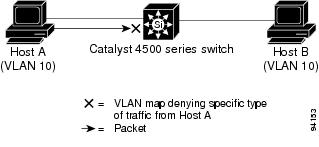
With VLAN maps, forwarding packets is permitted or denied, based on the action specified in the map. Figure 35-2 illustrates how a VLAN map is applied to deny a specific type of traffic from Host A in VLAN 10 from being forwarded.
Figure 35-2 Using VLAN Maps to Control Traffic
Hardware and Software ACL Support
This section describes how to determine whether ACLs are processed in hardware or in software:
•![]() Flows that match a deny statement in standard and extended ACLs (input only) are dropped in hardware if ICMP unreachable messages are disabled.
Flows that match a deny statement in standard and extended ACLs (input only) are dropped in hardware if ICMP unreachable messages are disabled.
•![]() Flows that match a permit statement in standard and extended ACLs (input and output) are processed in hardware.
Flows that match a permit statement in standard and extended ACLs (input and output) are processed in hardware.
•![]() The following ACL types are not supported in software:
The following ACL types are not supported in software:
–![]() Standard Xerox Network Systems (XNS) Protocol access list
Standard Xerox Network Systems (XNS) Protocol access list
–![]() Extended XNS access list
Extended XNS access list
–![]() DECnet access list
DECnet access list
–![]() Protocol type-code access list
Protocol type-code access list
–![]() Standard Internet Packet Exchange (IPX) access list
Standard Internet Packet Exchange (IPX) access list
–![]() Extended IPX access list
Extended IPX access list
Note ![]() Packets that require logging are processed in software. A copy of the packets is sent to the CPU for logging while the actual packets are forwarded in hardware so that non-logged packet processing is not impacted.
Packets that require logging are processed in software. A copy of the packets is sent to the CPU for logging while the actual packets are forwarded in hardware so that non-logged packet processing is not impacted.
By default, the Catalyst 4500 series switch sends ICMP unreachable messages when a packet is denied by an access list; these packets are not dropped in hardware but are forwarded to the switch so that it can generate the ICMP unreachable message.
To drop access-list denied packets in hardware on the input interface, you must disable ICMP unreachable messages using the no ip unreachables interface configuration command. The ip unreachables command is enabled by default.
Packets denied by an output access list are always forwarded to the CPU.
TCAM Programming and ACLs
Two types of hardware resources are consumed when you program ACLs: entries and masks. If one of these resources is exhausted, no additional ACLs can be programmed into hardware. If the masks on a system are exhausted, but entries are available, changing the programming scheme from packed to scattered might free up masks, allowing additional ACLs to be programmed into hardware.
The goal is to use TCAM resources more efficiently by minimizing the number of masks per ACL entries. To compare TCAM utilization when employing the scattered or packed algorithms, use the
show platform hardware acl statistics utilization brief command. To change the algorithm from packed to scattered, use the access-list hardware entries command. To disable an algorithm, use the no acccess-list hardware entries command.
Note ![]() To determine whether the packed algorithm is configured, use the show running config command. If packed is configured, the line access-list hardware entries packed will appear.
To determine whether the packed algorithm is configured, use the show running config command. If packed is configured, the line access-list hardware entries packed will appear.
Note ![]() The default TCAM programming algorithm is packed.
The default TCAM programming algorithm is packed.
The following output was collected from a switch running in packed mode. Observe that 89 percent of the masks are required to program only 49 percent of the ACL entries.
Switch# configure terminal
Enter configuration commands, one per line. End with CNTL/Z.
Switch(config)# access-list hardware entries packed
Switch(config)# end
Switch#
01:15:34: %SYS-5-CONFIG_I: Configured from console by console
Switch#
Switch# show platform hardware acl statistics utilization brief
Entries/Total(%) Masks/Total(%)
----------------- ---------------
Input Acl(PortAndVlan) 2016 / 4096 ( 49) 460 / 512 ( 89)
Input Acl(PortOrVlan) 6 / 4096 ( 0) 4 / 512 ( 0)
Input Qos(PortAndVlan) 0 / 4096 ( 0) 0 / 512 ( 0)
Input Qos(PortOrVlan) 0 / 4096 ( 0) 0 / 512 ( 0)
Output Acl(PortAndVlan) 0 / 4096 ( 0) 0 / 512 ( 0)
Output Acl(PortOrVlan) 0 / 4096 ( 0) 0 / 512 ( 0)
Output Qos(PortAndVlan) 0 / 4096 ( 0) 0 / 512 ( 0)
Output Qos(PortOrVlan) 0 / 4096 ( 0) 0 / 512 ( 0)
L4Ops: used 2 out of 64
The following output was collected after the algorithm was switched to scattered. Observe that the
number of masks required to program 49 percent of the entries has decreased to 49 percent.
Note ![]() When you enable DHCP snooping and IP Source Guard on all ports on a chassis, you must use the scattered keyword.
When you enable DHCP snooping and IP Source Guard on all ports on a chassis, you must use the scattered keyword.
Switch# configure terminal
Enter configuration commands, one per line. End with CNTL/Z.
Switch(config)# access-list hardware entries scattered
Switch(config)# end
Switch#
01:39:37: %SYS-5-CONFIG_I: Configured from console by console
Switch#
Switch# show platform hardware acl statistics utilization brief
Entries/Total(%) Masks/Total(%)
----------------- ---------------
Input Acl(PortAndVlan) 2016 / 4096 ( 49) 252 / 512 ( 49)
Input Acl(PortOrVlan) 6 / 4096 ( 0) 5 / 512 ( 0)
Input Qos(PortAndVlan) 0 / 4096 ( 0) 0 / 512 ( 0)
Input Qos(PortOrVlan) 0 / 4096 ( 0) 0 / 512 ( 0)
Output Acl(PortAndVlan) 0 / 4096 ( 0) 0 / 512 ( 0)
Output Acl(PortOrVlan) 0 / 4096 ( 0) 0 / 512 ( 0)
Output Qos(PortAndVlan) 0 / 4096 ( 0) 0 / 512 ( 0)
Output Qos(PortOrVlan) 0 / 4096 ( 0) 0 / 512 ( 0)
L4Ops: used 2 out of 64
Switch#
Layer 4 Operators in ACLs
The following sections describe guidelines and restrictions for configuring ACLs that include Layer 4 port operations:
•![]() Restrictions for Layer 4 Operations
Restrictions for Layer 4 Operations
•![]() Configuration Guidelines for Layer 4 Operations
Configuration Guidelines for Layer 4 Operations
•![]() How ACL Processing Impacts CPU
How ACL Processing Impacts CPU
Restrictions for Layer 4 Operations
You can specify these operator types, each of which uses one Layer 4 operation in the hardware:
•![]() gt (greater than)
gt (greater than)
•![]() lt (less than)
lt (less than)
•![]() neq (not equal)
neq (not equal)
•![]() range (inclusive range)
range (inclusive range)
We recommend that you not specify more than six different operations on the same ACL. If you exceed this number, each new operation might cause the affected ACE (access control entry) to be translated into multiple ACEs in hardware. If you exceed this number, the affected ACE might be processed in software.
Configuration Guidelines for Layer 4 Operations
Keep the following guidelines in mind when using Layer 4 operators:
•![]() Layer 4 operations are considered different if the operator or operand differ. For example, the following ACL contains three different Layer 4 operations because gt 10 and gt 11 are considered two different Layer 4 operations:
Layer 4 operations are considered different if the operator or operand differ. For example, the following ACL contains three different Layer 4 operations because gt 10 and gt 11 are considered two different Layer 4 operations:
... gt 10 permit
... lt 9 deny
... gt 11 deny
Note ![]() The eq operator can be used an unlimited number of times because eq does not use a Layer 4 operation in hardware.
The eq operator can be used an unlimited number of times because eq does not use a Layer 4 operation in hardware.
•![]() Layer 4 operations are considered different if the same operator/operand couple applies once to a source port and once to a destination port, as in the following example:
Layer 4 operations are considered different if the same operator/operand couple applies once to a source port and once to a destination port, as in the following example:
... Src gt 10....
... Dst gt 10
A more detailed example follows:
access-list 101
... (dst port) gt 10 permit
... (dst port) lt 9 deny
... (dst port) gt 11 deny
... (dst port) neq 6 permit
... (src port) neq 6 deny
... (dst port) gt 10 deny
access-list 102
... (dst port) gt 20 deny
... (src port) lt 9 deny
... (src port) range 11 13 deny
... (dst port) neq 6 permit
Access lists 101 and 102 use the following Layer 4 operations:
•![]() Access list 101 Layer 4 operations: 5
Access list 101 Layer 4 operations: 5
–![]() gt 10 permit and gt 10 deny both use the same operation because they are identical and both operate on the destination port.
gt 10 permit and gt 10 deny both use the same operation because they are identical and both operate on the destination port.
•![]() Access list 102 Layer 4 operations: 4
Access list 102 Layer 4 operations: 4
•![]() Total Layer 4 operations: 8 (due to sharing between the two access lists)
Total Layer 4 operations: 8 (due to sharing between the two access lists)
–![]() neg6 permit is shared between the two ACLs because they are identical and both operate on the same destination port.
neg6 permit is shared between the two ACLs because they are identical and both operate on the same destination port.
•![]() A description of the Layer 4 operations usage is as follows:
A description of the Layer 4 operations usage is as follows:
–![]() Layer 4 operation 1 stores gt 10 permit and gt 10 deny from ACL 101
Layer 4 operation 1 stores gt 10 permit and gt 10 deny from ACL 101
–![]() Layer 4 operation 2 stores lt 9 deny from ACL 101
Layer 4 operation 2 stores lt 9 deny from ACL 101
–![]() Layer 4 operation 3 stores gt 11 deny from ACL 101
Layer 4 operation 3 stores gt 11 deny from ACL 101
–![]() Layer 4 operation 4 stores neg 6 permit from ACL 101 and 102
Layer 4 operation 4 stores neg 6 permit from ACL 101 and 102
–![]() Layer 4 operation 5 stores neg 6 deny from ACL 101
Layer 4 operation 5 stores neg 6 deny from ACL 101
–![]() Layer 4 operation 6 stores gt 20 deny from ACL 102
Layer 4 operation 6 stores gt 20 deny from ACL 102
–![]() Layer 4 operation 7 stores lt 9 deny from ACL 102
Layer 4 operation 7 stores lt 9 deny from ACL 102
–![]() Layer 4 operation 8 stores range 11 13 deny from ACL 102
Layer 4 operation 8 stores range 11 13 deny from ACL 102
How ACL Processing Impacts CPU
ACL processing can impact the CPU in two ways:
•![]() For some packets, when the hardware runs out of resources, the software must perform the ACL matches:
For some packets, when the hardware runs out of resources, the software must perform the ACL matches:
–![]() TCP flag combinations other than rst ack and syn fin rst are processed in software. rst ack is equivalent to the keyword established.
TCP flag combinations other than rst ack and syn fin rst are processed in software. rst ack is equivalent to the keyword established.
–![]() You can specify up to six Layer 4 operations (lt, gt, neq, and range) in an ACL in order for all operations to be guaranteed to be processed in hardware. More than six Layer 4 operations will trigger an attempt to translate the excess operations into multiple ACEs in hardware. If this attempt fails, packets will be processed in software. The translation process is less likely to succeed on large ACLs with a great number of Layer 4 operations, and on switches with large numbers of ACLs configured. The precise limit depends on how many other ACLs are configured and which specific Layer 4 operations are used by the ACLs being translated. The eq operator does not require any Layer 4 operations and can be used any number of times.
You can specify up to six Layer 4 operations (lt, gt, neq, and range) in an ACL in order for all operations to be guaranteed to be processed in hardware. More than six Layer 4 operations will trigger an attempt to translate the excess operations into multiple ACEs in hardware. If this attempt fails, packets will be processed in software. The translation process is less likely to succeed on large ACLs with a great number of Layer 4 operations, and on switches with large numbers of ACLs configured. The precise limit depends on how many other ACLs are configured and which specific Layer 4 operations are used by the ACLs being translated. The eq operator does not require any Layer 4 operations and can be used any number of times.
–![]() If the total number of Layer 4 operations in an ACL is less than six, you can distribute the operations in any way you choose.
If the total number of Layer 4 operations in an ACL is less than six, you can distribute the operations in any way you choose.
Examples:
The following access lists will be processed completely in hardware:
access-list 104 permit tcp any any established
access-list 105 permit tcp any any rst ack
access-list 107 permit tcp any synfin rst
Access lists 104 and 105 are identical; established is shorthand for rst and ack.
Access list 101, below, will be processed completely in software:
access-list 101 permit tcp any any urg
Because four source and two destination operations exist, access list 106, below, will be processed in hardware:
access-list 106 permit tcp any range 100 120 any range 120 140
access-list 106 permit tcp any range 140 160 any range 180 200
access-list 106 permit tcp any range 200 220
access-list 106 deny tcp any range 220 240
In the following code, the Layer 4 operations for the third ACE will trigger an attempt to translate dst lt 1023 into multiple ACEs in hardware, because three source and three destination operations exist. If the translation attempt fails, the third ACE will be processed in software.
access-list 102 permit tcp any lt 80 any gt 100
access-list 102 permit tcp any range 100 120 any range 120 1024
access-list 102 permit tcp any gt 1024 any lt 1023
Similarly, for access list 103, below, the third ACE will trigger an attempt to translate dst gt 1023 into multiple ACEs in hardware. If the attempt fails, the third ACE will be processed in software. Although the operations for source and destination ports look similar, they are considered different Layer 4 operations.)
access-list 103 permit tcp any lt 80 any lt 80
access-list 103 permit tcp any range 100 120 any range 100 120
access-list 103 permit tcp any gt 1024 any gt 1023
Note ![]() Remember that source port lt 80 and destination port lt 80 are considered different operations.
Remember that source port lt 80 and destination port lt 80 are considered different operations.
•![]() Some packets must be sent to the CPU for accounting purposes, but the action is still performed by the hardware. For example, if a packet must be logged, a copy is sent to the CPU for logging, but the forwarding (or dropping) is performed in the hardware. Although logging slows the CPU, it does not affect the forwarding rate. This sequence of events would happen under the following conditions:
Some packets must be sent to the CPU for accounting purposes, but the action is still performed by the hardware. For example, if a packet must be logged, a copy is sent to the CPU for logging, but the forwarding (or dropping) is performed in the hardware. Although logging slows the CPU, it does not affect the forwarding rate. This sequence of events would happen under the following conditions:
–![]() When a log keyword is used
When a log keyword is used
–![]() When an output ACL denies a packet
When an output ACL denies a packet
–![]() When an input ACL denies a packet, and on the interface where the ACL is applied, ip unreachable is enabled (ip unreachable is enabled by default on all the interfaces)
When an input ACL denies a packet, and on the interface where the ACL is applied, ip unreachable is enabled (ip unreachable is enabled by default on all the interfaces)
Configuring Unicast MAC Address Filtering
To block all unicast traffic to or from a MAC address in a specified VLAN, perform this task:
This example shows how to block all unicast traffic to or from MAC address 0050.3e8d.6400 in VLAN 12:
Router# configure terminal
Router(config)# mac-address-table static 0050.3e8d.6400 vlan 12 drop
Configuring Named MAC Extended ACLs
You can filter non-IP traffic on a VLAN and on a physical Layer 2 port by using MAC addresses and named MAC extended ACLs. The procedure is similar to that of configuring other extended named ACLs. You can use a number to name the access list, but MAC access list numbers from 700 to 799 are not supported.
Note ![]() Named MAC extended ACLs cannot be applied to Layer 3 interfaces.
Named MAC extended ACLs cannot be applied to Layer 3 interfaces.
For more information about the supported non-IP protocols in the mac access-list extended command, refer to the Catalyst 4500 Series Switch Cisco IOS Command Reference.
To create a named MAC extended ACL, perform this task:
You can use the no mac access-list extended name global configuration command to delete the entire ACL. You can also delete individual ACEs from named MAC extended ACLs.
This example shows how to create and display an access list named mac1, denying only EtherType DECnet Phase IV traffic, but permitting all other types of traffic.
Switch(config)# mac access-list extended mac1
Switch(config-ext-macl)# deny any any decnet-iv (old) protocol-family decnet (new)
Switch(config-ext-macl)# permit any any
Switch(config-ext-macl)# end
Switch # show access-lists
Extended MAC access list mac1
deny any any decnet-iv (old) protocol-family decnet (new)
permit any any
Configuring VLAN Maps
This section contains the following subsections:
•![]() VLAN Map Configuration Guidelines
VLAN Map Configuration Guidelines
•![]() Creating and Deleting VLAN Maps
Creating and Deleting VLAN Maps
•![]() Applying a VLAN Map to a VLAN
Applying a VLAN Map to a VLAN
•![]() Using VLAN Maps in Your Network
Using VLAN Maps in Your Network
This section describes how to configure VLAN maps, which is the only way to control filtering within a VLAN. VLAN maps have no direction. To filter traffic in a specific direction by using a VLAN map, you need to include an ACL with specific source or destination addresses. If there is a match clause for that type of packet (IP or MAC) in the VLAN map, the default action is to drop the packet if the packet does not match any of the entries within the map. If there is no match clause for that type of packet, the default is to forward the packet.
To create a VLAN map and apply it to one or more VLANs, perform this task
Step 1 ![]() Create the standard or extended IP ACLs or named MAC extended ACLs that you want to apply to the VLAN.
Create the standard or extended IP ACLs or named MAC extended ACLs that you want to apply to the VLAN.
Step 2 ![]() Enter the vlan access-map global configuration command to create a VLAN ACL map entry.
Enter the vlan access-map global configuration command to create a VLAN ACL map entry.
Step 3 ![]() In access map configuration mode, you have the optional to enter an action (forward [the default] or drop) and enter the match command to specify an IP packet or a non-IP packet and to match the packet against one or more ACLs (standard or extended). If a match clause is not specified, the action is applied to all packets. The match clause can be used to match against multiple ACLs. If a packet matches any of the specified ACLs, the action is applied.
In access map configuration mode, you have the optional to enter an action (forward [the default] or drop) and enter the match command to specify an IP packet or a non-IP packet and to match the packet against one or more ACLs (standard or extended). If a match clause is not specified, the action is applied to all packets. The match clause can be used to match against multiple ACLs. If a packet matches any of the specified ACLs, the action is applied.
Note ![]() If the VLAN map has a match clause for the type of packet (IP or MAC) and the packet does not match the type, the default is to drop the packet. If there is no match clause in the VLAN map for that type of packet, and no action specified, the packet is forwarded.
If the VLAN map has a match clause for the type of packet (IP or MAC) and the packet does not match the type, the default is to drop the packet. If there is no match clause in the VLAN map for that type of packet, and no action specified, the packet is forwarded.
Step 4 ![]() Use the vlan filter global configuration command to apply a VLAN map to one or more VLANs.
Use the vlan filter global configuration command to apply a VLAN map to one or more VLANs.
Note ![]() You cannot apply a VLAN map to a VLAN on a switch that has ACLs applied to Layer 2 interfaces (port ACLs).
You cannot apply a VLAN map to a VLAN on a switch that has ACLs applied to Layer 2 interfaces (port ACLs).
VLAN Map Configuration Guidelines
Keep the following guidelines in mind when configuring VLAN maps:
•![]() VLAN maps do not filter IPv4 ARP packets.
VLAN maps do not filter IPv4 ARP packets.
•![]() If there is no router ACL configured to deny traffic on a routed VLAN interface (input or output), and no VLAN map configured, all traffic is permitted.
If there is no router ACL configured to deny traffic on a routed VLAN interface (input or output), and no VLAN map configured, all traffic is permitted.
•![]() Each VLAN map consists of a series of entries. The order of entries in a VLAN map is important. A packet that comes into the switch is tested against the first entry in the VLAN map. If it matches, the action specified for that part of the VLAN map is taken. If there is no match, the packet is tested against the next entry in the map.
Each VLAN map consists of a series of entries. The order of entries in a VLAN map is important. A packet that comes into the switch is tested against the first entry in the VLAN map. If it matches, the action specified for that part of the VLAN map is taken. If there is no match, the packet is tested against the next entry in the map.
•![]() If the VLAN map has at least one match clause for the type of packet (IP or MAC) and the packet does not match any of these match clauses, the default is to drop the packet. If there is no match clause for that type of packet in the VLAN map, the default is to forward the packet.
If the VLAN map has at least one match clause for the type of packet (IP or MAC) and the packet does not match any of these match clauses, the default is to drop the packet. If there is no match clause for that type of packet in the VLAN map, the default is to forward the packet.
•![]() The system might take longer to boot if you have configured a very large number of ACLs.
The system might take longer to boot if you have configured a very large number of ACLs.
Creating and Deleting VLAN Maps
Each VLAN map consists of an ordered series of entries. To create, add to, or delete a VLAN map entry, perform this task:
You can use the no vlan access-map name global configuration command to delete a map. You can use the no vlan access-map name number global configuration command to delete a single sequence entry from within the map. You can use the no action access-map configuration command to enforce the default action, which is to forward.
VLAN maps do not use the specific permit or deny keywords. To deny a packet by using VLAN maps, create an ACL that would match the packet, and then set the action to drop. A permit in the ACL is the same as a match. A deny in the ACL means no match.
Examples of ACLs and VLAN Maps
These examples show how to create ACLs and VLAN maps that for specific purposes.
Example 1
This example shows how to create an ACL and a VLAN map to deny a packet. In the first map, any packets that match the ip1 ACL (TCP packets) would be dropped. You first create the ip1 ACL to permit any TCP packet and no other packets. Because there is a match clause for IP packets in the VLAN map, the default action is to drop any IP packet that does not match any of the match clauses.
Switch(config)# ip access-list extended ip1
Switch(config-ext-nacl)# permit tcp any any
Switch(config-ext-nacl)# exit
Switch(config)# vlan access-map map_1 10
Switch(config-access-map)# match ip address ip1
Switch(config-access-map)# action drop
This example shows how to create a VLAN map to permit a packet. ACL ip2 permits UDP packets; and any packets that match the ip2 ACL are forwarded.
Switch(config)# ip access-list extended ip2
Switch(config-ext-nacl)# permit udp any any
Switch(config-ext-nacl)# exit
Switch(config)# vlan access-map map_1 20
Switch(config-access-map)# match ip address ip2
Switch(config-access-map)# action forward
In this map, any IP packets that did not match any of the previous ACLs (that is, packets that are not TCP packets or UDP packets) would get dropped.
Example 2
In this example, the VLAN map is configured to drop IP packets and to forward MAC packets by default. By applying standard ACL 101 and the extended named access lists igmp-match and tcp-match, the VLAN map is configured to do the following:
•![]() Forward all UDP packets
Forward all UDP packets
•![]() Drop all IGMP packets
Drop all IGMP packets
•![]() Forward all TCP packets
Forward all TCP packets
•![]() Drop all other IP packets
Drop all other IP packets
•![]() Forward all non-IP packets
Forward all non-IP packets
Switch(config)# access-list 101 permit udp any any
Switch(config)# ip access-list extended igmp-match
Switch(config-ext-nacl)# permit igmp any any
Switch(config)# ip access-list extended tcp-match
Switch(config-ext-nacl)# permit tcp any any
Switch(config-ext-nacl)# exit
Switch(config)# vlan access-map drop-ip-default 10
Switch(config-access-map)# match ip address 101
Switch(config-access-map)# action forward
Switch(config-access-map)# exit
Switch(config)# vlan access-map drop-ip-default 20
Switch(config-access-map)# match ip address igmp-match
Switch(config-access-map)# action drop
Switch(config-access-map)# exit
Switch(config)# vlan access-map drop-ip-default 30
Switch(config-access-map)# match ip address tcp-match
Switch(config-access-map)# action forward
Example 3
In this example, the VLAN map is configured to drop MAC packets and forward IP packets by default. By applying MAC extended access lists, good-hosts and good-protocols, the VLAN map is configured to do the following:
•![]() Forward MAC packets from hosts 0000.0c00.0111 and 0000.0c00.0211
Forward MAC packets from hosts 0000.0c00.0111 and 0000.0c00.0211
•![]() Forward MAC packets of DECnet or VINES (Virtual Integrated Network Service) protocol-family
Forward MAC packets of DECnet or VINES (Virtual Integrated Network Service) protocol-family
•![]() Drop all other non-IP packets
Drop all other non-IP packets
•![]() Forward all IP packets
Forward all IP packets
Switch(config)# mac access-list extended good-hosts
Switch(config-ext-macl)# permit host 000.0c00.0111 any
Switch(config-ext-macl)# permit host 000.0c00.0211 any
Switch(config-ext-nacl)# exit
Switch(config)# mac access-list extended good-protocols
Switch(config-ext-macl)# permit any any protocol-family decnet
Switch(config-ext-macl)# permit any any protocol-family vines
Switch(config-ext-nacl)# exit
Switch(config)# vlan access-map drop-mac-default 10
Switch(config-access-map)# match mac address good-hosts
Switch(config-access-map)# action forward
Switch(config-access-map)# exit
Switch(config)# vlan access-map drop-mac-default 20
Switch(config-access-map)# match mac address good-protocols
Switch(config-access-map)# action forward
Example 4
In this example, the VLAN map is configured to drop all packets (IP and non-IP). By applying access lists tcp-match and good-hosts, the VLAN map is configured to do the following:
•![]() Forward all TCP packets
Forward all TCP packets
•![]() Forward MAC packets from hosts 0000.0c00.0111 and 0000.0c00.0211
Forward MAC packets from hosts 0000.0c00.0111 and 0000.0c00.0211
•![]() Drop all other IP packets
Drop all other IP packets
•![]() Drop all other MAC packets
Drop all other MAC packets
Switch(config)# vlan access-map drop-all-default 10
Switch(config-access-map)# match ip address tcp-match
Switch(config-access-map)# action forward
Switch(config-access-map)# exit
Switch(config)# vlan access-map drop-all-default 20
Switch(config-access-map)# match mac address good-hosts
Switch(config-access-map)# action forward
Applying a VLAN Map to a VLAN
To apply a VLAN map to one or more VLANs, perform this task:
Note ![]() You cannot apply a VLAN map to a VLAN on a switch that has ACLs applied to Layer 2 interfaces (port ACLs).
You cannot apply a VLAN map to a VLAN on a switch that has ACLs applied to Layer 2 interfaces (port ACLs).
This example shows how to apply VLAN map 1 to VLANs 20 through 22:
Switch(config)# vlan filter map 1 vlan-list 20-22
Using VLAN Maps in Your Network
Figure 35-3 shows a typical wiring closet configuration. Host X and Host Y are in different VLANs, connected to wiring closet switches A and C. Traffic moving from Host X to Host Y is routed by Switch B. Access to traffic moving from Host X to Host Y can be controlled at the entry point of Switch A. In the following configuration, the switch can support a VLAN map and a QoS classification ACL.
Figure 35-3 Wiring Closet Configuration

For example, if you do not want HTTP traffic to be switched from Host X to Host Y, you could apply a VLAN map on Switch A to drop all HTTP traffic moving from Host X (IP address 10.1.1.32) to Host Y (IP address 10.1.1.34) at Switch A and not bridge the traffic to Switch B. To configure this scenario, you would do the following:
First, define an IP access list http to permit (match) any TCP traffic on the HTTP port, as follows:
Switch(config)# ip access-list extended http
Switch(config-ext-nacl)# permit tcp host 10.1.1.32 host 10.1.1.34 eq www
Switch(config-ext-nacl)# exit
Next, create a VLAN access map named map2 so that traffic that matches the http access list is dropped and all other IP traffic is forwarded, as follows:
Switch(config)# vlan access-map map2 10
Switch(config-access-map)# match ip address http
Switch(config-access-map)# action drop
Switch(config-access-map)# exit
Switch(config)# ip access-list extended match_all
Switch(config-ext-nacl)# permit ip any any
Switch(config-ext-nacl)# exit
Switch(config)# vlan access-map map2 20
Switch(config-access-map)# match ip address match_all
Switch(config-access-map)# action forward
Then, apply the VLAN access map named map2 to VLAN 1, as follows:
Switch(config)# vlan filter map2 vlan 1
Denying Access to a Server on Another VLAN
Figure 35-4 shows how to restrict access to a server on another VLAN. In this example, server 10.1.1.100 in VLAN 10 has the following access restrictions:
•![]() Hosts in subnet 10.1.2.0/8 in VLAN 20 should not have access.
Hosts in subnet 10.1.2.0/8 in VLAN 20 should not have access.
•![]() Hosts 10.1.1.4 and 10.1.1.8 in VLAN 10 should not have access.
Hosts 10.1.1.4 and 10.1.1.8 in VLAN 10 should not have access.
Figure 35-4 Deny Access to a Server on Another VLAN
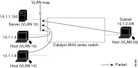
This procedure configures ACLs with VLAN maps to deny access to a server on another VLAN. The VLAN map SERVER 1_ACL denies access to hosts in subnet 10.1.2.0/8, host 10.1.1.4, and host 10.1.1.8. Then it permits all other IP traffic. In Step 3, VLAN map SERVER1 is applied to VLAN 10.
To configure this scenario, you could take the following steps:
Step 1 ![]() Define the IP ACL to match and permit the correct packets.
Define the IP ACL to match and permit the correct packets.
Switch(config)# ip access-list extended SERVER1_ACL
Switch(config-ext-nacl))# permit ip 10.1.2.0 0.0.0.255 host 10.1.1.100
Switch(config-ext-nacl))# permit ip host 10.1.1.4 host 10.1.1.100
Switch(config-ext-nacl))# permit ip host 10.1.1.8 host 10.1.1.100
Switch(config-ext-nacl))# exit
Step 2 ![]() Define a VLAN map using the ACL to drop IP packets that match SERVER1_ACL and forward IP packets that do not match the ACL.
Define a VLAN map using the ACL to drop IP packets that match SERVER1_ACL and forward IP packets that do not match the ACL.
Switch(config)# vlan access-map SERVER1_MAP
Switch(config-access-map)# match ip address SERVER1_ACL
Switch(config-access-map)# action drop
Switch(config)# vlan access-map SERVER1_MAP 20
Switch(config-access-map)# action forward
Switch(config-access-map)# exit
Step 3 ![]() Apply the VLAN map to VLAN 10.
Apply the VLAN map to VLAN 10.
Switch(config)# vlan filter SERVER1_MAP vlan-list 10.
Displaying VLAN Access Map Information
To display information about VLAN access maps or VLAN filters, perform one of these tasks.
This is a sample output of the show vlan access-map command:
Switch# show vlan access-map
Vlan access-map "map_1" 10
Match clauses:
ip address: ip1
Action:
drop
Vlan access-map "map_1" 20
Match clauses:
mac address: mac1
Action:
forward
Vlan access-map "map_1" 30
Match clauses:
Action:
drop
Note ![]() Sequence 30 does not have a match clause. All packets (IP as well as non-IP) will be matched against it and dropped.
Sequence 30 does not have a match clause. All packets (IP as well as non-IP) will be matched against it and dropped.
This is a sample output of the show vlan filter command:
Switch# show vlan filter
VLAN Map map_1 is filtering VLANs:
20-22
Using VLAN Maps with Router ACLs
If the VLAN map has a match clause for a packet type (IP or MAC) and the packet does not match the type, the default is to drop the packet. If there is no match clause in the VLAN map, and no action is specified, the packet is forwarded if it does not match any VLAN map entry.
Note ![]() You cannot combine VLAN maps or input router ACLs with port ACLs on a switch.
You cannot combine VLAN maps or input router ACLs with port ACLs on a switch.
Guidelines for Using Router ACLs and VLAN Maps
Use these guidelines when you need to use a router ACL and a VLAN map on the same VLAN.
Because the switch hardware performs one lookup for each direction (input and output), you must merge a router ACL and a VLAN map when they are configured on the same VLAN. Merging the router ACL with the VLAN map can significantly increase the number of ACEs.
When possible, try to write the ACL so that all entries have a single action except for the final, default action. You should write the ACL using one of these two forms:
permit...
permit...
permit...
deny ip any any
or
deny...
deny...
deny...
permit ip any any
To define multiple permit or deny actions in an ACL, group each action type together to reduce the number of entries.
If you need to specify the full-flow mode and the ACL contains both IP ACEs and TCP/UDP/ICMP ACEs with Layer 4 information, put the Layer 4 ACEs at the end of the list. Doing this gives priority to the filtering of traffic based on IP addresses.
Examples of Router ACLs and VLAN Maps Applied to VLANs
These examples show how router ACLs and VLAN maps are applied on a VLAN to control the access of switched, bridged, routed, and multicast packets. Although the following illustrations show packets being forwarded to their destination, each time a packet crosses a line indicating a VLAN map or an ACL, the packet could be dropped rather than forwarded.
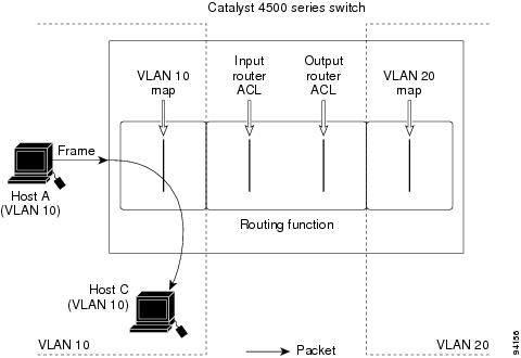
ACLs and Switched Packets
Figure 35-5 shows how an ACL processes packets that are switched within a VLAN. Packets switched within the VLAN are not processed by router ACLs.
Figure 35-5 Applying ACLs on Switched Packets
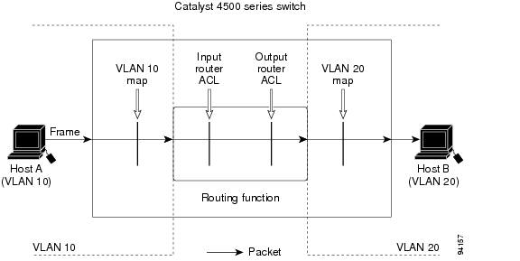
ACLs and Routed Packets
Figure 35-6 shows how ACLs are applied on routed packets. For routed packets, the ACLs are applied in this order:
1. ![]() VLAN map for input VLAN
VLAN map for input VLAN
2. ![]() Input router ACL
Input router ACL
3. ![]() Output router ACL
Output router ACL
4. ![]() VLAN map for output VLAN
VLAN map for output VLAN
Figure 35-6 Applying ACLs on Routed Packets
Configuring PACLs
This section describes how to configure PACLs, which are used to control filtering on Layer 2 interfaces. PACLs can filter traffic to or from Layer 2 interfaces based on Layer 3 information, Layer 4 head information or non-IP Layer 2 information.
This section contains the following topics:
•![]() PACL Configuration Guidelines
PACL Configuration Guidelines
•![]() Configuring IP and MAC ACLs on a Layer 2 Interface
Configuring IP and MAC ACLs on a Layer 2 Interface
•![]() Using PACL with Access-Group Mode
Using PACL with Access-Group Mode
•![]() Configuring Access-group Mode on Layer 2 Interface
Configuring Access-group Mode on Layer 2 Interface
•![]() Applying ACLs to a Layer 2 Interface
Applying ACLs to a Layer 2 Interface
•![]() Displaying an ACL Configuration on a Layer 2 Interface
Displaying an ACL Configuration on a Layer 2 Interface
Creating a PACL
To create a PACL and apply it to one or more interfaces, perform this task:
Step 1 ![]() Create the standard or extended IP ACLs or named MAC extended ACLs that you want to apply to the interface.
Create the standard or extended IP ACLs or named MAC extended ACLs that you want to apply to the interface.
Step 2 ![]() Use the ip access-group or mac access-group interface command to apply a IP ACL or MAC ACL to one or more Layer 2 interfaces.
Use the ip access-group or mac access-group interface command to apply a IP ACL or MAC ACL to one or more Layer 2 interfaces.
PACL Configuration Guidelines
Consider the following guidelines when configuring PACLs:
•![]() There can be at most one IP access list and MAC access list applied to the same Layer 2 interface per direction.
There can be at most one IP access list and MAC access list applied to the same Layer 2 interface per direction.
•![]() The IP access list filters only IP packets, whereas the MAC access list filters only non-IP packets.
The IP access list filters only IP packets, whereas the MAC access list filters only non-IP packets.
•![]() The number of ACLs and ACEs that can be configured as part of a PACL are bounded by the hardware resources on the switch. Those hardware resources are shared by various ACL features
The number of ACLs and ACEs that can be configured as part of a PACL are bounded by the hardware resources on the switch. Those hardware resources are shared by various ACL features
(for example, RACL, VACL) that are configured on the system. If there are insufficient hardware resources to program PACL in hardware, the actions for input and output PACLs differ:
–![]() For input PACLs, some packets are sent to CPU for software forwarding.
For input PACLs, some packets are sent to CPU for software forwarding.
–![]() For output PACLs, the PACL is disabled on the port.
For output PACLs, the PACL is disabled on the port.
•![]() These restrictions pertain to output PACLs only:
These restrictions pertain to output PACLs only:
–![]() If there are insufficient hardware resources to program the PACL, the output PACL is not applied to the port, and you receive a warning message.
If there are insufficient hardware resources to program the PACL, the output PACL is not applied to the port, and you receive a warning message.
–![]() If an output PACL is configured on a Layer 2 port, then neither a VACL nor a Router ACL can be configured on the VLANs to which the Layer 2 port belongs.
If an output PACL is configured on a Layer 2 port, then neither a VACL nor a Router ACL can be configured on the VLANs to which the Layer 2 port belongs.
If any VACL or Router ACL is configured on the VLANs to which the Layer 2 port belongs, the output PACL cannot be configured on the Layer 2 port. That is, PACLs and VLAN-based ACLs (VACL and Router ACL) are mutually exclusive on Layer 2 ports.
•![]() The input IP ACL logging option is supported, although logging is not supported for output IP ACLs, and MAC ACLs.
The input IP ACL logging option is supported, although logging is not supported for output IP ACLs, and MAC ACLs.
•![]() The access group mode can change the way PACLs interact with other ACLs. To maintain consistent behavior across Cisco platforms, use the default access group mode.
The access group mode can change the way PACLs interact with other ACLs. To maintain consistent behavior across Cisco platforms, use the default access group mode.
Configuring IP and MAC ACLs on a Layer 2 Interface
Only IP or MAC ACLs can be applied to Layer 2 physical interfaces. Standard (numbered, named) and Extended (numbered, named) IP ACLs, and Extended Named MAC ACLs are also supported.
To apply IP or MAC ACLs on a Layer 2 interface, perform this task:
The following example shows how to configure the Extended Named IP ACL simple-ip-acl to permit all TCP traffic and implicitly deny all other IP traffic:
Switch(config)# ip access-list extended simple-ip-acl
Switch(config-ext-nacl)# permit tcp any any
Switch(config-ext-nacl)# end
The following example shows how to configure the Extended Named MACL simple-mac-acl to permit source host 000.000.011 to any destination host:
Switch(config)# mac access-list extended simple-mac-acl
Switch(config-ext-macl)# permit host 000.000.011 any
Switch(config-ext-macl)# end
Using PACL with Access-Group Mode
You can use the access group mode to change the way PACLs interact with other ACLs. For example, if a Layer 2 interface belongs to VLAN100, VACL (VLAN filter) V1 is applied on VLAN100, and PACL P1 is applied on the Layer 2 interface. In this situation, you must specify how P1 and V1 impact the traffic with the Layer 2 interface on VLAN100. In a per-interface fashion, the access-group mode command can be used to specify one of the desired behaviors that are defined below.
The following modes are defined:
•![]() prefer port mode—If PACL is configured on a Layer 2 interface, then PACL takes effect and overwrites the effect of other ACLs (Router ACL and VACL). If no PACL feature is configured on the Layer 2 interface, other features applicable to the interface are merged and applied on the interface. This is the default access group mode.
prefer port mode—If PACL is configured on a Layer 2 interface, then PACL takes effect and overwrites the effect of other ACLs (Router ACL and VACL). If no PACL feature is configured on the Layer 2 interface, other features applicable to the interface are merged and applied on the interface. This is the default access group mode.
•![]() prefer vlan mode—VLAN-based ACL features take effect on the port provided they have been applied on the port and no PACLs are in effect. If no VLAN-based ACL features are applicable to the Layer 2 interface, then the PACL feature already on the interface is applied.
prefer vlan mode—VLAN-based ACL features take effect on the port provided they have been applied on the port and no PACLs are in effect. If no VLAN-based ACL features are applicable to the Layer 2 interface, then the PACL feature already on the interface is applied.
•![]() merge mode—Merges applicable ACL features before they are programmed into the hardware.
merge mode—Merges applicable ACL features before they are programmed into the hardware.
Note ![]() Because output PACLs are mutually exclusive with VACL and Router ACLs, the access group mode does not change the behavior of output traffic filtering.
Because output PACLs are mutually exclusive with VACL and Router ACLs, the access group mode does not change the behavior of output traffic filtering.
Configuring Access-group Mode on Layer 2 Interface
To configure an access mode on a Layer 2 interface, perform this task:
This example shows how to merge and apply features other than PACL on the interface:
Switch# configure t
Switch(config)# interface
interface
Switch(config-if)# access-group mode prefer port
This example shows how to merge applicable ACL features before they are programmed into hardware:
Switch# configure t
Switch(config)# interface
interface
Switch(config-if)# access-group mode merge
Applying ACLs to a Layer 2 Interface
To apply IP and MAC ACLs to a Layer 2 interface, perform one of these tasks:
Note ![]() Supervisor Engines III and Supervisor Engine IV running on a Catalyst 4500 series switch support both input and output PACLs on an interface.
Supervisor Engines III and Supervisor Engine IV running on a Catalyst 4500 series switch support both input and output PACLs on an interface.
This example applies the extended named IP ACL simple-ip-acl to interface FastEthernet 6/1 ingress traffic:
Switch# configure t
Switch(config)# interface fastEthernet 6/1
Switch(config-if)# ip access-group simple-ip-acl in
This example applies the extended named MAC ACL simple-mac-acl to interface FastEthernet 6/1 egress traffic:
Switch# configure t
Switch(config)# interface fastEthernet 6/1
Switch(config-if)# mac access-group simple-mac-acl out
Displaying an ACL Configuration on a Layer 2 Interface
To display information about an ACL configuration on Layer 2 interfaces, perform one of these tasks:
This example shows that the IP access group simple-ip-acl is configured on the inbound direction of interface fa6/1:
Switch# show ip interface fast 6/1
FastEthernet6/1 is up, line protocol is up
Inbound access list is simple-ip-acl
Outgoing access list is not set
This example shows that MAC access group simple-mac-acl is configured on the inbound direction of interface fa6/1:
Switch# show mac access-group interface fast 6/1
Interface FastEthernet6/1:
Inbound access-list is simple-mac-acl
Outbound access-list is not set
This example shows that access group merge is configured on interface fa6/1:
Switch# show access-group mode interface fast 6/1
Interface FastEthernet6/1:
Access group mode is: merge
Using PACL with VLAN Maps and Router ACLs
For output PACLs, there is no interaction with VACL or output Router ACLs. (See the restrictions listed in the "PACL Configuration Guidelines" section.) For input PACLs, however, the interaction with Router ACLs and VACLs depends on the interface access group mode as shown in Table 35-1.
Each ACL Type listed in Table 35-1 is synonymous with a different scenario, as explained in the following discussion.
Scenario 1: Host A is connected to an interface in VLAN 20, which has an SVI configured. The interface has input PACL configured, and the SVI has input Router ACL configured as shown in Figure 35-7:
Figure 35-7 Scenario 1: PACL Interaction with an Input Router ACL

If the interface access group mode is prefer port, then only the input PACL is applied on the ingress traffic from Host A. If the mode is prefer vlan, then only the input Router ACL is applied to ingress traffic from Host A that requires routing. If the mode is merge, then the input PACL is first applied to the ingress traffic from Host A, and the input Router ACL is applied on the traffic that requires routing.
Scenario 2: Host A is connected to an interface in VLAN 10, which has a VACL (VLAN Map) configured and an input PACL configured as shown in Figure 35-8:
Figure 35-8 Scenario 2: PACL Interaction with a VACL

If the interface access group mode is prefer port, then only the input PACL is applied on the ingress traffic from Host A. If the mode is prefer vlan, then only the VACL is applied to the ingress traffic from Host A. If the mode is merge, the input PACL is first applied to the ingress traffic from Host A, and the VACL is applied on the traffic.
Scenario 3: Host A is connected to an interface in VLAN 10, which has a VACL and an SVI configured. The SVI has an input Router ACL configured and the interface has an input PACL configured, as shown in Figure 35-9:
Figure 35-9 Scenario 3: VACL and Input Router ACL

If the interface access group mode is prefer port, then only the input PACL is applied on the ingress traffic from Host A. If the mode is prefer vlan, then the merged results of the VACL and the input Router ACL are applied to the ingress traffic from Host A. If the mode is merge, the input PACL is first applied to the ingress traffic from Host A, the VACL is applied on the traffic and finally, and the input Router ACL is applied to the traffic that needs routing. (that is, the merged results of the input PACL, VACL, and input Router ACL are applied to the traffic).
 Feedback