- Index
- Preface
- Product Overview
- Command-Line Interfaces
- Configuring the Switch for the First Time
- Configuring Interfaces
- Checking Port Status and Connectivity
- Configuring Supervisor Engine Redundancy Using RPR and SSO
- Environmental Monitoring and Power Management
- Configuring Power over Ethernet
- Configuring Switches with Web-based Tools
- Understanding and Configuring VLANs
- Configuring Layer 2 Ethernet Interfaces
- Configuring SmartPort Macros
- Understanding and Configuring STP
- Configuring STP Features
- Understanding and Configuring Multiple Spanning Trees
- Understanding and Configuring EtherChannel
- Configuring IGMP Snooping and Filtering
- Configuring 802.1Q and Layer 2 Protocol Tunneling
- Understanding and Configuring CDP
- Configuring UDLD
- Configuring Unidirectional Ethernet
- Configuring Layer 3 Interfaces
- Configuring Cisco Express Forwarding
- Understanding and Configuring IP Multicast
- Configuring Policy-Based Routing
- Configuring VRF-lite
- Configuring QoS
- Configuring Voice Interfaces
- Understanding and Configuring 802.1X Port-Based Authentication
- Configuring Port Security
- Configuring DHCP Snooping and IP Source Guard
- Understanding and Configuring Dynamic ARP Inspection
- Configuring Network Security with ACLs
- Configuring Private VLANs
- Port Unicast and Multicast Flood Blocking
- Configuring Port-Based Traffic Control
- Configuring SPAN and RSPAN
- Configuring NetFlow Statistics Collection
- Acronyms
- Overview of Root Guard
- Overview of Loop Guard
- Overview of PortFast
- Overview of BPDU Guard
- Overview of PortFast BPDU Filtering
- Overview of UplinkFast
- Overview of BackboneFast
- Enabling Root Guard
- Enabling Loop Guard
- Enabling PortFast
- Enabling BPDU Guard
- Enabling PortFast BPDU Filtering
- Enabling UplinkFast
- Enabling BackboneFast
Configuring STP Features
This chapter describes the Spanning Tree Protocol (STP) features supported on the Catalyst 4500 series switches. It also provides guidelines, procedures, and configuration examples.
This chapter includes the following major sections:
•![]() Overview of PortFast BPDU Filtering
Overview of PortFast BPDU Filtering
•![]() Enabling PortFast BPDU Filtering
Enabling PortFast BPDU Filtering

Note ![]() For information on configuring STP, see Chapter 13, "Understanding and Configuring STP."
For information on configuring STP, see Chapter 13, "Understanding and Configuring STP."
Note ![]() For complete syntax and usage information for the switch commands used in this chapter, look at the Cisco Catalyst 4500 Series Switch Command Reference and related publications at this location:
For complete syntax and usage information for the switch commands used in this chapter, look at the Cisco Catalyst 4500 Series Switch Command Reference and related publications at this location:
http://www.cisco.com/en/US/products/hw/switches/ps4324/index.html
If the command is not found in the Catalyst 4500 Command Reference, it is located in the larger Cisco IOS library. Refer to the Catalyst 4500 Series Switch Cisco IOS Command Reference and related publications at this location:
http://www.cisco.com/en/US/products/ps6350/index.html
Overview of Root Guard
Spanning Tree root guard forces an interface to become a designated port, to protect the current root status and prevent surrounding switches from becoming the root switch.
When you enable root guard on a per-port basis, it is automatically applied to all of the active VLANs to which that port belongs. When you disable root guard, it is disabled for the specified port and the port automatically goes into the listening state.
When a switch that has ports with root guard enabled detects a new root, the ports will go into root-inconsistent state. Then, when the switch no longer detects a new root, its ports will automatically go into the listening state.
Overview of Loop Guard
Loop guard helps prevent bridging loops that could occur because of a unidirectional link failure on a point-to-point link. When enabled globally, loop guard applies to all point-to-point ports on the system. Loop guard detects root ports and blocked ports and ensures that they keep receiving BPDUs from their designated port on the segment. If a loop-guard-enabled root or blocked port stop receiving BPDUs from its designated port, it transitions to the blocking state, assuming there is a physical link error on this port. The port recovers from this state as soon as it receives a BPDU.
You can enable loop guard on a per-port basis. When you enable loop guard, it is automatically applied to all of the active instances or VLANs to which that port belongs. When you disable loop guard, it is disabled for the specified ports. Disabling loop guard moves all loop-inconsistent ports to the listening state.
If you enable loop guard on a channel and the first link becomes unidirectional, loop guard blocks the entire channel until the affected port is removed from the channel. Figure 14-1 shows loop guard in a triangular switch configuration.
Figure 14-1 Triangular Switch Configuration with Loop Guard

Figure 14-1 illustrates the following configuration:
•![]() Switches A and B are distribution switches.
Switches A and B are distribution switches.
•![]() Switch C is an access switch.
Switch C is an access switch.
•![]() Loop guard is enabled on ports 3/1 and 3/2 on Switches A, B, and C.
Loop guard is enabled on ports 3/1 and 3/2 on Switches A, B, and C.
Enabling loop guard on a root switch has no effect but provides protection when a root switch becomes a nonroot switch.
Follow these guidelines when using loop guard:
•![]() Do not enable loop guard on PortFast-enabled or dynamic VLAN ports.
Do not enable loop guard on PortFast-enabled or dynamic VLAN ports.
•![]() Do not enable loop guard if root guard is enabled.
Do not enable loop guard if root guard is enabled.
Loop guard interacts with other features as follows:
•![]() Loop guard does not affect the functionality of UplinkFast or BackboneFast.
Loop guard does not affect the functionality of UplinkFast or BackboneFast.
•![]() Enabling loop guard on ports that are not connected to a point-to-point link will not work.
Enabling loop guard on ports that are not connected to a point-to-point link will not work.
•![]() Root guard forces a port to always be the root port. Loop guard is effective only if the port is a root port or an alternate port. You cannot enable loop guard and root guard on a port at the same time.
Root guard forces a port to always be the root port. Loop guard is effective only if the port is a root port or an alternate port. You cannot enable loop guard and root guard on a port at the same time.
•![]() Loop guard uses the ports known to spanning tree. Loop guard can take advantage of logical ports provided by the Port Aggregation Protocol (PAgP). However, to form a channel, all the physical ports grouped in the channel must have compatible configurations. PAgP enforces uniform configurations of root guard or loop guard on all the physical ports to form a channel.
Loop guard uses the ports known to spanning tree. Loop guard can take advantage of logical ports provided by the Port Aggregation Protocol (PAgP). However, to form a channel, all the physical ports grouped in the channel must have compatible configurations. PAgP enforces uniform configurations of root guard or loop guard on all the physical ports to form a channel.
These caveats apply to loop guard:
–![]() Spanning tree always chooses the first operational port in the channel to send the BPDUs. If that link becomes unidirectional, loop guard blocks the channel, even if other links in the channel are functioning properly.
Spanning tree always chooses the first operational port in the channel to send the BPDUs. If that link becomes unidirectional, loop guard blocks the channel, even if other links in the channel are functioning properly.
–![]() If a set of ports that are already blocked by loop guard are grouped together to form a channel, spanning tree loses all the state information for those ports and the new channel port may obtain the forwarding state with a designated role.
If a set of ports that are already blocked by loop guard are grouped together to form a channel, spanning tree loses all the state information for those ports and the new channel port may obtain the forwarding state with a designated role.
–![]() If a channel is blocked by loop guard and the channel breaks, spanning tree loses all the state information. The individual physical ports may obtain the forwarding state with the designated role, even if one or more of the links that formed the channel are unidirectional.
If a channel is blocked by loop guard and the channel breaks, spanning tree loses all the state information. The individual physical ports may obtain the forwarding state with the designated role, even if one or more of the links that formed the channel are unidirectional.
Note ![]() You can enable UniDirectional Link Detection (UDLD) to help isolate the link failure. A loop may occur until UDLD detects the failure, but loop guard will not be able to detect it.
You can enable UniDirectional Link Detection (UDLD) to help isolate the link failure. A loop may occur until UDLD detects the failure, but loop guard will not be able to detect it.
•![]() Loop guard has no effect on a disabled spanning tree instance or a VLAN.
Loop guard has no effect on a disabled spanning tree instance or a VLAN.
Overview of PortFast
Spanning Tree PortFast causes an interface configured as a Layer 2 access port to enter the forwarding state immediately, bypassing the listening and learning states. You can use PortFast on Layer 2 access ports connected to a single workstation or server to allow those devices to connect to the network immediately, rather than waiting for spanning tree to converge. If the interface receives a bridge protocol data unit (BPDU), which should not happen if the interface is connected to a single workstation or server, spanning tree puts the port into the blocking state.
Note ![]() Because the purpose of PortFast is to minimize the time that access ports must wait for spanning tree to converge, it is most effective when used on access ports. If you enable PortFast on a port connecting to another switch, you risk creating a spanning tree loop.
Because the purpose of PortFast is to minimize the time that access ports must wait for spanning tree to converge, it is most effective when used on access ports. If you enable PortFast on a port connecting to another switch, you risk creating a spanning tree loop.
Overview of BPDU Guard
Spanning Tree BPDU guard shuts down PortFast-configured interfaces that receive BPDUs, rather than putting them into the spanning tree blocking state. In a valid configuration, PortFast-configured interfaces do not receive BPDUs. Reception of a BPDU by a PortFast-configured interface signals an invalid configuration, such as connection of an unauthorized device. BPDU guard provides a secure response to invalid configurations, because the administrator must manually put the interface back in service.
Note ![]() When the BPDU guard feature is enabled, spanning tree applies the BPDU guard feature to all PortFast-configured interfaces.
When the BPDU guard feature is enabled, spanning tree applies the BPDU guard feature to all PortFast-configured interfaces.
Overview of PortFast BPDU Filtering
Cisco IOS Release 12.2(25)EW and later support PortFast BPDU filtering, which allows the administrator to prevent the system from sending or even receiving BPDUs on specified ports.
When configured globally, PortFast BPDU filtering applies to all operational PortFast ports. Ports in an operational PortFast state are supposed to be connected to hosts that typically drop BPDUs. If an operational PortFast port receives a BPDU, it immediately loses its operational PortFast status. In that case, PortFast BPDU filtering is disabled on this port and STP resumes sending BPDUs on this port.
PortFast BPDU filtering can also be configured on a per-port basis. When PortFast BPDU filtering is explicitly configured on a port, it does not send any BPDUs and drops all BPDUs it receives.

When you enable PortFast BPDU filtering globally and set the port configuration as the default for PortFast BPDU filtering (see the "Enabling PortFast BPDU Filtering" section), PortFast enables or disables PortFast BPDU filtering.
If the port configuration is not set to default, then the PortFast configuration will not affect PortFast BPDU filtering. Table 14-1 lists all the possible PortFast BPDU filtering combinations. PortFast BPDU filtering allows access ports to move directly to the forwarding state as soon as the end hosts are connected.
|
|
|
|
|
|---|---|---|---|
Default |
Enable |
Enable |
Enable1 |
Default |
Enable |
Disable |
Disable |
Default |
Disable |
Not applicable |
Disable |
Disable |
Not applicable |
Not applicable |
Disable |
Enable |
Not applicable |
Not applicable |
Enable |
1 The port transmits at least 10 BPDUs. If this port receives any BPDUs, then PortFast and PortFast BPDU filtering are disabled. |
Overview of UplinkFast
Note ![]() UplinkFast is most useful in wiring-closet switches. This feature might not be useful for other types of applications.
UplinkFast is most useful in wiring-closet switches. This feature might not be useful for other types of applications.
Spanning Tree UplinkFast provides fast convergence after a direct link failure and uses uplink groups to achieve load balancing between redundant Layer 2 links. Convergence is the speed and ability of a group of internetworking devices running a specific routing protocol to agree on the topology of an internetwork after a change in that topology. An uplink group is a set of Layer 2 interfaces (per VLAN), only one of which is forwarding at any given time. Specifically, an uplink group consists of the root port (which is forwarding) and a set of blocked ports, except for self-looping ports. The uplink group provides an alternate path in case the currently forwarding link fails.
Figure 14-2 shows an example of a topology with no link failures. Switch A, the root switch, is connected directly to Switch B over link L1 and to Switch C over link L2. The Layer 2 interface on Switch C that is connected directly to Switch B is in the blocking state.
Figure 14-2 UplinkFast Before Direct Link Failure

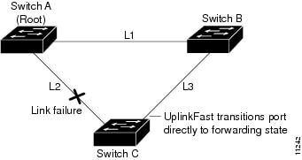
If Switch C detects a link failure on the currently active link L2 on the root port (a direct link failure), UplinkFast unblocks the blocked port on Switch C and transitions it to the forwarding state without going through the listening and learning states, as shown in Figure 14-3. This switchover takes approximately one to five seconds.
Figure 14-3 UplinkFast After Direct Link Failure
Overview of BackboneFast
BackboneFast is a complementary technology to UplinkFast. Whereas UplinkFast is designed to quickly respond to failures on links directly connected to leaf-node switches, it does not help with indirect failures in the backbone core. BackboneFast optimizes based on the Max Age setting. It allows the default convergence time for indirect failures to be reduced from 50 seconds to 30 seconds. However, it never eliminates forward delays and offers no assistance for direct failures.
Note ![]() BackboneFast should be enabled on every switch in your network.
BackboneFast should be enabled on every switch in your network.
Sometimes a switch receives a BPDU from a designated switch that identifies the root bridge and the designated bridge as the same switch. Because this shouldn't happen, the BPDU is considered inferior.
BPDUs are considered inferior when a link from the designated switch has lost its link to the root bridge. The designated switch transmits the BPDUs with the information that it is now the root bridge as well as the designated bridge. The receiving switch will ignore the inferior BPDU for the time defined by the Max Age setting.
After receiving inferior BPDUs, the receiving switch will try to determine if there is an alternate path to the root bridge.
•![]() If the port that the inferior BPDUs are received on is already in blocking mode, then the root port and other blocked ports on the switch become alternate paths to the root bridge.
If the port that the inferior BPDUs are received on is already in blocking mode, then the root port and other blocked ports on the switch become alternate paths to the root bridge.
•![]() If the inferior BPDUs are received on a root port, then all presently blocking ports become the alternate paths to the root bridge. Also, if the inferior BPDUs are received on a root port and there are no other blocking ports on the switch, the receiving switch assumes that the link to the root bridge is down and the time defined by the Max Age setting expires, which turns the switch into the root switch.
If the inferior BPDUs are received on a root port, then all presently blocking ports become the alternate paths to the root bridge. Also, if the inferior BPDUs are received on a root port and there are no other blocking ports on the switch, the receiving switch assumes that the link to the root bridge is down and the time defined by the Max Age setting expires, which turns the switch into the root switch.
If the switch finds an alternate path to the root bridge, it will use this new alternate path. This new path, and any other alternate paths, will be used to send a Root Link Query (RLQ) BPDU. When BackboneFast is enabled, the RLQ BPDUs are sent out as soon as an inferior BPDU is received. This process can enable faster convergence in the event of a backbone link failure.
Figure 14-4 shows an example of a topology with no link failures. Switch A, the root switch, connects directly to Switch B over link L1 and to Switch C over link L2. In this example, because switch B has a lower priority than A but higher than C, switch B becomes the designated bridge for L3. Consequently, the Layer 2 interface on Switch C that connects directly to Switch B must be in the blocking state.
Figure 14-4 BackboneFast Before Indirect Link Failure
Next, assume that L1 fails. Switch A and Switch B, the switches directly connected to this segment, instantly know that the link is down. The blocking interface on Switch C must enter the forwarding state for the network to recover by itself. However, because L1 is not directly connected to Switch C, Switch C does not start sending any BPDUs on L3 under the normal rules of STP until the time defined by the Max Age setting has expired.
In an STP environment without BackboneFast, if L1 should fail, Switch C cannot detect this failure because it is not connected directly to link L1. However, because Switch B is directly connected to the root switch over L1, Switch B detects the failure and elects itself the root. Then Switch B begins sending configuration BDPUs to Switch C, listing itself as the root.
Here is what happens additionally when you use BackboneFast to eliminate the time defined by the Max Age setting (20-second) delay:
1. ![]() When Switch C receives the inferior configuration BPDUs from Switch B, Switch C infers that an indirect failure has occurred.
When Switch C receives the inferior configuration BPDUs from Switch B, Switch C infers that an indirect failure has occurred.
2. ![]() Switch C then sends out an RLQ.
Switch C then sends out an RLQ.
3. ![]() Switch A receives the RLQ. Because Switch A is the root bridge, it replies with an RLQ response, listing itself as the root bridge.
Switch A receives the RLQ. Because Switch A is the root bridge, it replies with an RLQ response, listing itself as the root bridge.
4. ![]() When Switch C receives the RLQ response on its existing root port, it knows that it still has a stable connection to the root bridge. Because Switch C originated the RLQ request, it does not need to forward the RLQ response on to other switches.
When Switch C receives the RLQ response on its existing root port, it knows that it still has a stable connection to the root bridge. Because Switch C originated the RLQ request, it does not need to forward the RLQ response on to other switches.
5. ![]() BackboneFast allows the blocked port on Switch C to move immediately to the listening state without waiting for the time defined by the Max Age setting for the port to expire.
BackboneFast allows the blocked port on Switch C to move immediately to the listening state without waiting for the time defined by the Max Age setting for the port to expire.
6. ![]() BackboneFast transitions the Layer 2 interface on Switch C to the forwarding state, providing a path from Switch B to Switch A.
BackboneFast transitions the Layer 2 interface on Switch C to the forwarding state, providing a path from Switch B to Switch A.
This switchover takes approximately 30 seconds, twice the Forward Delay time if the default forward delay time of 15 seconds is set.
Figure 14-5 shows how BackboneFast reconfigures the topology to account for the failure of link L1.
Figure 14-5 BackboneFast after Indirect Link Failure

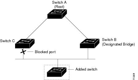
If a new switch is introduced into a shared-medium topology as shown in Figure 14-6, BackboneFast is not activated, because the inferior BPDUs did not come from the recognized designated bridge (Switch B). The new switch begins sending inferior BPDUs that say it is the root switch. However, the other switches ignore these inferior BPDUs, and the new switch learns that Switch B is the designated bridge to Switch A, the root switch.
Figure 14-6 Adding a Switch in a Shared-Medium Topology
Enabling Root Guard
To enable root guard on a Layer 2 access port (to force it to become a designated port), perform this task:
This example shows how to enable root guard on Fast Ethernet interface 5/8:
Switch(config)# interface fastethernet 5/8
Switch(config-if)# spanning-tree guard root
Switch(config-if)# end
Switch#
This example shows how to verify the configuration:
Switch# show running-config interface fastethernet 5/8
Building configuration...
Current configuration: 67 bytes
!
interface FastEthernet5/8
switchport mode access
spanning-tree guard root
end
Switch#
This example shows how to determine whether any ports are in root inconsistent state:
Switch# show spanning-tree inconsistentports
Name Interface Inconsistency
-------------------- ---------------------- ------------------
VLAN0001 FastEthernet3/1 Port Type Inconsistent
VLAN0001 FastEthernet3/2 Port Type Inconsistent
VLAN1002 FastEthernet3/1 Port Type Inconsistent
VLAN1002 FastEthernet3/2 Port Type Inconsistent
VLAN1003 FastEthernet3/1 Port Type Inconsistent
VLAN1003 FastEthernet3/2 Port Type Inconsistent
VLAN1004 FastEthernet3/1 Port Type Inconsistent
VLAN1004 FastEthernet3/2 Port Type Inconsistent
VLAN1005 FastEthernet3/1 Port Type Inconsistent
VLAN1005 FastEthernet3/2 Port Type Inconsistent
Number of inconsistent ports (segments) in the system :10
Enabling Loop Guard
You can enable loop guard globally or per port.
To enable loop guard globally on the switch, perform this task:
This example shows how to enable loop guard globally:
Switch(config)# spanning-tree loopguard default
Switch(config)# Ctrl-Z
This example shows how to verify the previous configuration of port 4/4:
Switch# show spanning-tree interface fastethernet 4/4 detail
Port 196 (FastEthernet4/4) of VLAN0010 is forwarding
Port path cost 1000, Port priority 160, Port Identifier 160.196.
Designated root has priority 32768, address 00d0.00b8.140a
Designated bridge has priority 32768, address 00d0.00b8.140a
Designated port id is 160.196, designated path cost 0
Timers:message age 0, forward delay 0, hold 0
Number of transitions to forwarding state:1
The port is in the portfast mode by portfast trunk configuration
Link type is point-to-point by default
Bpdu filter is enabled
Loop guard is enabled by default on the port
BPDU:sent 0, received 0
To enable loop guard on an interface, perform this task:
This example shows how to enable loop guard on port 4/4:
Switch(config)# interface fastEthernet 4/4
Switch(config-if)# spanning-tree guard loop
Switch(config-if)# ^Z
This example shows how to verify the configuration impact on port 4/4:
Switch# show spanning-tree interface fastEthernet 4/4 detail
Port 196 (FastEthernet4/4) of VLAN0010 is forwarding
Port path cost 1000, Port priority 160, Port Identifier 160.196.
Designated root has priority 32768, address 00d0.00b8.140a
Designated bridge has priority 32768, address 00d0.00b8.140a
Designated port id is 160.196, designated path cost 0
Timers:message age 0, forward delay 0, hold 0
Number of transitions to forwarding state:1
The port is in the portfast mode by portfast trunk configuration
Link type is point-to-point by default
Bpdu filter is enabled
Loop guard is enabled on the port
BPDU:sent 0, received 0
Switch#
Enabling PortFast
To enable PortFast on a Layer 2 access port to force it to enter the forwarding state immediately, perform this task:
This example shows how to enable PortFast on Fast Ethernet interface 5/8:
Switch(config)# interface fastethernet 5/8
Switch(config-if)# spanning-tree portfast
Switch(config-if)# end
Switch#
This example shows how to verify the configuration:
Switch# show running-config interface fastethernet 5/8
Building configuration...
Current configuration:
!
interface FastEthernet5/8
no ip address
switchport
switchport access vlan 200
switchport mode access
spanning-tree portfast
end
Switch#
Enabling BPDU Guard
To enable BPDU guard to shut down PortFast-configured interfaces that receive BPDUs, perform this task:
This example shows how to enable BPDU guard:
Switch(config)# spanning-tree portfast bpduguard
Switch(config)# end
Switch#
This example shows how to verify the BPDU configuration:
Switch# show spanning-tree summary totals
Root bridge for: none.
PortFast BPDU Guard is enabled
Etherchannel misconfiguration guard is enabled
UplinkFast is disabled
BackboneFast is disabled
Default pathcost method used is short
Name Blocking Listening Learning Forwarding STP Active
-------------------- -------- --------- -------- ---------- ----------
34 VLANs 0 0 0 36 36
Switch#
Enabling PortFast BPDU Filtering
To enable PortFast BPDU filtering globally, perform this task:
This example shows how to enable PortFast BPDU filtering on a port:
Switch(config)# spanning-tree portfast bpdufilter default
Switch(config)# Ctrl-Z
This example shows how to verify the BPDU configuration in PVST+ mode:
Switch# show spanning-tree summary totals
Root bridge for:VLAN0010
EtherChannel misconfiguration guard is enabled
Extended system ID is disabled
Portfast is enabled by default
PortFast BPDU Guard is disabled by default
Portfast BPDU Filter is enabled by default
Loopguard is disabled by default
UplinkFast is disabled
BackboneFast is disabled
Pathcost method used is long
Name Blocking Listening Learning Forwarding STP Active
---------------------- -------- --------- -------- ---------- ----------
2 vlans 0 0 0 3 3
Switch#
Note ![]() For PVST+ information, see Chapter 15, "Understanding and Configuring Multiple Spanning Trees."
For PVST+ information, see Chapter 15, "Understanding and Configuring Multiple Spanning Trees."
To enable PortFast BPDU filtering, perform this task:
This example shows how to enable PortFast BPDU filtering on port 4/4:
Switch(config)# interface fastethernet 4/4
Switch(config-if)# spanning-tree bpdufilter enable
Switch(config-if)# ^Z
This example shows how to verify that PortFast BPDU filtering is enabled:
Switch# show spanning-tree interface fastethernet 4/4
Vlan Role Sts Cost Prio.Nbr Status
---------------- ---- --- --------- -------- --------------------------------
VLAN0010 Desg FWD 1000 160.196 Edge P2p
This example shows more detail on the port:
Switch# show spanning-tree interface fastEthernet 4/4 detail
Port 196 (FastEthernet4/4) of VLAN0010 is forwarding
Port path cost 1000, Port priority 160, Port Identifier 160.196.
Designated root has priority 32768, address 00d0.00b8.140a
Designated bridge has priority 32768, address 00d0.00b8.140a
Designated port id is 160.196, designated path cost 0
Timers:message age 0, forward delay 0, hold 0
Number of transitions to forwarding state:1
The port is in the portfast mode by portfast trunk configuration
Link type is point-to-point by default
Bpdu filter is enabled
BPDU:sent 0, received 0
Switch#
Enabling UplinkFast
UplinkFast increases the bridge priority to 49,152 and adds 3000 to the spanning tree port cost of all interfaces on the switch, making it unlikely that the switch will become the root switch. The max_update_rate value represents the number of multicast packets transmitted per second (the default is 150 packets per second [pps]).
UplinkFast cannot be enabled on VLANs that have been configured for bridge priority. To enable UplinkFast on a VLAN with bridge priority configured, restore the bridge priority on the VLAN to the default value by entering a no spanning-tree vlan vlan_ID priority command in global configuration mode.
Note ![]() When you enable UplinkFast, it affects all VLANs on the switch. You cannot configure UplinkFast on an individual VLAN.
When you enable UplinkFast, it affects all VLANs on the switch. You cannot configure UplinkFast on an individual VLAN.
To enable UplinkFast, perform this task:
This example shows how to enable UplinkFast with a maximum update rate of 400 pps:
Switch(config)# spanning-tree uplinkfast max-update-rate 400
Switch(config)# exit
Switch#
This example shows how to verify which VLANS have UplinkFast enabled:
Switch# show spanning-tree uplinkfast
UplinkFast is enabled
Station update rate set to 150 packets/sec.
UplinkFast statistics
-----------------------
Number of transitions via uplinkFast (all VLANs) :14
Number of proxy multicast addresses transmitted (all VLANs) :5308
Name Interface List
-------------------- ------------------------------------
VLAN1 Fa6/9(fwd), Gi5/7
VLAN2 Gi5/7(fwd)
VLAN3 Gi5/7(fwd)
VLAN4
VLAN5
VLAN6
VLAN7
VLAN8
VLAN10
VLAN15
VLAN1002 Gi5/7(fwd)
VLAN1003 Gi5/7(fwd)
VLAN1004 Gi5/7(fwd)
VLAN1005 Gi5/7(fwd)
Switch#
Enabling BackboneFast
Note ![]() For BackboneFast to work, you must enable it on all switches in the network. BackboneFast is supported for use with third-party switches but it is not supported on Token Ring VLANs.
For BackboneFast to work, you must enable it on all switches in the network. BackboneFast is supported for use with third-party switches but it is not supported on Token Ring VLANs.
To enable BackboneFast, perform this task:
This example shows how to enable BackboneFast:
Switch(config)# spanning-tree backbonefast
Switch(config)# end
Switch#
This example shows how to verify that BackboneFast is enabled:
Switch# show spanning-tree backbonefast
BackboneFast is enabled
BackboneFast statistics
-----------------------
Number of transition via backboneFast (all VLANs) : 0
Number of inferior BPDUs received (all VLANs) : 0
Number of RLQ request PDUs received (all VLANs) : 0
Number of RLQ response PDUs received (all VLANs) : 0
Number of RLQ request PDUs sent (all VLANs) : 0
Number of RLQ response PDUs sent (all VLANs) : 0
Switch#
This example shows how to display a summary of port states:
Switch#show spanning-tree summary
Root bridge for:VLAN0001, VLAN1002-VLAN1005
Extended system ID is disabled
Portfast is enabled by default
PortFast BPDU Guard is disabled by default
Portfast BPDU Filter is enabled by default
Loopguard is disabled by default
EtherChannel misconfiguration guard is enabled
UplinkFast is enabled
BackboneFast is enabled
Pathcost method used is short
Name Blocking Listening Learning Forwarding STP Active
---------------------- -------- --------- -------- ---------- ----------
VLAN0001 0 0 0 3 3
VLAN1002 0 0 0 2 2
VLAN1003 0 0 0 2 2
VLAN1004 0 0 0 2 2
VLAN1005 0 0 0 2 2
---------------------- -------- --------- -------- ---------- ----------
5 vlans 0 0 0 11 11
BackboneFast statistics
-----------------------
Number of transition via backboneFast (all VLANs) :0
Number of inferior BPDUs received (all VLANs) :0
Number of RLQ request PDUs received (all VLANs) :0
Number of RLQ response PDUs received (all VLANs) :0
Number of RLQ request PDUs sent (all VLANs) :0
Number of RLQ response PDUs sent (all VLANs) :0
Switch#
This example shows how to display the total lines of the spanning tree state section:
Switch#show spanning-tree summary totals
Root bridge for:VLAN0001, VLAN1002-VLAN1005
Extended system ID is disabled
Portfast is enabled by default
PortFast BPDU Guard is disabled by default
Portfast BPDU Filter is enabled by default
Loopguard is disabled by default
EtherChannel misconfiguration guard is enabled
UplinkFast is enabled
BackboneFast is enabled
Pathcost method used is short
Name Blocking Listening Learning Forwarding STP Active
---------------------- -------- --------- -------- ---------- ----------
5 vlans 0 0 0 11 11
BackboneFast statistics
-----------------------
Number of transition via backboneFast (all VLANs) :0
Number of inferior BPDUs received (all VLANs) :0
Number of RLQ request PDUs received (all VLANs) :0
Number of RLQ response PDUs received (all VLANs) :0
Number of RLQ request PDUs sent (all VLANs) :0
Number of RLQ response PDUs sent (all VLANs) :0
Switch#
 Feedback