- Index
- Preface
- Product Overview
- Command-Line Interfaces
- Configuring the Switch for the First Time
- Administering the Switch
- Configuring Interfaces
- Checking Port Status and Connectivity
- Configuring Supervisor Engine Redundancy Using RPR and SSO
- Configuring NSF with SSO Supervisor Engine Redundancy
- Configuring In Service Software Upgrade Process
- Configuring Control Plane Policing
- Environmental Monitoring and Power Management
- Configuring Power over Ethernet
- Configuring Switches with Cisco Network Assistant
- Configuring VLANs, VTP, and VMPS
- Configuring IP Unnumbered Interface
- Configuring Layer 2 Ethernet Interfaces
- Configuring SmartPort Macros
- Configuring STP and MST
- Configuring Optional STP Features
- Configuring EtherChannel
- Configuring IGMP Snooping and Filtering
- Configuring 802.1Q and Layer 2 Protocol Tunneling
- Configuring CDP
- Configuring UDLD
- Configuring Unidirectional Ethernet
- Configuring Layer 3 Interfaces
- Configuring Cisco Express Forwarding
- Configuring IP Multicast
- Configuring Policy-Based Routing
- Configuring VRF-lite
- Configuring QoS
- Configuring Voice Interfaces
- Configuring 802.1X Port-Based Authentication
- Configuring Port Security
- Configuring DHCP Snooping and IP Source Guard
- Configuring Dynamic ARP Inspection
- Configuring the AGM for the First Time
- Configuring Network Security with ACLs
- Configuring Private VLANs
- Configuring Port Unicast and Multicast Flood Blocking
- Configuring Port-Based Traffic Control
- Configuring SPAN and RSPAN
- Configuring System Message Logging
- Configuring SNMP
- Configuring NetFlow
- Configuring RMON
- Performing Diagnostics on the Catalyst 4500 Series Switch
- Configuring WCCPv2 Services
- Configuring MIB Support
- ROM Monitor
- Acronyms
Catalyst 4500 Series Switch Cisco IOS Software Configuration Guide, 12.2(31)SGA
Bias-Free Language
The documentation set for this product strives to use bias-free language. For the purposes of this documentation set, bias-free is defined as language that does not imply discrimination based on age, disability, gender, racial identity, ethnic identity, sexual orientation, socioeconomic status, and intersectionality. Exceptions may be present in the documentation due to language that is hardcoded in the user interfaces of the product software, language used based on RFP documentation, or language that is used by a referenced third-party product. Learn more about how Cisco is using Inclusive Language.
- Updated:
- February 6, 2011
Chapter: Configuring Port-Based Traffic Control
Configuring Storm Control
This chapter describes how to configure port-based traffic control on the Catalyst 4500 series switch.

Note ![]() For complete syntax and usage information for the switch commands used in this chapter, refer to the Catalyst 4500 Series Switch Cisco IOS Command Reference and related publications at this location:
For complete syntax and usage information for the switch commands used in this chapter, refer to the Catalyst 4500 Series Switch Cisco IOS Command Reference and related publications at this location:
http://www.cisco.com/univercd/cc/td/doc/product/software/ios124/124cr/index.htm.
This chapter consists of these sections:
Overview of Storm Control
This section contains the following subsections:
•![]() Hardware-based Storm Control Implementation
Hardware-based Storm Control Implementation
•![]() Software-based Storm Control Implementation
Software-based Storm Control Implementation
Storm control prevents LAN interfaces from being disrupted by a broadcast storm. A broadcast storm occurs when broadcast packets flood the subnet, creating excessive traffic and degrading network performance. Errors in the protocol-stack implementation or in the network configuration can cause a broadcast storm.
Note ![]() Storm control is supported in hardware on all ports on the WS-X4516 supervisor engine. In contrast, the supervisor engines WS-X4515, WS-X4014, and WS-X4013+ support storm control in hardware on non-blocking gigabit ports and in software on all other ports, implying that the counters for these interfaces are approximate and computed. Multicast storm control is only supported on the WS-X4516 supervisor engine.
Storm control is supported in hardware on all ports on the WS-X4516 supervisor engine. In contrast, the supervisor engines WS-X4515, WS-X4014, and WS-X4013+ support storm control in hardware on non-blocking gigabit ports and in software on all other ports, implying that the counters for these interfaces are approximate and computed. Multicast storm control is only supported on the WS-X4516 supervisor engine.
Hardware-based Storm Control Implementation
Broadcast suppression uses filtering that measures broadcast activity in a subnet over a one-second interval and compares the measurement with a predefined threshold. If the threshold is reached, further broadcast activity is suppressed for the duration of the interval. Broadcast suppression is disabled by default.
Figure 40-1 shows the broadcast traffic patterns on a LAN interface over a given interval. In this example, broadcast suppression occurs between times T1 and T2 and between T4 and T5. During those intervals, the amount of broadcast traffic exceeded the configured threshold.
Figure 40-1 Storm Control Example - Hardware-based Implementation
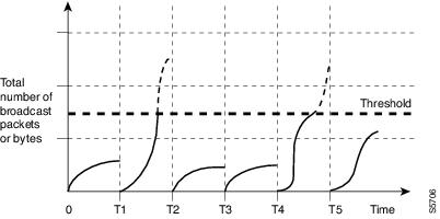
The broadcast suppression threshold numbers and the time interval combination make the broadcast suppression algorithm work with different levels of granularity. A higher threshold allows more broadcast packets to pass through.
Broadcast suppression on the Catalyst 4500 series switches is implemented in hardware. The suppression circuitry monitors packets passing from a LAN interface to the switching bus. If the packet destination address is broadcast, then the broadcast suppression circuitry tracks the current count of broadcasts within the one-second interval, and when a threshold is reached, it filters out subsequent broadcast packets.
Because hardware broadcast suppression uses a bandwidth-based method to measure broadcast activity, the most significant implementation factor is setting the percentage of total available bandwidth that can be used by broadcast traffic. Because packets do not arrive at uniform intervals, the one-second interval during which broadcast activity is measured can affect the behavior of broadcast suppression.
Software-based Storm Control Implementation
When storm control is enabled on an interface, the switch monitors packets received on the interface and determines whether or not the packets are broadcast. The switch monitors the number of broadcast packets received within a one-second time interval. When the interface threshold is met, all incoming data traffic on the interface is dropped. This threshold is specified as a percentage of total available bandwidth that can be used by broadcast traffic. If the lower threshold is specified, all data traffic is forwarded as soon as the incoming traffic falls below that threshold.
Enabling Storm Control
Note ![]() You cannot configure Storm Control on some of the members of an EtherChannel; Storm Control must be configured on all or none of the ports. If you configure Storm Control on only some of the ports, those ports will be dropped from the EtherChannel interface (put in suspended state). Therefore, you should configure Storm Control at the EtherChannel Interface level, and not at the physical interface level.
You cannot configure Storm Control on some of the members of an EtherChannel; Storm Control must be configured on all or none of the ports. If you configure Storm Control on only some of the ports, those ports will be dropped from the EtherChannel interface (put in suspended state). Therefore, you should configure Storm Control at the EtherChannel Interface level, and not at the physical interface level.
To enable storm control, perform this task:
The following example shows how to enable storm control on interface.
Switch# configure terminal
Enter configuration commands, one per line. End with CNTL/Z.
Switch(config)# interface fa3/1
Switch(config-if)# storm-control broadcast level 50
Switch(config-if)# end
Switch# write memory
Building configuration...
00:11:06: %SYS-5-CONFIG_I: Configured from console by consoleCompressed configuration from
5394 bytes to 1623 bytes[OK]
Switch#sh stor
Switch#sh storm-control
Interface Filter State Upper Lower Current
--------- ------------- ------- ------- -------
Fa3/1 Forwarding 50.00% 50.00% 0.00%
Switch#
Disabling Storm Control
To disable storm control, perform this task:
The following example shows how to disable storm control on interface.
Switch# configure terminal
Enter configuration commands, one per line. End with CNTL/Z.
Switch(config)#int fa3/1
Switch(config-if)# no storm-control
broadcast level
Switch(config-if)# end
Switch# wr
Building configuration...
00:12:09: %SYS-5-CONFIG_I: Configured from console by consoleCompressed configuration from
5357 bytes to 1594 bytes[OK]
Switch# show sto
Switch# show storm-control
Interface Filter State Upper Lower Current
--------- ------------- ------- ------- -------
Switch#
Displaying Storm Control
Note ![]() Use the show interface capabilities command to determine the mode in which storm control is supported on an interface.
Use the show interface capabilities command to determine the mode in which storm control is supported on an interface.
The following example shows an interface that supports broadcast suppression in software (sw).
Switch# show interfaces g4/4 capabilities
show interfaces g4/4 capabilities
GigabitEthernet4/4
Model: WS-X4418-Gbic
Type: 1000BaseSX
Speed: 1000
Duplex: full
Trunk encap. type: 802.1Q
Trunk mode: on,off,desirable,nonegotiate
Channel: yes
Broadcast suppression: percentage(0-100), sw
Flowcontrol: rx-(off,on,desired),tx-(off,on,desired)
VLAN Membership: static, dynamic
Fast Start: yes
Queuing: rx-(N/A), tx-(4q1t, Shaping)
CoS rewrite: yes
ToS rewrite: yes
Inline power: no
SPAN: source/destination
UDLD: yes
Link Debounce: no
Link Debounce Time: no
Port Security: yes
Dot1x: yes
Maximum MTU: 1552 bytes (Baby Giants)
Media Type: no
Switch#
The following example shows an interface that supports broadcast suppression in hardware (hw).
Switch# show interfaces g4/1 capabilities
show interfaces g4/1 capabilities
GigabitEthernet4/1
Model: WS-X4418-Gbic
Type: No Gbic
Speed: 1000
Duplex: full
Trunk encap. type: 802.1Q,ISL
Trunk mode: on,off,desirable,nonegotiate
Channel: yes
Broadcast suppression: percentage(0-100), hw
Flowcontrol: rx-(off,on,desired),tx-(off,on,desired)
VLAN Membership: static, dynamic
Fast Start: yes
Queuing: rx-(N/A), tx-(4q1t, Sharing/Shaping)
CoS rewrite: yes
ToS rewrite: yes
Inline power: no
SPAN: source/destination
UDLD: yes
Link Debounce: no
Link Debounce Time: no
Port Security: yes
Dot1x: yes
Maximum MTU: 1552 bytes (Baby Giants)
Media Type: no
Switch#
Note ![]() Use the show interfaces counters storm-control command to display a count of discarded packets.
Use the show interfaces counters storm-control command to display a count of discarded packets.
Switch# show interfaces counters storm-control
Port BcastSuppLevel TotalSuppressedPackets
Gi4/4 2.00% 0
Switch#
Note ![]() Use the show storm-control command to display the configured thresholds and status of storm on an interface.
Use the show storm-control command to display the configured thresholds and status of storm on an interface.
Switch# show storm-control
Interface Filter State Upper Lower Current
--------- ------------- ------- ------- -------
Gi4/4 Forwarding 2.00% 2.00% N/A
Switch
Note ![]() In the example shown above, "current" represents the percentage of traffic suppressed at a given instant, and the value is N/A for ports that perform suppression in hardware.
In the example shown above, "current" represents the percentage of traffic suppressed at a given instant, and the value is N/A for ports that perform suppression in hardware.
Multicast Storm Control
When a large amount of broadcast (and/or multicast) packets congest a network, the event is referred to as a broadcast storm. A LAN broadcast storm affects network performance and could paralyze the whole network.
Note ![]() Multicast storm control is available only on WS-X4516 supervisors; only a hardware-based solution is provided.
Multicast storm control is available only on WS-X4516 supervisors; only a hardware-based solution is provided.
Multicast Suppression on the WS-X4516 Supervisor Engine
Multicast suppression can be enabled on a WS-X4516 supervisor engine for all ports that have storm control enabled. Multicast suppression applies to all ports that have broadcast suppression configured on them. It also applies to ports that are configured for broadcast storm-control in the future; you cannot suppress multicast traffic only. Beginning in Cisco IOS Release 12.2(18)EW, the counters displayed with the show interface counters storm-control command includes any multicast packets that were dropped.
Separate thresholds cannot be provided for broadcast and/or multicast traffic. The threshold you configure for broadcast suppression applies to both the incoming multicast traffic and broadcast traffic.
To enable multicast suppression, perform this task:
The following example shows how to enable multicast suppression on ports that have broadcast suppression already enabled:
Switch# configure terminal
Enter configuration commands, one per line. End with CNTL/Z.
Switch(config)# storm-control broadcast include multicast
Switch(config)# end
Switch#
Multicast Suppression on the WS-X4515, WS-X4014, and WS-X4013+ Supervisor Engines
Hardware does not provide support for multicast suppression on the WS-X4515, WS-X4014, and WS-X4013+ supervisor engines. One consequence of using software-based broadcast suppression on these modules is that all incoming data packets are dropped. Irrespective of your selecting to configure broadcast suppression only, multicast packets are filtered as well on stub and blocking gigabit ports. The non blocking gigabit ports that do provide broadcast suppression in hardware also do not filter multicast packets.
 Feedback