Configuring VRF-lite

Virtual Private Networks (VPNs) provide a secure way for customers to share bandwidth over an ISP backbone network. A VPN is a collection of sites sharing a common routing table. A customer site is connected to the service provider network by one or more interfaces, and the service provider associates each interface with a VPN routing table. A VPN routing table is called a VPN routing/forwarding (VRF) table.

With the VRF-lite feature, the Catalyst 4500 series switch supports multiple VPN routing/forwarding instances in customer edge devices. (VRF-lite is also termed multi-VRF CE, or multi-VRF Customer Edge Device). VRF-lite allows a service provider to support two or more VPNs with overlapping IP addresses using one interface.

This document addresses both IPv4 and IPv6 VRF-lite.

note.gif

Noteblank.gif Starting with Cisco IOS Release 12.2(52)SG, the Catalyst 4500 switch supports VRF-lite NSF support with routing protocols OSPF/EIGRP/BGP.


note.gif

Noteblank.gif The switch does not use Multiprotocol Label Switching (MPLS) to support VPNs. For information about MPLS VRF, refer to the Cisco IOS Switching Services Configuration Guide at:

http://www.cisco.com/en/US/docs/ios/mpls/configuration/guide/mp_vpn_ipv4_ipv6_ps6922_TSD_Products_Configuration_Guide_Chapter.html


This chapter includes these topics:

note.gif

Noteblank.gif For complete syntax and usage information for the switch commands used in this chapter, see the Cisco Catalyst 4500 Series Switch Command Reference and related publications at this location:

http://www.cisco.com/en/US/products/hw/switches/ps4324/index.html

If a command is not in the Catalyst 4500 Series Switch Command Reference, you can locate it in the Cisco IOS library. See the Cisco IOS Command Reference and related publications at this location:

http://www.cisco.com/en/US/products/ps6350/index.html


About VRF-lite

VRF-lite is a feature that enables a service provider to support two or more VPNs, where IP addresses can be overlapped among the VPNs. VRF-lite uses input interfaces to distinguish routes for different VPNs and forms virtual packet-forwarding tables by associating one or more Layer 3 interfaces with each VRF. Interfaces in a VRF can be either physical, such as Ethernet ports, or logical, such as VLAN SVIs, but a Layer 3 interface cannot belong to more than one VRF at any time.

note.gif

Noteblank.gif VRF-lite interfaces must be Layer 3 interfaces.


VRF-lite includes these devices:

  • Customer edge (CE) devices provide customer access to the service provider network over a data link to one or more provider edge routers. The CE device advertises the site’s local routes to the provider edge router and learns the remote VPN routes from it. A Catalyst 4500 series switch can be a CE.
  • Provider edge (PE) routers exchange routing information with CE devices by using static routing or a routing protocol such as BGP, RIPv1, or RIPv2.

The PE is only required to maintain VPN routes for those VPNs to which it is directly attached, eliminating the need for the PE to maintain all of the service provider VPN routes. Each PE router maintains a VRF for each of its directly connected sites. Multiple interfaces on a PE router can be associated with a single VRF if all of these sites participate in the same VPN. Each VPN is mapped to a specified VRF. After learning local VPN routes from CEs, a PE router exchanges VPN routing information with other PE routers by using internal BGP (iBPG).

  • Provider routers (or core routers) are any routers in the service provider network that do not attach to CE devices.

With VRF-lite, multiple customers can share one CE, and only one physical link is used between the CE and the PE. The shared CE maintains separate VRF tables for each customer and switches or routes packets for each customer based on its own routing table. VRF-lite extends limited PE functionality to a CE device, giving it the ability to maintain separate VRF tables to extend the privacy and security of a VPN to the branch office.

Figure 41-1 shows a configuration where each Catalyst 4500 series switch acts as multiple virtual CEs. Because VRF-lite is a Layer 3 feature, each interface in a VRF must be a Layer 3 interface.

Figure 41-1 Catalyst 4500 Series Switches Acting as Multiple Virtual CEs


99721.ps

Figure 41-1 illustrates the packet-forwarding process in a VRF-lite CE-enabled network.

  • When the CE receives a packet from a VPN, it looks up the routing table based on the input interface. When a route is found, the CE forwards the packet to the PE.
  • When the ingress PE receives a packet from the CE, it performs a VRF lookup. When a route is found, the router adds a corresponding MPLS label to the packet and sends it to the MPLS network.
  • When an egress PE receives a packet from the network, it strips the label and uses the label to identify the correct VPN routing table. The egress PE then performs the normal route lookup. When a route is found, it forwards the packet to the correct adjacency.
  • When a CE receives a packet from an egress PE, it uses the input interface to look up the correct VPN routing table. If a route is found, the CE forwards the packet within the VPN.

To configure VRF, create a VRF table and specify the Layer 3 interface associated with the VRF. You then configure the routing protocols in the VPN and between the CE and the PE. BGP is the preferred routing protocol used to distribute VPN routing information across the providers’ backbone. The VRF-lite network has three major components:

  • VPN route target communities—Lists all other members of a VPN community. You need to configure VPN route targets for each VPN community member.
  • Multiprotocol BGP peering of VPN community PE routers—Propagates VRF reachability information to all members of a VPN community. You need to configure BGP peering in all PE routers within a VPN community.
  • VPN forwarding—Transports all traffic between all VPN community members across a VPN service-provider network.

VRF-lite Configuration Guidelines

IPv4 and IPv6

  • A switch with VRF-lite is shared by multiple customers, and all customers have their own routing tables.
  • Because customers use different VRF tables, you can reuse the same IP addresses. Overlapped IP addresses are allowed in different VPNs.
  • VRF-lite lets multiple customers share the same physical link between the PE and the CE. Trunk ports with multiple VLANs separate packets among customers. All customers have their own VLANs.
  • VRF-lite does not support all MPLS-VRF functionality: label exchange, LDP adjacency, or labeled packets.
  • For the PE router, there is no difference between using VRF-lite or using multiple CEs. In Figure 41-1, multiple virtual Layer 3 interfaces are connected to the VRF-lite device.
  • The Catalyst 4500 series switch supports configuring VRF by using physical ports, VLAN SVIs, or a combination of both. You can connect SVIs through an access port or a trunk port.
  • A customer can use multiple VLANs as long because they do not overlap with those of other customers. A customer’s VLANs are mapped to a specific routing table ID that is used to identify the appropriate routing tables stored on the switch.
  • The Layer 3 TCAM resource is shared between all VRFs. To ensure that any one VRF has sufficient CAM space, use the maximum routes command.
  • A Catalyst 4500 series switch using VRF can support one global network and up to 64 VRFs. The total number of routes supported is limited by the size of the TCAM.
  • A single VRF can be configured for both IPv4 and IPv6.
  • PBR and VRF cannot be configured on the same interface. Similarly, WCCP, Etherchannel and MEC cannot be configured on the same interface with VRF.
  • If an incoming packet's destination address is not found in the vrf table, the packet is dropped. Also, if insufficient TCAM space exists for a VRF route, hardware switching for that VRF is disabled and the corresponding data packets are sent to software for processing.

IPv4 Specific

  • You can use most routing protocols (BGP, OSPF, EIGRP, RIP and static routing) between the CE and the PE. However, we recommend using external BGP (EBGP) for these reasons:

blank.gif BGP does not require multiple algorithms to communicate with multiple CEs.

blank.gif BGP is designed for passing routing information between systems run by different administrations.

blank.gif BGP makes simplifies passing attributes of the routes to the CE.

  • VRF-lite does not support IGRP and ISIS.
  • Beginning with Cisco IOS Release 12.2(50)SG, Multicast and VRF can be configured together on a Layer 3 interface.
  • The Catalyst 4500 series switch supports all the PIM protocols (PIM-SM, PIM-DM, PIM-SSM, PIM BiDIR).
  • The capability vrf-lite subcommand under router ospf should be used when configuring OSPF as the routing protocol between the PE and the CE.

IPv6 specific

  • VRF-aware OSPFv3, BGPv6, EIGRPv6, and IPv6 static routing are supported.
  • VRF aware ISISv6, RIPng, IPv6 Multicast Routing(MVRF), and PIMv6 are not supported.
  • VRF-aware IPv6 route applications include: ping, telnet, ssh, tftp, ftp and traceroute. (This list does not include the Mgt interface, which is handled differently even though you can configure both IPv4 or IPv6 VRF under it.)

Configuring VRF-lite for IPv4

Configuring VRFs

To configure one or more VRFs, perform this task:


Command
Purpose

Step 1

Switch# configure terminal

Enters global configuration mode.

Step 2

Switch(config)# ip routing

Enables IP routing.

Step 3

Switch(config)# ip vrf vrf-name

Names the VRF and enters VRF configuration mode.

Step 4

Switch(config-vrf)# rd route-distinguisher

Creates a VRF table by specifying a route distinguisher. Enter either an AS number and an arbitrary number (xxx:y) or an IP address and arbitrary number (A.B.C.D:y).

Step 5

Switch(config-vrf)# route-target { export | import | both } route-target-ext-community

Creates a list of import, export, or import and export route target communities for the specified VRF. Enter either an AS system number and an arbitrary number (xxx:y) or an IP address and an arbitrary number (A.B.C.D:y).

Note This command is effective only if BGP is running.

Step 6

Switch(config-vrf)# import map route-map

(Optional) Associates a route map with the VRF.

Step 7

Switch(config-vrf)# interface interface-id

Enters interface configuration mode and specify the Layer 3 interface to be associated with the VRF. The interface can be a routed port or SVI.

Step 8

Switch(config-if)# ip vrf forwarding vrf-name

Associates the VRF with the Layer 3 interface.

Step 9

Switch(config-if)# end

Returns to privileged EXEC mode.

Step 10

Switch# show ip vrf [brief | detail | interfaces] [vrf-name]

Verifies the configuration. Displays information about the configured VRFs.

Step 11

Switch# copy running-config startup-config

(Optional) Saves your entries in the configuration file.

note.gif

Noteblank.gif For complete syntax and usage information for the following commands, see the switch command reference for this release and see the Cisco IOS Switching Services Command Reference at: http://www.cisco.com/en/US/docs/ios/ipswitch/command/reference/isw_book.html


Use the no ip vrf vrf-name global configuration command to delete a VRF and to remove all interfaces from it. Use the no ip vrf forwarding interface configuration command to remove an interface from the VRF.

Configuring VRF-Aware Services

IP services can be configured on global interfaces and within the global routing instance. IP services are enhanced to run on multiple routing instances; they are VRF-aware. Any configured VRF in the system can be specified for a VRF-aware service.

VRF-aware services are implemented in platform-independent modules. VRF provides multiple routing instances in Cisco IOS. Each platform has its own limit on the number of VRFs it supports.

VRF-aware services have the following characteristics:

  • The user can ping a host in a user-specified VRF.
  • ARP entries are learned in separate VRFs. The user can display Address Resolution Protocol (ARP) entries for specific VRFs.

Configuring the User Interface for ARP

To configure VRF-aware services for ARP, perform this task:


Command
Purpose


Switch# show ip arp vrf vrf-name

Displays the ARP table (static and dynamic entries) in the specified VRF.


Switch(config)# arp vrf vrf-name ip-address mac-address ARPA

Creates a static ARP entry in the specified VRF.

Configuring Per-VRF for TACACS+ Servers

The per-VRF for TACACS+ servers feature enables you to configure per-virtual route forwarding (per-VRF) authentication, authorization, and accounting (AAA) on TACACS+ servers.

Before configuring per-VRF on a TACACS+ server, you must have configured AAA and a server group.

You can create the VRF routing table (shown in Steps 3 and 4) and configure the interface (Steps 6, 7, and 8). The actual configuration of per-VRF on a TACACS+ server is done in Steps 10 through 13.

.

Command or Action
Purpose

Step 1

Switch> enable

Enables privileged EXEC mode.

Enter your password if prompted.

Step 2

Switch# configure terminal

Enters global configuration mode.

Step 3

Switch(config)# ip vrf vrf-name

Configures a VRF table and enters VRF configuration mode.

Step 4

Switch (config-vrf)# rd route-distinguisher

Creates routing and forwarding tables for a VRF instance.

Step 5

Switch (config-vrf)# exit

Exits VRF configuration mode.

Step 6

Switch (config)# interface interface-name

Configures an interface and enters interface configuration mode.

Step 7

Switch (config-if)# ip vrf forwarding vrf-name

Configures a VRF for the interface.

Step 8

Switch (config-if)# ip address ip-address mask [ secondary ]

Sets a primary or secondary IP address for an interface.

Step 9

Switch (config-if)# exit

Exits interface configuration mode.

Step 10

aaa group server tacacs+ group-name


Switch (config)# aaa group server tacacs+ tacacs1

Groups different TACACS+ server hosts into distinct lists and distinct methods and enters server-group configuration mode.

Step 11

server-private { ip-address | name } [ nat ] [ single-connection ] [ port port-number ] [ timeout seconds ] [ key [ 0 | 7 ] string ]


Switch (config-sg-tacacs+)# server-private 10.1.1.1 port 19 key cisco

Configures the IP address of the private TACACS+ server for the group server.

Step 12

Switch (config-sg-tacacs+)# ip vrf forwarding vrf-name

Configures the VRF reference of a AAA TACACS+ server group.

Step 13

Switch (config-sg-tacacs+)# ip tacacs source-interface subinterface-name

Uses the IP address of a specified interface for all outgoing TACACS+ packets.

Step 14

Switch (config-sg-tacacs)# exit

Exits server-group configuration mode.

The following example lists all the steps to configure per-VRF TACACS+:

Switch> enable

Switch# configure terminal

Switch (config)# ip vrf cisco

Switch (config-vrf)# rd 100:1

Switch (config-vrf)# exit

Switch (config)# interface Loopback0

Switch (config-if)# ip vrf forwarding cisco

Switch (config-if)# ip address 10.0.0.2 255.0.0.0

Switch (config-if)# exit

Switch (config-sg-tacacs+)# ip vrf forwarding cisco

Switch (config-sg-tacacs+)# ip tacacs source-interface Loopback0

Switch (config-sg-tacacs)# exit

For more information about configuring per-VRF for TACACS+ server,

http://www.cisco.com/en/US/docs/ios/sec_user_services/configuration/guide/sec_vrf_tacas_svrs.pdf

Configuring Multicast VRFs

To configure multicast within a VRF table, perform this task:


Command
Purpose

Step 1

Switch# configure terminal

Enters global configuration mode.

Step 2

Switch(config)# ip routing

Enables IP routing.

Step 3

Switch(config)# ip vrf vrf-name

Names the VRF and enters VRF configuration mode.

Step 4

Switch(config-vrf)# ip multicast-routing vrf vrf-name

(Optional) Enables global multicast routing for VRF table.

Step 5

Switch(config-vrf)# rd route-distinguisher

Creates a VRF table by specifying a route distinguisher. Enter either an AS number and an arbitrary number (xxx:y) or an IP address and arbitrary number (A.B.C.D:y).

Step 6

Switch(config-vrf)# route-target { export | import | both } route-target-ext-community

Creates a list of import, export, or import and export route target communities for the specified VRF. Enter either an AS system number and an arbitrary number (xxx:y) or an IP address and an arbitrary number (A.B.C.D:y).

The route-target-ext-community value should be the same as the route-distinguisher value entered in Step 4.

Step 7

Switch(config-vrf)# import map route-map

(Optional) Associates a route map with the VRF.

Step 8

Switch(config-vrf)# interface interface-id

Enters interface configuration mode and specifies the Layer 3 interface to be associated with the VRF. The interface can be a routed port or a SVI.

Step 9

Switch(config-if)# ip vrf forwarding vrf-name

Associates the VRF with the Layer 3 interface.

Step 10

Switch(config-if)# ip address ip-address mask

Configures IP address for the Layer 3 interface.

Step 11

Switch(config-if)# ip pim [sparse-dense mode | dense-mode | sparse-mode]

Enables PIM on the VRF-associated Layer 3 interface.

Step 12

Switch(config-if)# end

Returns to privileged EXEC mode.

Step 13

Switch# show ip vrf [ brief | detail | interfaces ] [ vrf-name ]

Verifies the configuration. Display information about the configured VRFs.

Step 14

Switch# copy running-config startup-config

(Optional) Saves your entries in the configuration file.

The following example shows how to configure multicast within a VRF table:

Switch(config)# ip routing
Switch(config)# ip vrf multiVrfA
Switch(config-vrf)# ip multicast-routing vrf multiVrfA
Switch(config-vrf)# interface GigabitEthernet3/1/0
Switch(config-if)# ip vrf forwarding multiVrfA
Switch(config-if)# ip address 172.21.200.203 255.255.255.0
Switch(config-if)# ip pim sparse-mode
 

For more information about configuring a multicast within a Multi-VRF CE, see the
Cisco IOS IP Multicast Configuration Guide, Release 12.4.

Use the no ip vrf vrf-name global configuration command to delete a VRF and to remove all interfaces from it. Use the no ip vrf forwarding interface configuration command to remove an interface from the VRF.

Configuring a VPN Routing Session

Routing within the VPN can be configured with any supported routing protocol (RIP, OSPF, or BGP) or with static routing. The configuration shown here is for OSPF, but the process is the same for other protocols.

To configure OSPF in the VPN, perform this task:


Command
Purpose

Step 1

Switch# configure terminal

Enters global configuration mode.

Step 2

Switch(config)# router ospf process-id vrf vrf-name

Enables OSPF routing, specifies a VPN forwarding table, and enters router configuration mode.

Step 3

Switch(config-router)# log-adjacency-changes

(Optional) Logs changes in the adjacency state (the default state).

Step 4

Switch(config-router)# redistribute bgp autonomous-system-number subnets

Sets the switch to redistribute information from the BGP network to the OSPF network.

Step 5

Switch(config-router)# network network-number area area-id

Defines a network address and mask on which OSPF runs and the area ID for that network address.

Step 6

Switch(config-router)# end

Returns to privileged EXEC mode.

Step 7

Switch# show ip ospf process-id

Verifies the configuration of the OSPF network.

Step 8

Switch# copy running-config startup-config

(Optional) Saves your entries in the configuration file.

Use the no router ospf process-id vrf vrf-name global configuration command to disassociate the VPN forwarding table from the OSPF routing process.

The following example shows how to configure a single VRF named VRF-RED:

Switch(config)# ip vrf VRF-RED
Switch(config-vrf)# rd 1:1
Switch(config-vrf)# exit
Switch(config)# router eigrp virtual-name
Switch(config-router)# address-family ipv4 vrf VRF-RED autonomous-system 1
Switch(config-router-af)# network 10.0.0.0 0.0.0.255
Switch(config-router-af)# topology base
Switch(config-router-topology)# default-metric 10000 100 255 1 1500
Switch(config-router-topology)# exit-af-topology
Switch(config-router-af)# exit-address-family

Configuring BGP PE to CE Routing Sessions

To configure a BGP PE to CE routing session, perform this task:


Command
Purpose

Step 1

Switch# configure terminal

Enters global configuration mode.

Step 2

Switch(config)# router bgp autonomous-system-number

Configures the BGP routing process with the AS number passed to other BGP routers and enters router configuration mode.

Step 3

Switch(config-router)# network network-number mask network-mask

Specifies a network and mask to announce using BGP.

Step 4

Switch(config-router)# redistribute ospf process-id match internal

Sets the switch to redistribute OSPF internal routes.

Step 5

Switch(config-router)# network network-number area area-id

Defines a network address and mask on which OSPF runs and the area ID for that network address.

Step 6

Switch(config-router-af)# address-family ipv4 vrf vrf-name

Defines BGP parameters for PE to CE routing sessions and enters VRF address-family mode.

Step 7

Switch(config-router-af)# neighbor address remote-as as-number

Defines a BGP session between PE and CE routers.

Step 8

Switch(config-router-af)# neighbor address activate

Activates the advertisement of the IPv4 address family.

Step 9

Switch(config-router-af)# end

Returns to privileged EXEC mode.

Step 10

Switch# show ip bgp [ ipv4 ] [ neighbors ]

Verifies BGP configuration.

Step 11

Switch# copy running-config startup-config

(Optional) Saves your entries in the configuration file.

Use the no router bgp autonomous-system-number global configuration command to delete the BGP routing process. Use the command with keywords to delete routing characteristics.

VRF-lite Configuration Example

Figure 41-2 is a simplified example of the physical connections in a network similar to that in Figure 41-1. OSPF is the protocol used in VPN1, VPN2, and the global network. BGP is used in the CE to PE connections. The example commands show how to configure the CE switch S8 and include the VRF configuration for switches S20 and S11 and the PE router commands related to traffic with switch S8. Commands for configuring the other switches are not included but would be similar.

Figure 41-2 VRF-lite Configuration Example


99722.ps

Configuring Switch S8

On switch S8, enable routing and configure VRF.

Switch# configure terminal
Enter configuration commands, one per line. End with CNTL/Z.
Switch(config)# ip routing
Switch(config)# ip vrf v11
Switch(config-vrf)# rd 800:1
Switch(config-vrf)# route-target export 800:1
Switch(config-vrf)# route-target import 800:1
Switch(config-vrf)# exit
Switch(config)# ip vrf v12
Switch(config-vrf)# rd 800:2
Switch(config-vrf)# route-target export 800:2
Switch(config-vrf)# route-target import 800:2
Switch(config-vrf)# exit
 

Configure the loopback and physical interfaces on switch S8. Fast Ethernet interface 3/5 is a trunk connection to the PE. Interfaces 3/7 and 3/11 connect to VPNs:

Switch(config)# interface loopback1
Switch(config-if)# ip vrf forwarding v11
Switch(config-if)# ip address 8.8.1.8 255.255.255.0
Switch(config-if)# exit
 
Switch(config)# interface loopback2
Switch(config-if)# ip vrf forwarding v12
Switch(config-if)# ip address 8.8.2.8 255.255.255.0
Switch(config-if)# exit
 
Switch(config)# interface FastEthernet3/5
Switch(config-if)# switchport trunk encapsulation dot1q
Switch(config-if)# switchport mode trunk
Switch(config-if)# no ip address
Switch(config-if)# exit
 
Switch(config)# interface FastEthernet3/8
Switch(config-if)# switchport access vlan 208
Switch(config-if)# no ip address
Switch(config-if)# exit
 
Switch(config)# interface FastEthernet3/11
Switch(config-if)# switchport trunk encapsulation dot1q
Switch(config-if)# switchport mode trunk
Switch(config-if)# no ip address
Switch(config-if)# exit
 

Configure the VLANs used on switch S8. VLAN 10 is used by VRF 11 between the CE and the PE. VLAN 20 is used by VRF 12 between the CE and the PE. VLANs 118 and 208 are used for VRF for the VPNs that include switch S11 and switch S20, respectively:

Switch(config)# interface Vlan10
Switch(config-if)# ip vrf forwarding v11
Switch(config-if)# ip address 38.0.0.8 255.255.255.0
Switch(config-if)# exit
 
Switch(config)# interface Vlan20
Switch(config-if)# ip vrf forwarding v12
Switch(config-if)# ip address 83.0.0.8 255.255.255.0
Switch(config-if)# exit
 
Switch(config)# interface Vlan118
Switch(config-if)# ip vrf forwarding v12
Switch(config-if)# ip address 118.0.0.8 255.255.255.0
Switch(config-if)# exit
 
Switch(config)# interface Vlan208
Switch(config-if)# ip vrf forwarding v11
Switch(config-if)# ip address 208.0.0.8 255.255.255.0
Switch(config-if)# exit
 

Configure OSPF routing in VPN1 and VPN2:

Switch(config)# router ospf 1 vrf vl1
Switch(config-router)# redistribute bgp 800 subnets
Switch(config-router)# network 208.0.0.0 0.0.0.255 area 0
Switch(config-router)# exit
Switch(config)# router ospf 2 vrf vl2
Switch(config-router)# redistribute bgp 800 subnets
Switch(config-router)# network 118.0.0.0 0.0.0.255 area 0
Switch(config-router)# exit
 

Configure BGP for CE to PE routing:

Switch(config)# router bgp 800
Switch(config-router)# address-family ipv4 vrf vl2
Switch(config-router-af)# redistribute ospf 2 match internal
Switch(config-router-af)# neighbor 83.0.0.3 remote-as 100
Switch(config-router-af)# neighbor 83.0.0.3 activate
Switch(config-router-af)# network 8.8.2.0 mask 255.255.255.0
Switch(config-router-af)# exit
 
Switch(config-router)# address-family ipv4 vrf vl1
Switch(config-router-af)# redistribute ospf 1 match internal
Switch(config-router-af)# neighbor 38.0.0.3 remote-as 100
Switch(config-router-af)# neighbor 38.0.0.3 activate
Switch(config-router-af)# network 8.8.1.0 mask 255.255.255.0
Switch(config-router-af)# end

Configuring Switch S20

Configure S20 to connect to CE:

Switch# configure terminal
Enter configuration commands, one per line. End with CNTL/Z.
Switch(config)# ip routing
Switch(config)# interface Fast Ethernet 0/7
Switch(config-if)# no switchport
Switch(config-if)# ip address 208.0.0.20 255.255.255.0
Switch(config-if)# exit
 
Switch(config)# router ospf 101
Switch(config-router)# network 208.0.0.0 0.0.0.255 area 0
Switch(config-router)# end

Configuring Switch S11

Configure S11 to connect to CE:

Switch# configure terminal
Enter configuration commands, one per line. End with CNTL/Z.
Switch(config)# ip routing
Switch(config)# interface Gigabit Ethernet 0/3
Switch(config-if)# switchport trunk encapsulation dot1q
Switch(config-if)# switchport mode trunk
Switch(config-if)# no ip address
Switch(config-if)# exit
 
Switch(config)# interface Vlan118
Switch(config-if)# ip address 118.0.0.11 255.255.255.0
Switch(config-if)# exit
 
Switch(config)# router ospf 101
Switch(config-router)# network 118.0.0.0 0.0.0.255 area 0
Switch(config-router)# end

Configuring the PE Switch S3

On switch S3 (the router), these commands configure only the connections to switch S8:

Router# configure terminal
Enter configuration commands, one per line. End with CNTL/Z.
Router(config)# ip vrf v1
Router(config-vrf)# rd 100:1
Router(config-vrf)# route-target export 100:1
Router(config-vrf)# route-target import 100:1
Router(config-vrf)# exit
 
Router(config)# ip vrf v2
Router(config-vrf)# rd 100:2
Router(config-vrf)# route-target export 100:2
Router(config-vrf)# route-target import 100:2
Router(config-vrf)# exit
 
Router(config)# ip cef
Router(config)# interface Loopback1
Router(config-if)# ip vrf forwarding v1
Router(config-if)# ip address 3.3.1.3 255.255.255.0
Router(config-if)# exit
 
Router(config)# interface Loopback2
Router(config-if)# ip vrf forwarding v2
Router(config-if)# ip address 3.3.2.3 255.255.255.0
Router(config-if)# exit
 
Router(config)# interface Fast Ethernet3/0.10
Router(config-if)# encapsulation dot1q 10
Router(config-if)# ip vrf forwarding v1
Router(config-if)# ip address 38.0.0.3 255.255.255.0
Router(config-if)# exit
 
Router(config)# interface Fast Ethernet3/0.20
Router(config-if)# encapsulation dot1q 20
Router(config-if)# ip vrf forwarding v2
Router(config-if)# ip address 83.0.0.3 255.255.255.0
Router(config-if)# exit
 
Router(config)# router bgp 100
Router(config-router)# address-family ipv4 vrf v2
Router(config-router-af)# neighbor 83.0.0.8 remote-as 800
Router(config-router-af)# neighbor 83.0.0.8 activate
Router(config-router-af)# network 3.3.2.0 mask 255.255.255.0
Router(config-router-af)# exit
Router(config-router)# address-family ipv4 vrf vl
Router(config-router-af)# neighbor 83.0.0.8 remote-as 800
Router(config-router-af)# neighbor 83.0.0.8 activate
Router(config-router-af)# network 3.3.1.0 mask 255.255.255.0
Router(config-router-af)# end

Displaying VRF-lite Status

To display information about VRF-lite configuration and status, perform one of the following tasks:


Command
Purpose

Switch# show ip protocols vrf vrf-name

Displays routing protocol information associated with a VRF.

Switch# show ip route vrf vrf-name [connected] [protocol
[as-number]] [list] [mobile] [odr] [profile] [static] [summary][supernets-only]

Displays IP routing table information associated with a VRF.

Switch# show ip vrf [ brief | detail | interfaces ] [ vrf-name ]

Displays information about the defined VRF instances.

Switch# show ip mroute vrf instance-name a.b.c.d | active | bidriectional| count | dense| interface | proxy | pruned | sparse | ssm | static | summary

Displays information about the defined VRF instances.

This example shows how to display multicast route table information within a VRF instance:

Switch# show ip mroute vrf mcast2 234.34.10.18
IP Multicast Routing Table
Flags: D - Dense, S - Sparse, B - Bidir Group, s - SSM Group, C - Connected,
L - Local, P - Pruned, R - RP-bit set, F - Register flag,
T - SPT-bit set, J - Join SPT, M - MSDP created entry,
X - Proxy Join Timer Running, A - Candidate for MSDP Advertisement,
U - URD, I - Received Source Specific Host Report,
Z - Multicast Tunnel, z - MDT-data group sender,
Y - Joined MDT-data group, y - Sending to MDT-data group
V - RD & Vector, v - Vector
Outgoing interface flags: H - Hardware switched, A - Assert winner
Timers: Uptime/Expires
Interface state: Interface, Next-Hop or VCD, State/Mode
 
(*, 234.34.10.18), 13:39:21/00:02:58, RP 1.1.1.1, flags: BC
Bidir-Upstream: Vlan134, RPF nbr 172.16.34.1
Outgoing interface list:
Vlan45, Forward/Sparse-Dense, 00:00:02/00:02:57, H
Vlan134, Bidir-Upstream/Sparse-Dense, 13:35:54/00:00:00, H
note.gif

Noteblank.gif For more information about the information in the displays, refer to the Cisco IOS Switching Services Command Reference at:

http://www.cisco.com/en/US/docs/ios/ipswitch/command/reference/isw_book.html


Configuring VRF-lite for IPv6

Configuring VRF-Aware Services

IP services can be configured on global interfaces and within the global routing instance. IP services are enhanced to run on multiple routing instances; they are VRF-aware. Any configured VRF in the system can be specified for a VRF-aware service.

VRF-aware services are implemented in platform-independent modules. VRF provides multiple routing instances in Cisco IOS. Each platform has its own limit on the number of VRFs it supports.

VRF-aware services have the following characteristics:

  • The user can ping a host in a user-specified VRF.
  • ARP entries are learned in separate VRFs. The user can display Address Resolution Protocol (ARP) entries for specific VRFs.

These services are VRF-aware:

  • Ping
  • Unicast Reverse Path Forwarding (uRPF)
  • Traceroute
  • FTP and TFTP
  • Telnet and SSH
  • NTP

Configuring the User Interface for ARP

To configure VRF-aware services for ARP, perform this task:


Command
Purpose


Switch# show ip arp vrf vrf-name

Displays the ARP table (static and dynamic entries) in the specified VRF.


Switch(config)# arp vrf vrf-name ip-address mac-address ARPA

Creates a static ARP entry in the specified VRF.

Configuring the User Interface for PING

To perform a VRF-aware ping, perform this task:


Command
Purpose


Switch# ping vrf vrf-name ip-host

Pings an IP host or address in the specified VRF.

Configuring the User Interface for uRPF

You can configure uRPF on an interface assigned to a VRF. Source lookup is performed in the VRF table.

To configure VRF-aware services for uRPF, perform this task:


Command
Purpose

Step 1

Switch# configure terminal

Enters global configuration mode.

Step 2

Switch(config)# interface interface-id

Enters interface configuration mode and specifies the Layer 3 interface to configure.

Step 3

Switch(config-if)# no switchport

Removes the interface from Layer 2 configuration mode if it is a physical interface.

Step 4

Switch(config-if)# ip vrf forwarding vrf-name

Configures VRF on the interface.

Step 5

Switch(config-if-vrf)# ip address ip-address subnet-mask

Enters the IP address for the interface.

Step 6

Switch(config-if-vrf)# ip verify unicast source reachable-via
rx allow-default

Enables uRPF on the interface.

Step 7

Switch(config-if-vrf)# end

Returns to privileged EXEC mode.

Configuring the User Interface for Traceroute

To configure VRF-aware services for traceroute, perform this task:


Command
Purpose


traceroute vrf vrf-name ipaddress

Specifies the name of a VPN VRF in which to find the destination address.

Configuring the User Interface for FTP and TFTP

You must configure some FTP and TFTP CLIs in order for FTP and TFTP to be VRF-aware. For example, if you want to use a VRF table that is attached to an interface (for example, E1/0), you need to configure the ip [t]ftp source-interface E1/0 command to inform [t]ftp to use a specific routing table. In this example, the VRF table is used to look up the destination IP address. These changes are backward-compatible and do not affect existing behavior. You can use the source-interface CLI to send packets out a particular interface even if no VRF is configured on that interface.

To specify the source IP address for FTP connections, use the ip ftp source-interface show mode command. To use the address of the interface where the connection is made, use the no form of this command.

To configure the user interface for FTP and TFTP, perform this task:


Command
Purpose

Step 1

Switch# configure terminal

Enters global configuration mode.

Step 2

Switch(config)# ip ftp source-interface interface-type interface-number

Specifies the source IP address for FTP connections.

Step 3

Switch(config)# end

Returns to privileged EXEC mode.

To specify the IP address of an interface as the source address for TFTP connections, use the
ip tftp source-interface show mode command. To return to the default, use the no form of this command.


Command
Purpose

Step 1

Switch# configure terminal

Enters global configuration mode.

Step 2

Switch(config)# ip tftp source-interface interface-type interface-number

Specifies the source IP address for TFTP connections.

Step 3

Switch(config)# end

Returns to privileged EXEC mode.

Configuring the User Interface for Telnet and SSH

To configure VRF-aware for using Telnet and SSH, perform this task:


Command
Purpose


Switch# telnet ip-address/vrf vrf-name

Connects through Telnet to an IP host or address in the specified VRF.


Switch# ssh -l username -vrf vrf-name ip-host

Connects through SSH to an IP host or address in the specified VRF.

Configuring the User Interface for NTP

To configure VRF-aware for NTP, perform this task:


Command
Purpose


Switch# ntp server vrf vrf-name ip-host

Configure the NTP server in the specified VRF.


Switch# ntp peer vrf vrf-name ip-host

Configure the NTP peer in the specified VRF.

VRF-lite Configuration Example

The following topology illustrates how to use OSPFv3 for CE-PE routing.

Figure 41-3 VRF-lite Configuration Example


347831.eps

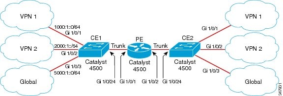
Configuring CE1 Switch

ipv6 unicast-routing
vrf definition v1
rd 100:1
!
address-family ipv6
exit-address-family
!
 
vrf definition v2
rd 200:1
!
address-family ipv6
exit-address-family
!
 
interface Vlan100
vrf forwarding v1
no ip address
ipv6 address 1000:1::1/64
ospfv3 100 ipv6 area 0
!
 
interface Vlan200
vrf forwarding v2
no ip address
ipv6 address 2000:1::1/64
ospfv3 200 ipv6 area 0
!
 
interface GigabitEthernet 1/0/1
switchport access vlan 100
end
 
interface GigabitEthernet 1/0/2
switchport access vlan 200
end
 
interface GigabitEthernet 1/0/24
switchport trunk encapsulation dot1q
 
switchport mode trunk
no ip address
end
 
router ospfv3 100
router-id 10.10.10.10
!
address-family ipv6 unicast vrf v1
redistribute connected
area 0 normal
exit-address-family
!
 
router ospfv3 200
router-id 20.20.20.20
!
address-family ipv6 unicast vrf v2
redistribute connected
area 0 normal
exit-address-family
!

Configuring PE Switch

ipv6 unicast-routing
 
vrf definition v1
rd 100:1
!
address-family ipv6
exit-address-family
!
 
vrf definition v2
rd 200:1
!
address-family ipv6
exit-address-family
!
interface Vlan600
vrf forwarding v1
no ip address
ipv6 address 1000:1::2/64
ospfv3 100 ipv6 area 0
!
 
interface Vlan700
vrf forwarding v2
no ip address
ipv6 address 2000:1::2/64
ospfv3 200 ipv6 area 0
!
 
interface Vlan800
vrf forwarding v1
no ip address
ipv6 address 3000:1::7/64
ospfv3 100 ipv6 area 0
!
interface Vlan900
vrf forwarding v2
no ip address
ipv6 address 4000:1::7/64
ospfv3 200 ipv6 area 0
!
 
interface GigabitEthernet 1/0/1
switchport trunk encapsulation dot1q
switchport mode trunk
no ip address
exit
 
interface GigabitEthernet 1/0/2
switchport trunk encapsulation dot1q
 
switchport mode trunk
no ip address
exit
 
router ospfv3 100
router-id 30.30.30.30
!
address-family ipv6 unicast vrf v1
redistribute connected
area 0 normal
exit-address-family
!
address-family ipv6 unicast vrf v2
redistribute connected
area 0 normal
exit-address-family
!

Configuring CE2 Switch

ipv6 unicast-routing
 
vrf definition v1
rd 100:1
!
address-family ipv6
exit-address-family
!
 
vrf definition v2
rd 200:1
!
address-family ipv6
exit-address-family
!
 
interface Vlan100
vrf forwarding v1
no ip address
 
ipv6 address 1000:1::3/64
ospfv3 100 ipv6 area 0
!
 
interface Vlan200
vrf forwarding v2
no ip address
ipv6 address 2000:1::3/64
ospfv3 200 ipv6 area 0
!
 
interface GigabitEthernet 1/0/1
switchport access vlan 100
end
 
interface GigabitEthernet 1/0/2
switchport access vlan 200
end
 
interface GigabitEthernet 1/0/24
switchport trunk encapsulation dot1q
switchport mode trunk
end
 
router ospfv3 100
router-id 40.40.40.40
!
address-family ipv6 unicast vrf v1
redistribute connected
area 0 normal
exit-address-family
!
 
router ospfv3 200
router-id 50.50.50.50
!
address-family ipv6 unicast vrf v2
redistribute connected
 
area 0 normal
exit-address-family
!

Displaying VRF-lite Status

To display information about VRF-lite configuration and status, perform one of the following tasks:

note.gif

Noteblank.gif For more information about the information in the displays, refer to the Cisco IOS Switching Services Command Reference at:

http://www.cisco.com/en/US/docs/ios/ipswitch/command/reference/isw_book.html


To display information about VRF-lite configuration and status, perform one of the following tasks:


Command
Purpose

Switch# show ipv6 route vrf a [X:X:X:X::X/<0-128>] [bgp] [connected] [eigrp] [interface] [isis] [local] [nd] [nsf] [ospf ] [repair] [rip] [shortcut] [static] [summary] [tag] [updated] [watch]

Displays routing protocol information associated with a VRF.

X:X:X:X::X/<0-128> IPv6 prefix
bgp BGP routes
connected Connected routes
eigrp EIGRP routes
interface interface specific routes
isis IS-IS routes
local Local routes
nd ND routes
nsf non stop forwarding state
ospf OSPFv3 routes
repair Routes with Repair paths
rip RIPng routes
shortcut Routes with Shortcut paths
static Static routes
summary Summary display
tag Route Tag
updated Show routes with timestamps
watch route watchers

Switch# show ipv6 vrf [brief | detail | interfaces] [vrf-name]

Displays information about the defined VRF instances.

brief Brief VPN Routing/Forwarding instance information

detail Detailed VPN Routing/Forwarding instance information

interfaces Show VPN Routing/Forwarding interface information

When you configure VRF table “a” with the IPv6 address family and attach the VRF to the interface with IPv6 address 1::2/64, the show ipv6 route vrf a command displays the following output:

Switch# show ipv6 route vrf a
IPv6 Routing Table - a - 3 entries
Codes: C - Connected, L - Local, S - Static, U - Per-user Static route
B - BGP, R - RIP, I1 - ISIS L1, I2 - ISIS L2
IA - ISIS interarea, IS - ISIS summary, D - EIGRP, EX - EIGRP external
ND - ND Default, NDp - ND Prefix, DCE - Destination, NDr - Redirect
O - OSPF Intra, OI - OSPF Inter, OE1 - OSPF ext 1, OE2 - OSPF ext 2
ON1 - OSPF NSSA ext 1, ON2 - OSPF NSSA ext 2
C 1::/64 [0/0]
via GigabitEthernet7/1, directly connected
L 1::2/128 [0/0]
via GigabitEthernet7/1, receive
L FF00::/8 [0/0]
via Null0, receive
Switch#
 

For further examples, refer to

http://www.cisco.com/en/US/docs/ios/ipv6/command/reference/ipv6_16.html

Configuring IPv6 VRF-lite

Beginning with Release IOS XE 3.5.0E and IOS 15.2(1)E, to support IPv6 VRF-lite, we transition from the ip vrf command to the “new” vrf definition command.

Configure VRFs

To configure one or more VRFs, perform this task:


Command
Purpose

Step 1

Switch# configure terminal

Enters global configuration mode.

Step 2

Switch(config)# ipv6 routing

Enables IPv6 routing.

Step 3

Switch(config)# vrf definition vrf-name

Names the VRF and enters VRF configuration mode.

Step 4

Switch(config-vrf)# address-family ipv4 | ipv6

(Optional) IPv4 by default. Configuration MUST for ipv6.

Step 5

Switch(config-vrf)# rd route-distinguisher

(Optional) Creates a VRF table by specifying a route distinguisher. Enter either an Autonomous System number and an arbitrary number (xxx:y) or an IP address and arbitrary number (A.B.C.D:y).

Step 6

Switch(config-vrf)# route-target { export | import | both } route-target-ext-community

(Optional) Creates a list of import, export, or import and export route target communities for the specified VRF. Enter either an AS system number and an arbitrary number (xxx:y) or an IP address and an arbitrary number (A.B.C.D:y).

Note This command is effective only if BGP is running.

Step 7

Switch(config-vrf)# import map route-map

(Optional) Associates a route map with the VRF.

Step 8

Switch(config-vrf)# interface interface-id

Enters interface configuration mode and specify the Layer 3 interface to be associated with the VRF. The interface can be a routed port or SVI.

Step 9

Switch(config-if)# ip vrf forwarding vrf-name

Associates the VRF with the Layer 3 interface.

Step 10

Switch(config-if)# end

Returns to privileged EXEC mode.

Step 11

Switch# show ip vrf [brief | detail | interfaces] [vrf-name]

Verifies the configuration. Displays information about the configured VRFs.

Step 12

Switch# copy running-config startup-config

(Optional) Saves your entries in the configuration file.

This example shows how to configure VRFs:

Switch(config)# vrf definition red
Switch(config-vrf)# rd 100:1
Switch(config-vrf)# address family ipv6
Switch(config-vrf-af)# route-target both 200:1
Switch(config-vrf)# exit-address-family
Switch(config-vrf)# interface Ethernet0/1
Switch(config-if)# vrf forwarding red
Switch(config-if)# ipv6 address 5000::72B/64

Associate Interfaces to the Defined VRFs

To associate interface to the defined VRFs, perform this task:


Command
Purpose

Step 1

Switch(config)# vrf configuration

Enters vrf configuration mode.

Step 1

Switch(config-vrf)# interface interface-id

Enters interface configuration mode and specifies the Layer 3 interface to be associated with the VRF. The interface can be a routed port or SVI.

Step 2

Switch(config-if)# vrf forwarding vrf-name

Associates the VRF with the Layer 3 interface.

Step 3

Switch(config-if)# end

Returns to privileged EXEC mode.

Step 4

Switch# show ipv6 vrf [brief | detail | interfaces] [vrf-name]

Verifies the configuration. Displays information about the configured VRFs.

Step 5

Switch# copy running-config startup-config

(Optional) Saves your entries in the configuration file.

This example shows how to associate an interface to VRFs:

Switch(config-vrf)# interface ethernet0/1
Switch(config-if)# vrf forwarding red
Switch(config-if)# ipv6 address 5000::72B/64

Populate VRF with Routes via Routing Protocols

Static Route


Command
Purpose

Step 1

ipv6 route [vrf vrf-name] ipv6-prefix/prefix-length {ipv6-address | interface-type interface-number [ipv6-address]}

To configure static routes specific to VRF.

This example shows how to populate VRF with a static route:

Switch(config)# ipv6 route vrf v6a 7000::/64 TenGigabitEthernet3/2 4000::2

Routing Protocols

OSPFv3

To configure the OSPFv3 router process and the IPv6 address family in OSPFv3, perform the following steps:


Command
Purpose

Step 1

Switch> enable

Enters privileged EXEC mode.

Enter your password if prompted.

Step 2

Switch# configure terminal

Enters global configuration mode.

Step 3

Switch(config)# router ospfv3 process-id

Enables OSPFv3 router configuration mode for the IPv4 or IPv6 address family.

Step 4

Switch(config-router)# area area-ID [default-cot | nssa | stub]

Configures the OSPFv3 area.

Step 5

Switch(config-router)# router-id router-id

Use a fixed router ID.

Step 6

Switch(config-router)# address-family ipv6 unicast vrf vrf-name

Or

Switch(config-router)# address-family ipv4 unicast

Enters IPv6 address family configuration mode for OSPFv3 in VRF vrf-name

or

Enters IPv4 address family configuration mode for OSPFv3.

Step 7

Switch(config-router)# redistribute source-protocol [process-id] options

Redistributes IPv6 and IPv4 routes from one routing domain into another routing domain.

Step 8

Switch(config-router)# end

Returns to privileged EXEC mode.

This example shows how configure the OSPFv3 router process:

Switch(config-router)# router ospfv3 1
Switch(config-router)# router-id 1.1.1.1
Switch(config-router)# address-family ipv6 unicast
Switch(config-router-af)# exit-address-family
 

To enable OSPFv3 on an interface, do the following:


Command
Purpose

Step 1

Switch> enable

Enters privileged EXEC mode.

Enter your password if prompted.

Step 2

Switch# configure terminal

Enters global configuration mode.

Step 3

Switch(config)# interface type-number

Specifies an interface type and number, and places the switch in interface configuration mode.

Step 4

Switch(config-if)# ospfv3 process-id area area-ID {ipv4 | ipv6} [instance instance-id]

Or

Switch(config-if)# ipv6 ospf process-id area area-ID [instance instance-id]

Enables OSPFv3 on an interface with the IPv4 or IPv6 AF.


or

Enables OSPFv3 on an interface.

Step 5

Switch(config-if)# end

Returns to privileged EXEC mode.

This example show how to enable OSPFv3 on an interface:

Switch(config)# interface GigabitEthernet2/1
Switch(config-if)# no switchport
Switch(config-if)# ipv6 address 4000::2/64
Switch(config-if)# ipv6 enable
Switch(config-if)# ipv6 ospf 1 area 0
Switch(config-if)# end

EIGRP

To configure an EIGRPv6 routing process, perform the following steps:


Command
Purpose

Step 1

Switch> enable

Enters privileged EXEC mode.

Enter your password if prompted.

Step 2

Switch# configure terminal

Enters global configuration mode.

Step 3

Switch(config)# router eigrp virtual-instance-name

Configures the EIGRP routing process and enters router configuration mode.

Step 4

Switch(config-router)# address-family ipv6 vrf vrf-name autonomous-system autonomous-system-number

Enables EIGRP IPv6 VRF-Lite and enters address family configuration mode.

Step 5

Switch(config-router-af)# topology {base | topology-name tid number

Configures an EIGRP process to route IP traffic under the specified topology instance and enters address family topology configuration mode.

Step 6

Switch(config-router-af-topology)# exit-aftopology

Exits address family topology configuration mode.

Step 7

Switch(config-router)# eigrp router-id ip-address

Enables the use of a fixed router-id.

Step 8

Switch(config-router)# end

Exits router configuration mode.

This example shows how to configure an EIGRP routing process:

Switch(config)# router eigrp test
Switch(config-router)# address-family ipv6 unicast vrf b1 autonomous-system 10
Switch(config-router-af)# topology base
Switch(config-router-af-topology)# exit-af-topology
Switch(config-router)# eigrp router-id 2.3.4.5
Switch(config-router)# exit-address-family

EBGPv6

To configure EBGPv6, do the following:


Command
Purpose

Step 1

Switch> enable

Enters privileged EXEC mode.

Enter your password if prompted.

Step 2

Switch# configure terminal

Enters global configuration mode.

Step 3

Switch(config)# router bgp as-number

Enters router configuration mode for the specified routing process.

Step 4

Switch(config-router)# neighbor peer-group-name peer-group

Creates a multiprotocol BGP peer group.

Step 5

Switch(config-router)# neighbor {ip-address | ipv6-address[%] | peer-group-name}remote-as autonomous-system-number [alternate-as autonomous-system-number...]

Adds the IPv6 address of the neighbor in the specified autonomous system to the IPv6 multiprotocol BGP neighbor table of the local router.

Step 6

Switch(config-router)# address-family ipv6 [vrf vrf-name] [unicast | multicast | vpnv6]

Specifies the IPv6 address family, and enters address family configuration mode.

  • The unicast keyword specifies the IPv6 unicast address family. By default, the switch is placed in configuration mode for the IPv6 unicast address family if theunicast keyword is not specified with the address-family ipv6command.
  • The multicast keyword specifies IPv6 multicast address prefixes.

Step 7

Switch(config-router-af)# neighbor ipv6-address peer-group peer-group-name

Assigns the IPv6 address of a BGP neighbor to a peer group.

Step 8

Switch(config-router-af)# neighbor {ip-address | peer-group-name | ipv6-address[%]}route-map map-name {in | out}

Applies a route map to incoming or outgoing routes.

  • Changes to the route map will not take effect for existing peers until the peering is reset or a soft reset is performed. Using the clear bgp ipv6 command with the soft and in keywords will perform a soft reset.

Step 9

Switch(config-router-af)# exit

Exits address familyconfiguration mode, and returns the router to router configuration mode.

This example shows how to configure EBRPv6:

Switch(config)# router bgp 2
Switch(config-router)# bgp router-id 2.2.2.2
Switch(config-router)# bgp log-neighbor-changes
Switch(config-router)# no bgp default ipv4-unicast
Switch(config-router)# neighbor 2500::1 remote-as 1
Switch(config-router)# neighbor 4000::2 remote-as 3
Switch(config-router)# address-family ipv6 vrf b1
Switch(config-router-af)# network 2500::/64
Switch(config-router-af)# network 4000::/64
Switch(config-router-af)# neighbor 2500::1 remote-as 1
Switch(config-router-af)# neighbor 2500::1 activate
Switch(config-router-af)# neighbor 4000::2 remote-as 3
Switch(config-router-af)# neighbor 4000::2 activate
Switch(config-router-af)# exit-address-family

VPN Co-existence Between IPv4 and IPv6

With Release IOS XE 3.5.0E and IOS 15.2(1)E, we provide backward compatibility between the “older” CLI for configuring IPv4 and the “new” CLI for IPv6. This means that a configuration might contain both CLI. The IPv4 CLI retains the ability to have on the same interface, an IP address defined within a VRF as well as an IPv6 address defined in the global routing table.

For example:

vrf definition red
rd 100:1
address family ipv6
route-target both 200:1
exit-address-family
!
ip vrf blue
rd 200:1
route-target both 200:1
!
interface Ethernet0/0
vrf forwarding red
ip address 50.1.1.2 255.255.255.0
ipv6 address 4000::72B/64
!
interface Ethernet0/1
ip vrf forwarding blue
ip address 60.1.1.2 255.255.255.0
ipv6 address 5000::72B/64
 

In this example, all addresses (v4 and v6) defined for Ethernet0/0 refer to VRF red whereas for Ethernet0/1, the IP address refers to VRF blue but the ipv6 address refers to the global IPv6 routing table.

Migrating from the Old to New CLI Scheme

Prior to Release IOS XE 3.5.0E and IOS 15.2(1)E, you used the ip vrf command to configure vrf. With Release IOS XE 3.5.0E and IOS 15.2(1)E, you use the new vrf definition command.

Henceforward, to incorporate IPv6 VRf configurations in addition to IPv4 configurations, you must migrate from the prior VRF CLI scheme using the following command:

Switch(config)# vrf upgrade-cli multi-af-mode {common-policies | non-common-policies} [vrf name]

This command forces migration from old CLI for IPv4 VRF to the new VRF multi-AF CLI. It is not nvgen'd because the effect is “one-time” only (see BGP similar command " bgp upgrade-cli ").