Catalyst 4948E and Catalyst 4948E-F Switch Installation Guide
Bias-Free Language
The documentation set for this product strives to use bias-free language. For the purposes of this documentation set, bias-free is defined as language that does not imply discrimination based on age, disability, gender, racial identity, ethnic identity, sexual orientation, socioeconomic status, and intersectionality. Exceptions may be present in the documentation due to language that is hardcoded in the user interfaces of the product software, language used based on RFP documentation, or language that is used by a referenced third-party product. Learn more about how Cisco is using Inclusive Language.
- Updated:
- January 4, 2012
Chapter: Transceivers
Transceiver, Chassis Connectors, and Cable and Adapter Specifications
This appendix covers the transceivers supported by the Catalyst 4948E and the Catalyst 4948E-F switches, the connectors on the front panel of the chassis, and the cables and adapters supplied in the accessory kit. The appendix is divided into the following topics:
•![]() Transceiver Support for Uplink Ports
Transceiver Support for Uplink Ports

Tip ![]() For additional information about the Cisco Catalyst 4948E and the Catalyst 4948E-F switches (including configuration examples and troubleshooting information), see the documents listed on this page:
For additional information about the Cisco Catalyst 4948E and the Catalyst 4948E-F switches (including configuration examples and troubleshooting information), see the documents listed on this page:
http://www.cisco.com/en/US/products/ps6021/tsd_products_support_series_home.html
Transceiver Support for Uplink Ports
Both the Catalyst 4948E and the Catalyst 4948E-F chassis have four uplink ports that support both 1-GB SFP and 10-GB SFP+ transceivers.
1-GB SFP Transceivers
Table B-1 lists the 1-GB SFP transceivers that are supported on the chassis uplink ports.
The four uplink ports also support 1-GB CWDM and 1-GB DWDM SFP transceivers, which are described in separate sections.
Figure B-1 shows a 1000BASE-X (optical) SFP transceiver with the major features of the transceiver identified. Figure B-2 shows a 1000BASE-T (copper) SFP transceiver with the major features of the transceiver identified.
Figure B-1 1-GB Optical SFP Transceiver Features
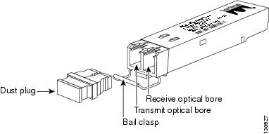
Figure B-2 1-GB Copper SFP Transceiver Features

|
|
RJ-45 connector |
|
Bail-clasp shown in the open (unlocked) position |
|
|
Bail-clasp shown in the closed (locked) position |
Table B-2 lists the specifications for the 1000BASE-T and 1000BASE-X SFP transceivers.
|
|
|
|
|
|
|
|
|---|---|---|---|---|---|---|
1000BASE-T |
RJ-45 |
— |
Category 5, 5e, or 6 UTP/FTP |
— |
— |
328 ft (100 m) |
1000BASE-SX |
LC duplex |
850 |
MMF |
62.5 |
160 |
722 ft (220 m) |
1000BASE-LX/LH |
LC duplex |
1300 |
MMF2 |
62.5 |
500 |
1804 ft (550 m) |
1000BASE-ZX |
LC duplex |
1550 |
SMF |
G.6523 |
— |
43.4 to 62 mi (70 to 100 km)4 |
1000BASE-BX10 |
LC single |
1490 |
SMF |
G.6523 |
— |
6.21 mi (10 km) |
1000BASE-BX10 |
LC single |
1310 |
SMF |
G.6523 |
— |
6.21 mi (10 km) |
1 Cable distances are based on fiber loss. Additional factors, such as the number of splices and the optical quality of the fiber, can affect cabling distances. 2 A mode-conditioning patch cord is required. Using an ordinary patch cord with MMF, 1000BASE-LX/LH SFP transceivers, and a short link distance can cause transceiver saturation, resulting in an elevated bit error rate (BER). When using the LX/LH SFP transceiver with 62.5-micron diameter MMF, you must also install a mode-conditioning patch cord between the SFP transceiver and the MMF cable on both the sending and receiving ends of the link. The mode-conditioning patch cord is required for link distances greater than 984 ft (300 m). 3 ITU-T G.652 SMF as specified by the IEEE 802.3z standard. 4 1000BASE-ZX SFP modules can reach up to 62 miles (100 km) by using dispersion-shifted SMF or low-attenuation SMF; the actual distance depends on the fiber quality, the number of splices, and the connectors. |
Table B-3 lists the fiber loss budgets for the 1000BASE-T and 1000BASE-X SFP transceivers.

Note ![]() For the GLC-ZX-SM, the minimum attenuation between the transmit bore (TX) and the receive bore (RX) is 8 db. When using short distances of single-mode fiber cable, you might need to insert an inline optical attenuator in the link to avoid overloading the receiver.
For the GLC-ZX-SM, the minimum attenuation between the transmit bore (TX) and the receive bore (RX) is 8 db. When using short distances of single-mode fiber cable, you might need to insert an inline optical attenuator in the link to avoid overloading the receiver.
Table B-4 lists the physical and environmental specifications for the 1-GB SFP transceivers.
Note ![]() You can use any combination of SFP modules that your Cisco device supports. The only restrictions are that each SFP port must match the wavelength specifications on the other end of the cable and that the cable must not exceed the stipulated cable length for reliable communications.
You can use any combination of SFP modules that your Cisco device supports. The only restrictions are that each SFP port must match the wavelength specifications on the other end of the cable and that the cable must not exceed the stipulated cable length for reliable communications.
CWDM SFP Transceivers
The four uplink ports on the switches also support CWDM SFP transceivers. The CWDM SFP transceiver uses an LC optical connector to connect to single-mode fiber-optic (SMF) cable. You can connect the CWDM SFPs to CWDM passive optical system optical add/drop multiplexer (OADM) modules or multiplexer/demultiplexer plug-in modules using single-mode fiber-optic cables. The supported CWDM SFP transceivers, their associated wavelengths, and their connector color codes are listed in Table B-5
Table B-6 lists the optical specifications for the CWDM SFP transceivers.
Table B-6 CWDM SFP Optical Specifications
Table B-7 lists the physical and environmental specifications for the CWDM SFP transceivers.
DWDM SFP Transceivers
The four uplink ports on both the Catalyst 4948E and the Catalyst 4948E-F switches also support DWDM SFP transceivers. The DWDM SFP transceiver uses an LC optical connector to connect to single-mode fiber-optic (SMF) cable. You can connect the DWDM SFPs to DWDM passive optical system optical add/drop multiplexer (OADM) modules or multiplexer/demultiplexer plug-in modules using single-mode fiber-optic cables. The supported CWDM SFP transceivers, their associated wavelengths, and their connector color codes are listed in Table B-8.
Table B-9 lists the DWDM SFP transceiver optical specifications.
|
|
|
|---|---|
Transmitter spectral width |
0.2 nm |
Transmitter optical output power |
• • |
Receiver optical input wavelength |
• • |
Receiver optical input power |
• • • |
1 Power-limited performance. 2 Noise-limited performance. |
Table B-10 lists the physical and environmental specifications for the DWDM SFP transceivers.
10-GB SFP+ Transceivers
The Small Form-Factor Pluggable, enhanced (SFP+) 10-Gigabit Ethernet transceiver module is a bidirectional transceiver. It has a 20-pin connector on the electrical interface and a duplex LC connector on the optical interface. The following SFP+ transceivers are supported in the uplink ports:
•![]() SFP-10G-SR
SFP-10G-SR
•![]() SFP-10G-LR
SFP-10G-LR
•![]() SFP-10G-LRM
SFP-10G-LRM
•![]() SFP-H10GB-CU1M
SFP-H10GB-CU1M
•![]() SFP-H10GB-CU3M
SFP-H10GB-CU3M
•![]() SFP-H10GB-CU5M
SFP-H10GB-CU5M
Figure B-3 shows an SFP+ optical transceiver with the major features identified. Figure B-4 shows a copper (twinax) transceiver.
Figure B-3 SFP+ Optical Transceiver
Figure B-4 shows the SFP+ copper (twinax) transceiver.
Figure B-4 SFP+ 10-Gigabit Ethernet Copper (Twinax) Transceiver

Note ![]() When switching from 1-GB SFPs to 10-GB SFP+ transceivers or from an SFP+ to an SFP, the chassis recognizes the change in speed and sets the port accordingly.
When switching from 1-GB SFPs to 10-GB SFP+ transceivers or from an SFP+ to an SFP, the chassis recognizes the change in speed and sets the port accordingly.
The 10-GB SFP+ transceiver cabling specifications are listed in Table B-11.
Table B-12 lists the SFP+ transceiver optical transmit and receive specifications.
Table B-13 lists the physical and environmental specifications for the 10-GB SFP+ transceivers.
Console Port
Both the Catalyst 4948E and the Catalyst 4948E-F switches can be accessed through a serial console port located on the chassis front panel. The console port is 10/100/1000BASE-T port that uses an RJ-45 connector. The console port allows you to access the switch either locally (with a console terminal or PC) or remotely (with a modem).
Table B-14 lists the console port pinouts.
The two-color LINK LED associated with the console port provides visual status for the port:
•![]() Green—Link is established
Green—Link is established
•![]() Amber—Administrative disabled
Amber—Administrative disabled
•![]() Off—No link is detected
Off—No link is detected
Ethernet Management Port
The Ethernet management port supports10/100/1000BASE-T Ethernet. It can autonegotiate to operate at any line speed (10, 100, 1000 Mbps); full and half duplex modes for 10 and 100 Mbps line speed, and only full duplex at 1000 Mbps. The Ethernet management port has an RJ-45 connector with an associated Link Status LED. Table B-15 lists the 10/100BASE-T port pinouts.
The two-color LINK LED associated with the Ethernet management port provides visual status for the port:
•![]() Green—Link is established.
Green—Link is established.
•![]() Amber—Administrative disabled.
Amber—Administrative disabled.
•![]() Off—No link is detected.
Off—No link is detected.
Cables and Adapters
One cable adapter plug is supplied in the accessory kit for both switches.
Note ![]() A console cable is not provided in the accessory kit. It can be ordered as an option.
A console cable is not provided in the accessory kit. It can be ordered as an option.
Rollover Cable
You can use an optional RJ-45 rollover cable and the supplied RJ-45/DSUB F/F adapter to connect the chassis console port to a computer running terminal emulation software. Table C-2 lists the pinouts for the console port, the RJ-45 rollover cable, and the RJ-45/DSUB F/F adapter.
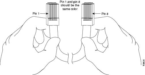
You can identify a rollover cable by comparing the two ends of the cable. Holding the cables side by side, with the tab at the back, the wire connected to the pin on the outside of the left plug should be the same color as the wire connected to the pin on the outside of the right plug. (See Figure B-5.) If your cable was purchased from Cisco Systems, pin 1 will be white on one connector, and pin 8 will be white on the other. (A rollover cable reverses pins 1 and 8, 2 and 7, 3 and 6, and 4 and 5.)
Figure B-5 Identifying a Rollover Cable
Rollover Cable RJ-45 to DB-9 Adapter (For Connecting to a PC)
Use an RJ-45-to-RJ-45 rollover cable and the RJ-45-to-DB-9 female DTE adapter (labeled Terminal) to connect the console port to a PC running terminal emulation software. Table B-16 lists the pinouts for the asynchronous serial console port, the RJ-45-to-RJ-45 rollover cable, and the RJ-45-to-DB-9 female DTE adapter.
|
|
|
|
|
|
|---|---|---|---|---|
Signal |
|
|
|
Signal |
RTS |
11 |
8 |
8 |
CTS |
DTR |
2 |
7 |
6 |
DSR |
TxD |
3 |
6 |
2 |
RxD |
GND |
4 |
5 |
5 |
GND |
GND |
5 |
4 |
5 |
GND |
RxD |
6 |
3 |
3 |
TxD |
DSR |
7 |
2 |
4 |
DTR |
CTS |
81 |
1 |
7 |
RTS |
1 Pin 1 is connected internally to Pin 8. |
 Feedback