- Index
- Preface
- Product Overview
- Command-Line Interfaces (CLI)
- Smart Port Macros
- Virtual Switching Systems (VSS)
- Fast Software Upgrades
- Stateful Switchover (SSO)
- Non-Stop Forwarding (NSF)
- RPR Supervisor Engine Redundancy
- Switch Fabric Functionality
- Interface Configuration
- UniDirectional Link Detection (UDLD)
- Power Management
- Environmental Monitoring
- Online Diagnostics
- Onboard Failure Logging (OBFL)
- Cisco IP Phone Support
- Power over Ethernet
- Layer 2 LAN Port Configuration
- Flex Links
- EtherChannels
- IEEE 802.1ak MVRP and MRP
- VLAN Trunking Protocol (VTP)
- VLANs
- Private VLANs (PVLANs)
- Private Hosts
- IEEE 802.1Q Tunneling
- Layer 2 Protocol Tunneling (L2PT)
- Spanning Tree Protocols (STP, MST)
- Optional STP Features
- IP Unicast Layer 3 Switching
- Policy-Based Routing (PBR)
- Layer 3 Interface Configuration
- Unidirectional Ethernet (UDE) and unidirectional link routing (UDLR)
- Multiprotocol Label Switching (MPLS)
- MPLS VPN Support
- Ethernet over MPLS (EoMPLS)
- Virtual Private LAN Services (VPLS)
- Ethernet Virtual Connections (EVC)
- Layer 2 over Multipoint GRE (L2omGRE)
- IPv4 Multicast Layer 3 Features
- IPv4 Multicast IGMP Snooping
- IPv4 PIM Snooping
- IPv4 Multicast VLAN Registration (MVR)
- IPv4 IGMP Filtering
- IPv4 Router Guard
- IPv4 Multicast VPN Support
- IPv6 Multicast Layer 3 Features
- IPv6 MLD Snooping
- NetFlow Hardware Support
- Call Home
- System Event Archive (SEA)
- Backplane Platform Monitoring
- Local SPAN, RSPAN, and ERSPAN
- SNMP IfIndex Persistence
- Top-N Reports
- Layer 2 Traceroute Utility
- Mini Protocol Analyzer
- PFC QoS Overview
- PFC QoS Guidelines and Restrictions
- PFC QoS Classification, Marking, and Policing
- PFC QoS Policy Based Queueing
- PFC QoS Global and Interface Options
- AutoQoS
- MPLS QoS
- PFC QoS Statistics Data Export
- Cisco IOS ACL Support
- Cisco TrustSec (CTS)
- AutoSecure
- MAC Address-Based Traffic Blocking
- Port ACLs (PACLs)
- VLAN ACLs (VACLs)
- Policy-Based Forwarding (PBF)
- Denial of Service (DoS) Protection
- Control Plane Policing (CoPP)
- Dynamic Host Configuration Protocol (DHCP) Snooping
- IP Source Guard
- Dynamic ARP Inspection (DAI)
- Traffic Storm Control
- Unknown Unicast and Multicast Flood Control
- IEEE 802.1X Port-Based Authentication
- Web-Based Authentication
- Port Security
- Lawful Intercept
- Online Diagnostic Tests
- Migrating From a 12.2SX QoS Configuration
Optional STP Features
- PortFast
- Bridge Assurance
- BPDU Guard
- PortFast Edge BPDU Filtering
- UplinkFast
- BackboneFast
- EtherChannel Guard
- Root Guard
- Loop Guard
- PVST Simulation
- Verifying the Optional STP Features

Note ●![]() For complete syntax and usage information for the commands used in this chapter, see these publications:
For complete syntax and usage information for the commands used in this chapter, see these publications:
http://www.cisco.com/en/US/products/ps9536/prod_command_reference_list.html
- Cisco IOS Release 12.2SY supports only Ethernet interfaces. Cisco IOS Release 12.2SY does not support any WAN features or commands.
- For information on configuring the Spanning Tree Protocol (STP), see Chapter28, “Spanning Tree Protocols”
http://www.cisco.com/en/US/products/hw/switches/ps708/tsd_products_support_series_home.html
Participate in the Technical Documentation Ideas forum
PortFast
Information about PortFast
STP PortFast causes a Layer 2 LAN port configured as an access port to enter the forwarding state immediately, bypassing the listening and learning states. You can use PortFast on Layer 2 access ports connected to a single workstation or server to allow those devices to connect to the network immediately, instead of waiting for STP to converge. Interfaces connected to a single workstation or server should not receive bridge protocol data units (BPDUs). When configured for PortFast, a port is still running the spanning tree protocol. A PortFast enabled port can immediately transition to the blocking state if necessary (this could happen on receipt of a superior BPDU). PortFast can be enabled on trunk ports. PortFast can have an operational value that is different from the configured value.
You can specifically configure a port as either an edge port, a network port, or a normal port. An edge port, which is connected to a Layer 2 host, can be either an access port or a trunk port. A network port is connected only to a Layer 2 switch or bridge.
Enabling PortFast

Tip![]() Configure STP BPDU Guard along with STP PortFast to shut down STP PortFast-enabled ports if they receive a BPDU.
Configure STP BPDU Guard along with STP PortFast to shut down STP PortFast-enabled ports if they receive a BPDU.
Configuring the PortFast Default State
To configure the default PortFast state, perform this task:
Note ●![]() The default spanning tree port type is normal, meaning only that its topology is not specified.
The default spanning tree port type is normal, meaning only that its topology is not specified.
- If you configure a port connected to a Layer 2 switch or bridge as an edge port, you might create a bridging loop.
- If you mistakenly configure a port that is connected to a Layer 2 host as a spanning tree network port, the port will automatically move into the blocking state.
This example shows how to configure the default switch access port state to be edge:
Enabling PortFast on a Layer 2 Port
Enabling PortFast on a Layer 2 Access Port

—Workstations.
—Servers.
—Ports on routers that are not configured to support bridging.
To enable PortFast on a Layer 2 access port, perform this task:
This example shows how to enable and verify PortFast on an interface:
Enabling PortFast on a Layer 2 Network Port
To enable PortFast on a Layer 2 network port, perform this task:
This example shows how to enable and verify PortFast on an interface:
Bridge Assurance
Information about Bridge Assurance
You can use Bridge Assurance to protect against certain problems that can cause bridging loops in the network. Specifically, you use Bridge Assurance to protect against a unidirectional link failure or other software failure and a device that continues to forward data traffic when it is no longer running the spanning tree algorithm.
Bridge Assurance is enabled by default and can only be disabled globally. Also, Bridge Assurance is enabled only on spanning tree network ports that are point-to-point links. Finally, both ends of the link must have Bridge Assurance enabled. If the device on one side of the link has Bridge Assurance enabled and the device on the other side either does not support Bridge Assurance or does not have this feature enabled, the connecting port is blocked.
With Bridge Assurance enabled, BPDUs are sent out on all operational network ports, including alternate and backup ports, for each hello time period. If the port does not receive a BPDU for a specified period, the port moves into an inconsistent state (blocking). and is not used in the root port calculation. Once that port receives a BPDU, it resumes the normal spanning tree transitions.
Figure 29-1 shows a normal STP topology, and Figure 29-2 demonstrates a potential network problem when the device fails and you are not running Bridge Assurance.
Figure 29-1 Network with Normal STP Topology
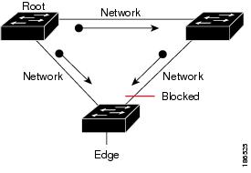
Figure 29-2 Network Problem without Running Bridge Assurance
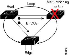
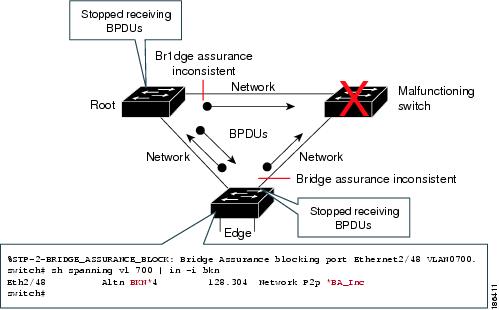
Figure 29-3 shows the network with Bridge Assurance enabled, and the STP topology progressing normally with bidirectional BPDUs issuing from every STP network port. Figure 29-4 shows how the potential network problem shown in Figure 29-2 does not happen when you have Bridge Assurance enabled on your network.
Figure 29-3 Network STP Topology Running Bridge Assurance
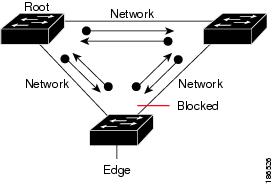
Figure 29-4 Network Problem Averted with Bridge Assurance Enabled
Enabling Bridge Assurance
By default, Bridge Assurance is enabled on all network ports on the switch. Disabling Bridge Assurance causes all configured network ports to behave as normal spanning tree ports. To enable or disable Bridge Assurance globally, perform this task:
|
|
|
|---|---|
Enables Bridge Assurance on all network ports on the switch. |
This example shows how to enable PortFast Bridge Assurance on all network ports on the switch, and how to configure a network port:
BPDU Guard
Information about BPDU Guard
When enabled on a port, BPDU Guard shuts down a port that receives a BPDU. When configured globally, BPDU Guard is only effective on ports in the operational PortFast (edge) state. In a valid configuration, PortFast Layer 2 LAN interfaces (edge ports) do not receive BPDUs. Reception of a BPDU by a PortFast Layer 2 LAN interface signals an invalid configuration, such as connection of an unauthorized device. BPDU Guard provides a secure response to invalid configurations, because the administrator must manually put the Layer 2 LAN interface back in service. BPDU Guard can be configured at the interface level. When configured at the interface level, BPDU Guard shuts the port down as soon as the port receives a BPDU, regardless of the PortFast configuration.
Note![]() When enabled globally, BPDU Guard applies to all interfaces that are in an operational PortFast (edge) state.
When enabled globally, BPDU Guard applies to all interfaces that are in an operational PortFast (edge) state.
Enabling BPDU Guard
Enabling BPDU Guard Globally
To enable BPDU Guard globally, perform this task:
|
|
|
|
|---|---|---|
Router(config)# spanning-tree portfast edge bpduguard default |
Enables BPDU Guard globally by default on all edge ports of the switch. |
|
This example shows how to enable BPDU Guard:
This example shows how to verify the configuration:
Enabling BPDU Guard on a Port
To enable BPDU Guard on a port, perform this task:
|
|
|
|
|---|---|---|
Router(config)# interface { type slot/port } | { port-channel port_channel_number } |
||
This example shows how to enable BPDU Guard:
PortFast Edge BPDU Filtering
Information about PortFast Edge BPDU Filtering
PortFast edge BPDU filtering allows the administrator to prevent the system from sending or even receiving BPDUs on specified ports.
When configured globally, PortFast edge BPDU filtering applies to all operational PortFast (edge) ports. Ports in an operational PortFast state are supposed to be connected to hosts, which typically drop BPDUs. If an operational PortFast port receives a BPDU, it immediately loses its operational PortFast status and becomes a normal port. In that case, PortFast edge BPDU filtering is disabled on this port and STP resumes sending BPDUs on this port.
PortFast edge BPDU filtering can also be configured on a per-port basis. When PortFast edge BPDU filtering is explicitly configured on a port, it does not send any BPDUs and drops all BPDUs it receives.
When you enable PortFast edge BPDU filtering globally and set the port configuration as the default for PortFast edge BPDU filtering (see the “Enabling PortFast Edge BPDU Filtering” section), then PortFast enables or disables PortFast edge BPDU filtering.
If the port configuration is not set to default, then the PortFast configuration will not affect PortFast edge BPDU filtering. Table 29-1 lists all the possible PortFast edge BPDU filtering combinations. PortFast edge BPDU filtering allows access ports to move directly to the forwarding state as soon as the end hosts are connected.
Enabling PortFast Edge BPDU Filtering
Enabling PortFast Edge BPDU Filtering Globally
To enable PortFast edge BPDU filtering globally, perform this task:
BPDU filtering is set to default on each edge port. This example shows how to enable PortFast edge BPDU filtering on the port and verify the configuration in PVST+ mode:
Enabling PortFast Edge BPDU Filtering on a Nontrunking Port
To enable or disable PortFast edge BPDU filtering on a nontrunking port, perform this task:
|
|
|
|
|---|---|---|
Router(config-if)# spanning-tree bpdufilter [ enable | disable ] |
||
This example shows how to enable PortFast edge BPDU filtering on a nontrunking port:
UplinkFast
Information about UplinkFast
UplinkFast provides fast convergence after a direct link failure and achieves load balancing between redundant Layer 2 links using uplink groups. An uplink group is a set of Layer 2 LAN interfaces (per VLAN), only one of which is forwarding at any given time. Specifically, an uplink group consists of the root port (which is forwarding) and a set of blocked ports, except for self-looping ports. The uplink group provides an alternate path in case the currently forwarding link fails.
Note![]() UplinkFast is most useful in wiring-closet switches. This feature may not be useful for other types of applications.
UplinkFast is most useful in wiring-closet switches. This feature may not be useful for other types of applications.
Figure 29-5 shows an example topology with no link failures. Switch A, the root bridge, is connected directly to Switch B over link L1 and to Switch C over link L2. The Layer 2 LAN interface on Switch C that is connected directly to Switch B is in the blocking state.
Figure 29-5 UplinkFast Example Before Direct Link Failure

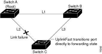
If Switch C detects a link failure on the currently active link L2 on the root port (a direct link failure), UplinkFast unblocks the blocked port on Switch C and transitions it to the forwarding state without going through the listening and learning states, as shown in Figure 29-6. This switchover takes approximately one to five seconds.
Figure 29-6 UplinkFast Example After Direct Link Failure
Enabling UplinkFast
UplinkFast increases the bridge priority to 49152 and adds 3000 to the STP port cost of all Layer 2 LAN ports on the switch, decreasing the probability that the switch will become the root bridge. UplinkFast cannot be enabled on VLANs that have been configured for bridge priority. To enable UplinkFast on a VLAN with bridge priority configured, restore the bridge priority on the VLAN to the default value by entering a no spanning-tree vlan vlan_ID priority command in global configuration mode.
Note![]() When you enable UplinkFast, it affects all VLANs on the switch. You cannot configure UplinkFast on an individual VLAN.
When you enable UplinkFast, it affects all VLANs on the switch. You cannot configure UplinkFast on an individual VLAN.
To enable UplinkFast, perform this task:
|
|
|
|
|---|---|---|
Router(config)# spanning-tree uplinkfast Router(config)# spanning-tree uplinkfast [ max-update-rate max_update_rate ] |
||
This example shows how to enable UplinkFast:
This example shows how to enable UplinkFast with an update rate of 400 packets per second:
This example shows how to verify that UplinkFast is enabled:
BackboneFast
Information about BackboneFast
BackboneFast is initiated when a root port or blocked port on a network device receives inferior BPDUs from its designated bridge. An inferior BPDU identifies one network device as both the root bridge and the designated bridge. When a network device receives an inferior BPDU, it indicates that a link to which the network device is not directly connected (an indirect link) has failed (that is, the designated bridge has lost its connection to the root bridge). Under normal STP rules, the network device ignores inferior BPDUs for the configured maximum aging time, as specified by the STP max-age command.
The network device tries to determine if it has an alternate path to the root bridge. If the inferior BPDU arrives on a blocked port, the root port and other blocked ports on the network device become alternate paths to the root bridge. (Self-looped ports are not considered alternate paths to the root bridge.) If the inferior BPDU arrives on the root port, all blocked ports become alternate paths to the root bridge. If the inferior BPDU arrives on the root port and there are no blocked ports, the network device assumes that it has lost connectivity to the root bridge, causes the maximum aging time on the root to expire, and becomes the root bridge according to normal STP rules.
If the network device has alternate paths to the root bridge, it uses these alternate paths to transmit a new kind of Protocol Data Unit (PDU) called the Root Link Query PDU. The network device sends the Root Link Query PDU out all alternate paths to the root bridge. If the network device determines that it still has an alternate path to the root, it causes the maximum aging time to expire on the ports on which it received the inferior BPDU. If all the alternate paths to the root bridge indicate that the network device has lost connectivity to the root bridge, the network device causes the maximum aging times on the ports on which it received an inferior BPDU to expire. If one or more alternate paths can still connect to the root bridge, the network device makes all ports on which it received an inferior BPDU its designated ports and moves them out of the blocking state (if they were in the blocking state), through the listening and learning states, and into the forwarding state.
Figure 29-7 shows an example topology with no link failures. Switch A, the root bridge, connects directly to Switch B over link L1 and to Switch C over link L2. The Layer 2 LAN interface on Switch C that connects directly to Switch B is in the blocking state.
Figure 29-7 BackboneFast Example Before Indirect Link Failure
If link L1 fails, Switch C cannot detect this failure because it is not connected directly to link L1. However, because Switch B is directly connected to the root bridge over L1, it detects the failure and elects itself the root and begins sending BPDUs to Switch C indicating itself as the root. When Switch C receives the inferior BPDUs from Switch B, Switch C infers that an indirect failure has occurred. At that point, BackboneFast allows the blocked port on Switch C to move immediately to the listening state without waiting for the maximum aging time for the port to expire. BackboneFast then transitions the Layer 2 LAN interface on Switch C to the forwarding state, providing a path from Switch B to Switch A. This switchover takes approximately 30 seconds, twice the Forward Delay time if the default Forward Delay time of 15 seconds is set. Figure 29-8 shows how BackboneFast reconfigures the topology to account for the failure of link L1.
Figure 29-8 BackboneFast Example After Indirect Link Failure

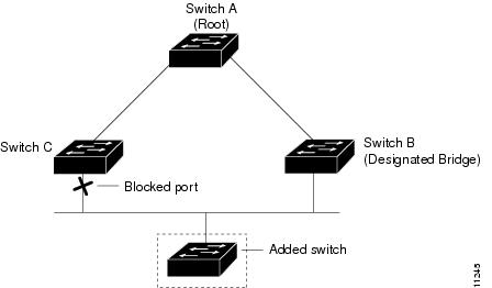
If a new network device is introduced into a shared-medium topology as shown in Figure 29-9, BackboneFast is not activated because the inferior BPDUs did not come from the recognized designated bridge (Switch B). The new network device begins sending inferior BPDUs that indicate that it is the root bridge. However, the other network devices ignore these inferior BPDUs and the new network device learns that Switch B is the designated bridge to Switch A, the root bridge.
Figure 29-9 Adding a Network Device in a Shared-Medium Topology
Enabling BackboneFast
Note![]() BackboneFast operates correctly only when enabled on all network devices in the network. BackboneFast is not supported on Token Ring VLANs. This feature is supported for use with third-party network devices.
BackboneFast operates correctly only when enabled on all network devices in the network. BackboneFast is not supported on Token Ring VLANs. This feature is supported for use with third-party network devices.
To enable BackboneFast, perform this task:
|
|
|
|
|---|---|---|
This example shows how to enable BackboneFast:
This example shows how to verify that BackboneFast is enabled:
EtherChannel Guard
Information about EtherChannel Guard
EtherChannel guard detects a misconfigured EtherChannel when interfaces on the switch are configured as an EtherChannel while interfaces on the other device are not or when not all the interfaces on the other device are in the same EtherChannel.
In response to misconfiguration detected on the other device, EtherChannel guard puts interfaces on the switch into the errdisabled state.
Enabling EtherChannel Guard
To enable EtherChannel guard, perform this task:
|
|
|
|
|---|---|---|
This example shows how to enable EtherChannel guard:
This example shows how to verify the configuration:
To display the interfaces that are in the errdisable state, enter the show interface status err-disable command.
After the misconfiguration has been cleared, interfaces in the errdisable state might automatically recover. To manually return a port to service, enter a shutdown and then a no shutdown command for the interface.
Root Guard
Information about Root Guard
The STP root guard feature prevents a port from becoming root port or blocked port. If a port configured for root guard receives a superior BPDU, the port immediately goes to the root-inconsistent (blocked) state.
Enabling Root Guard
To enable root guard, perform this task:
|
|
|
|
|---|---|---|
Router(config)# interface { type slot/port } | { port-channel port_channel_number } |
||
To display ports that are in the root-inconsistent state, enter the show spanning-tree inconsistentports command.
Loop Guard
Information about Loop Guard
Loop guard helps prevent bridging loops that could occur because of a unidirectional link failure on a point-to-point link. When enabled globally, the loop guard applies to all point-to-point ports on the system. Loop guard detects root ports and blocked ports and ensures that they keep receiving BPDUs from their designated port on the segment. If a loop guard enabled root or blocked port stop a receiving BPDUs from its designated port, it transitions to the loop-inconsistent blocking state, assuming there is a physical link error on this port. The port recovers from this loop-inconsistent state as soon as it receives a BPDU.
You can enable loop guard on a per-port basis. When you enable loop guard, it is automatically applied to all of the active instances or VLANs to which that port belongs. When you disable loop guard, it is disabled for the specified ports. Disabling loop guard moves all loop-inconsistent ports to the listening state.
If you enable loop guard on a channel and the first link becomes unidirectional, loop guard blocks the entire channel until the affected port is removed from the channel. Figure 29-10 shows loop guard in a triangle switch configuration.
Figure 29-10 Triangle Switch Configuration with Loop Guard

Figure 29-10 illustrates the following configuration:
- Switches A and B are distribution switches.
- Switch C is an access switch.
- Loop guard is enabled on ports 3/1 and 3/2 on Switches A, B, and C.
Enabling loop guard on a root switch has no effect but provides protection when a root switch becomes a nonroot switch.
When using loop guard, follow these guidelines:
- You cannot enable loop guard on PortFast-enabled ports.
- You cannot enable loop guard if root guard is enabled.
Loop guard interacts with other features as follows:
- Loop guard does not affect the functionality of UplinkFast or BackboneFast.
- Enabling loop guard on ports that are not connected to a point-to-point link will not work.
- Root guard forces a port to be always designated as the root port. Loop guard is effective only if the port is a root port or an alternate port. You cannot enable loop guard and root guard on a port at the same time.
- Loop guard uses the ports known to spanning tree. Loop guard can take advantage of logical ports provided by the Port Aggregation Protocol (PAgP). However, to form a channel, all the physical ports grouped in the channel must have compatible configurations. PAgP enforces uniform configurations of root guard or loop guard on all the physical ports to form a channel.
These caveats apply to loop guard:
–![]() Spanning tree always chooses the first operational port in the channel to send the BPDUs. If that link becomes unidirectional, loop guard blocks the channel, even if other links in the channel are functioning properly.
Spanning tree always chooses the first operational port in the channel to send the BPDUs. If that link becomes unidirectional, loop guard blocks the channel, even if other links in the channel are functioning properly.
–![]() If a set of ports that are already blocked by loop guard are grouped together to form a channel, spanning tree loses all the state information for those ports and the new channel port may obtain the forwarding state with a designated role.
If a set of ports that are already blocked by loop guard are grouped together to form a channel, spanning tree loses all the state information for those ports and the new channel port may obtain the forwarding state with a designated role.
–![]() If a channel is blocked by loop guard and the channel breaks, spanning tree loses all the state information. The individual physical ports may obtain the forwarding state with the designated role, even if one or more of the links that formed the channel are unidirectional.
If a channel is blocked by loop guard and the channel breaks, spanning tree loses all the state information. The individual physical ports may obtain the forwarding state with the designated role, even if one or more of the links that formed the channel are unidirectional.
Note You can enable UniDirectional Link Detection (UDLD) to help isolate the link failure. A loop may occur until UDLD detects the failure, but loop guard will not be able to detect it.
Enabling Loop Guard
To enable loop guard globally on the switch, perform this task:
|
|
|
|
|---|---|---|
This example shows how to enable loop guard globally:
To enable loop guard on a port, perform this task:
|
|
|
|
|---|---|---|
Router(config)# interface { type slot/port } | { port-channel port_channel_number } |
||
This example shows how to enable loop guard:
This example shows how to verify the configuration:
PVST Simulation
Information about PVST Simulation
MST interoperates with Rapid PVST+ with no need for user configuration. The PVST simulation feature enables this seamless interoperability.
Note![]() PVST simulation is enabled by default when you enable MST. That is, by default, all interfaces on the device interoperate between MST and Rapid PVST+.
PVST simulation is enabled by default when you enable MST. That is, by default, all interfaces on the device interoperate between MST and Rapid PVST+.
You may want to control the connection between MST and Rapid PVST+ to protect against accidentally connecting an MST-enabled port to a port enabled to run Rapid PVST+. Because Rapid PVST+ is the default STP mode, you may encounter many Rapid PVST+ connections.
Disabling Rapid PVST+ simulation, which can be done per port or globally for the entire device, moves the MST-enabled port to the PVST peer inconsistent (blocking) state once it detects it is connected to a Rapid PVST+-enabled port. This port remains in the inconsistent state until the port stops receiving Shared Spanning Tree Protocol (SSTP) BPDUs, and then the port resumes the normal STP transition process.
The root bridge for all STP instances must all be in either the MST region or the Rapid PVST+ side. If the root bridge for all STP instances are not on one side or the other, the software moves the port into a PVST simulation-inconsistent state.
Note![]() We recommend that you put the root bridge for all STP instances in the MST region.
We recommend that you put the root bridge for all STP instances in the MST region.
Configuring PVST Simulation
Note![]() PVST simulation is enabled by default so that all interfaces on the device interoperate between MST and Rapid PVST+.
PVST simulation is enabled by default so that all interfaces on the device interoperate between MST and Rapid PVST+.
To prevent an accidental connection to a device that does not run MST as the default STP mode, you can disable PVST simulation. If you disable PVST simulation, the MST-enabled port moves to the blocking state once it detects it is connected to a Rapid PVST+-enabled port. This port remains in the inconsistent state until the port stops receiving BPDUs, and then the port resumes the normal STP transition process.
To enable or disable PVST simulation globally, enter the command using the global keyword, as shown in the following task:
To override the global PVST simulation setting for a port, enter the command in the interface command mode, as shown in the following task:
|
|
|
|
|---|---|---|
Enables this interface to automatically interoperate with a connected device that is running in Rapid PVST+ mode. |
This example shows how to prevent the switch from automatically interoperating with a connecting device that is running Rapid PVST+:
This example shows how to prevent a port from automatically interoperating with a connecting device that is running Rapid PVST+:
Verifying the Optional STP Features
Using the show spanning-tree Commands
You can view spanning tree status and configuration information, both global and port-level, using the show spanning-tree commands described in this section. To view spanning tree status and configuration information, enter one of the following commands:
Examples of the show spanning-tree Commands
This example displays the spanning-tree status with Bridge Assurance enabled but in the inconsistent state:
The following inconsistency messages can be appended to the Type field:
- *BA_Inc—Indicates that Bridge Assurance is in the inconsistent state.
- *PVST_Peer_Inc—Indicates that the port is in a peer type Inconsistent state.
- Dispute—Indicates that a dispute condition is detected.
This example shows the spanning-tree configuration summary:
Possible states for the Bridge Assurance field are as follows:
This example shows the spanning tree summary when PVST simulation is disabled in any STP mode:
Possible states for the PVST Simulation Default field are as follows:
This example shows the spanning tree summary totals:
This example shows the spanning-tree configuration details of an edge port:
This example shows the spanning-tree configuration details of a trunk port:
This example shows the spanning-tree configuration details of an edge port when a dispute condition has been detected:
This example shows the spanning tree portfast edge interface operational state for all the instances:
http://www.cisco.com/en/US/products/hw/switches/ps708/tsd_products_support_series_home.html
Participate in the Technical Documentation Ideas forum
 Feedback