Information About Performing Device Setup Configuration
Review the sections in this module before performing your initial device configuration tasks that include IP address assignments and DHCP autoconfiguration.
Device Boot Process
To start your device, you need to follow the procedures in the hardware installation guide for installing and powering on the device and setting up the initial device configuration.
The normal boot process involves the operation of the boot loader software and includes these activities:
-
Performs low-level CPU initialization. It initializes the CPU registers, which control where physical memory is mapped, its quantity, its speed, and so forth.
-
Performs power-on self-test (POST) for the CPU subsystem and tests the system DRAM.
-
Initializes the file systems on the system board.
-
Loads a default operating system software image into memory and boots up the device.
The boot loader provides access to the file systems before the operating system is loaded. Normally, the boot loader is used only to load, decompress, and start the operating system. After the boot loader gives the operating system control of the CPU, the boot loader is not active until the next system reset or power-on.
Before you can assign device information, make sure you have connected a PC or terminal to the console port or a PC to the Ethernet management port, and make sure you have configured the PC or terminal-emulation software baud rate and character format to match these of the device console port:
-
Baud rate default is 9600.
-
Data bits default is 8.

Note
If the data bits option is set to 8, set the parity option to none.
-
Stop bits default is 2 (minor).
-
Parity settings default is none.
Devices Information Assignment
You can assign IP information through the device setup program, through a DHCP server, or manually.
Use the device setup program if you want to be prompted for specific IP information. With this program, you can also configure a hostname and an enable secret password.
It gives you the option of assigning a Telnet password (to provide security during remote management) and configuring your switch as a command or member switch of a cluster or as a standalone switch.
Use a DHCP server for centralized control and automatic assignment of IP information after the server is configured.
Note |
If you are using DHCP, do not respond to any of the questions in the setup program until the device receives the dynamically assigned IP address and reads the configuration file. |
If you are an experienced user familiar with the device configuration steps, manually configure the device. Otherwise, use the setup program described in the Device Boot Process section.
Default Switch Information
|
Feature |
Default Setting |
|---|---|
|
IP address and subnet mask |
No IP address or subnet mask are defined. |
|
Default gateway |
No default gateway is defined. |
|
Enable secret password |
No password is defined. |
|
Hostname |
The factory-assigned default hostname is device. |
|
Telnet password |
No password is defined. |
|
Cluster command switch functionality |
Disabled. |
|
Cluster name |
No cluster name is defined. |
DHCP-Based Autoconfiguration Overview
DHCP provides configuration information to Internet hosts and internetworking devices. This protocol consists of two components: one for delivering configuration parameters from a DHCP server to a device and an operation for allocating network addresses to devices. DHCP is built on a client-server model, in which designated DHCP servers allocate network addresses and deliver configuration parameters to dynamically configured devices. The device can act as both a DHCP client and a DHCP server.
During DHCP-based autoconfiguration, your device (DHCP client) is automatically configured at startup with IP address information and a configuration file.
With DHCP-based autoconfiguration, no DHCP client-side configuration is needed on your device. However, you need to configure the DHCP server for various lease options associated with IP addresses.
If you want to use DHCP to relay the configuration file location on the network, you might also need to configure a Trivial File Transfer Protocol (TFTP) server and a Domain Name System (DNS) server.
The DHCP server for your device can be on the same LAN or on a different LAN than the device. If the DHCP server is running on a different LAN, you should configure a DHCP relay device between your device and the DHCP server. A relay device forwards broadcast traffic between two directly connected LANs. A router does not forward broadcast packets, but it forwards packets based on the destination IP address in the received packet.
DHCP-based autoconfiguration replaces the BOOTP client functionality on your device.
DHCP Client Request Process
When you boot up your device, the DHCP client is invoked and requests configuration information from a DHCP server when the configuration file is not present on the device. If the configuration file is present and the configuration includes the ip address dhcp interface configuration command on specific routed interfaces, the DHCP client is invoked and requests the IP address information for those interfaces.
This is the sequence of messages that are exchanged between the DHCP client and the DHCP server.
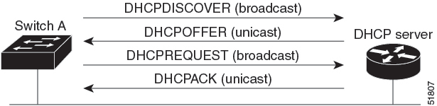
The client, Device A, broadcasts a DHCPDISCOVER message to locate a DHCP server. The DHCP server offers configuration parameters (such as an IP address, subnet mask, gateway IP address, DNS IP address, a lease for the IP address, and so forth) to the client in a DHCPOFFER unicast message.
In a DHCPREQUEST broadcast message, the client returns a formal request for the offered configuration information to the DHCP server. The formal request is broadcast so that all other DHCP servers that received the DHCPDISCOVER broadcast message from the client can reclaim the IP addresses that they offered to the client.
The DHCP server confirms that the IP address has been allocated to the client by returning a DHCPACK unicast message to the client. With this message, the client and server are bound, and the client uses configuration information received from the server. The amount of information the device receives depends on how you configure the DHCP server.
If the configuration parameters sent to the client in the DHCPOFFER unicast message are invalid (a configuration error exists), the client returns a DHCPDECLINE broadcast message to the DHCP server.
The DHCP server sends the client a DHCPNAK denial broadcast message, which means that the offered configuration parameters have not been assigned, that an error has occurred during the negotiation of the parameters, or that the client has been slow in responding to the DHCPOFFER message (the DHCP server assigned the parameters to another client).
A DHCP client might receive offers from multiple DHCP or BOOTP servers and can accept any of the offers; however, the client usually accepts the first offer it receives. The offer from the DHCP server is not a guarantee that the IP address is allocated to the client; however, the server usually reserves the address until the client has had a chance to formally request the address. If the device accepts replies from a BOOTP server and configures itself, the device broadcasts, instead of unicasts, TFTP requests to obtain the device configuration file.
The DHCP hostname option allows a group of devices to obtain hostnames and a standard configuration from the central management DHCP server. A client (device) includes in its DCHPDISCOVER message an option 12 field used to request a hostname and other configuration parameters from the DHCP server. The configuration files on all clients are identical except for their DHCP-obtained hostnames.
DHCP-based Autoconfiguration and Image Update
You can use the DHCP image upgrade features to configure a DHCP server to download both a new image and a new configuration file to one or more devices in a network. Simultaneous image and configuration upgrade for all switches in the network helps ensure that each new device added to a network receives the same image and configuration.
There are two types of DHCP image upgrades: DHCP autoconfiguration and DHCP auto-image update.
Restrictions for DHCP-based Autoconfiguration
-
The DHCP-based autoconfiguration with a saved configuration process stops if there is not at least one Layer 3 interface in an up state without an assigned IP address in the network.
-
Unless you configure a timeout, the DHCP-based autoconfiguration with a saved configuration feature tries indefinitely to download an IP address.
-
The auto-install process stops if a configuration file cannot be downloaded or if the configuration file is corrupted.
-
The configuration file that is downloaded from TFTP is merged with the existing configuration in the running configuration but is not saved in the NVRAM unless you enter the write memory or copy running-configuration startup-configuration privileged EXEC command. If the downloaded configuration is saved to the startup configuration, the feature is not triggered during subsequent system restarts.
DHCP Autoconfiguration
DHCP autoconfiguration downloads a configuration file to one or more devices in your network from a DHCP server. The downloaded configuration file becomes the running configuration of the device. It does not over write the bootup configuration saved in the flash, until you reload the device.
DHCP Auto-Image Update
You can use DHCP auto-image upgrade with DHCP autoconfiguration to download both a configuration and a new image to one or more devices in your network. The devices (or devices) downloading the new configuration and the new image can be blank (or only have a default factory configuration loaded).
If the new configuration is downloaded to a switch that already has a configuration, the downloaded configuration is appended to the configuration file stored on the switch. (Any existing configuration is not overwritten by the downloaded one.)
To enable a DHCP auto-image update on the device, the TFTP server where the image and configuration files are located must be configured with the correct option 67 (the configuration filename), option 66 (the DHCP server hostname) option 150 (the TFTP server address), and option 125 (description of the Cisco IOS image file) settings.
After you install the device in your network, the auto-image update feature starts. The downloaded configuration file is saved in the running configuration of the device, and the new image is downloaded and installed on the device. When you reboot the device, the configuration is stored in the saved configuration on the device.
DHCP Server Configuration Guidelines
Follow these guidelines if you are configuring a device as a DHCP server:
-
You should configure the DHCP server with reserved leases that are bound to each device by the device hardware address.
-
If you want the device to receive IP address information, you must configure the DHCP server with these lease options:
-
IP address of the client (required)
-
Subnet mask of the client (required)
-
DNS server IP address (optional)
-
Router IP address (default gateway address to be used by the device) (required)
-
-
If you want the device to receive the configuration file from a TFTP server, you must configure the DHCP server with these lease options:
-
TFTP server name (required)
-
Boot filename (the name of the configuration file that the client needs) (recommended)
-
Hostname (optional)
-
-
Depending on the settings of the DHCP server, the device can receive IP address information, the configuration file, or both.
-
If you do not configure the DHCP server with the lease options described previously, it replies to client requests with only those parameters that are configured. If the IP address and the subnet mask are not in the reply, the device is not configured. If the router IP address or the TFTP server name are not found, the device might send broadcast, instead of unicast, TFTP requests. Unavailability of other lease options does not affect autoconfiguration.
-
The device can act as a DHCP server. By default, the Cisco IOS DHCP server and relay agent features are enabled on your device but are not configured. (These features are not operational.)
Purpose of the TFTP Server
Based on the DHCP server configuration, the device attempts to download one or more configuration files from the TFTP server. If you configured the DHCP server to respond to the device with all the options required for IP connectivity to the TFTP server, and if you configured the DHCP server with a TFTP server name, address, and configuration filename, the device attempts to download the specified configuration file from the specified TFTP server.
If you did not specify the configuration filename, the TFTP server, or if the configuration file could not be downloaded, the device attempts to download a configuration file by using various combinations of filenames and TFTP server addresses. The files include the specified configuration filename (if any) and these files: network-config, cisconet.cfg, hostname.config, or hostname.cfg, where hostname is the device’s current hostname. The TFTP server addresses used include the specified TFTP server address (if any) and the broadcast address (255.255.255.255).
For the device to successfully download a configuration file, the TFTP server must contain one or more configuration files in its base directory. The files can include these files:
-
The configuration file named in the DHCP reply (the actual device configuration file).
-
The network-confg or the cisconet.cfg file (known as the default configuration files).
-
The router-confg or the ciscortr.cfg file (These files contain commands common to all device. Normally, if the DHCP and TFTP servers are properly configured, these files are not accessed.)
If you specify the TFTP server name in the DHCP server-lease database, you must also configure the TFTP server name-to-IP-address mapping in the DNS-server database.
If the TFTP server to be used is on a different LAN from the device, or if it is to be accessed by the device through the broadcast address (which occurs if the DHCP server response does not contain all the required information described previously), a relay must be configured to forward the TFTP packets to the TFTP server. The preferred solution is to configure the DHCP server with all the required information.
Purpose of the DNS Server
The DHCP server uses the DNS server to resolve the TFTP server name to an IP address. You must configure the TFTP server name-to-IP address map on the DNS server. The TFTP server contains the configuration files for the device.
You can configure the IP addresses of the DNS servers in the lease database of the DHCP server from where the DHCP replies will retrieve them. You can enter up to two DNS server IP addresses in the lease database.
The DNS server can be on the same LAN or on a different LAN from the device. If it is on a different LAN, the device must be able to access it through a router.
How to Obtain Configuration Files
Depending on the availability of the IP address and the configuration filename in the DHCP reserved lease, the device obtains its configuration information in these ways:
-
The IP address and the configuration filename is reserved for the device and provided in the DHCP reply (one-file read method).
The device receives its IP address, subnet mask, TFTP server address, and the configuration filename from the DHCP server. The device sends a unicast message to the TFTP server to retrieve the named configuration file from the base directory of the server and upon receipt, it completes its boot up process.
-
The IP address and the configuration filename is reserved for the device, but the TFTP server address is not provided in the DHCP reply (one-file read method).
The device receives its IP address, subnet mask, and the configuration filename from the DHCP server. The device sends a broadcast message to a TFTP server to retrieve the named configuration file from the base directory of the server, and upon receipt, it completes its boot-up process.
-
Only the IP address is reserved for the device and provided in the DHCP reply. The configuration filename is not provided (two-file read method).
The device receives its IP address, subnet mask, and the TFTP server address from the DHCP server. The device sends a unicast message to the TFTP server to retrieve the network-confg or cisconet.cfg default configuration file. (If the network-confg file cannot be read, the device reads the cisconet.cfg file.)
The default configuration file contains the hostnames-to-IP-address mapping for the device. The device fills its host table with the information in the file and obtains its hostname. If the hostname is not found in the file, the device uses the hostname in the DHCP reply. If the hostname is not specified in the DHCP reply, the device uses the default Switch as its hostname.
After obtaining its hostname from the default configuration file or the DHCP reply, the device reads the configuration file that has the same name as its hostname (hostname-confg or hostname.cfg, depending on whether network-confg or cisconet.cfg was read earlier) from the TFTP server. If the cisconet.cfg file is read, the filename of the host is truncated to eight characters.
If the device cannot read the network-confg, cisconet.cfg, or the hostname file, it reads the router-confg file. If the device cannot read the router-confg file, it reads the ciscortr.cfg file.
Note |
The device broadcasts TFTP server requests if the TFTP server is not obtained from the DHCP replies, if all attempts to read the configuration file through unicast transmissions fail, or if the TFTP server name cannot be resolved to an IP address. |
How to Control Environment Variables
With a normally operating device, you enter the boot loader mode only through the console connection configured for 9600 bps. Unplug the device power cord, and press the Mode button while reconnecting the power cord. The boot loader device prompt then appears.
The device boot loader software provides support for nonvolatile environment variables, which can be used to control how the boot loader, or any other software running on the system, operates. Boot loader environment variables are similar to environment variables that can be set on UNIX or DOS systems.
Environment variables that have values are stored in flash memory outside of the flash file system.
Each line in these files contains an environment variable name and an equal sign followed by the value of the variable. A variable has no value if it is not present; it has a value if it is listed even if the value is a null string. A variable that is set to a null string (for example, “ ”) is a variable with a value. Many environment variables are predefined and have default values.
You can change the settings of the environment variables by accessing the boot loader or by using Cisco IOS commands. Under normal circumstances, it is not necessary to alter the setting of the environment variables.
Common Environment Variables
This table describes the function of the most common environment variables.
|
Variable |
Boot Loader Command |
Cisco IOS Global Configuration Command |
|---|---|---|
|
BOOT |
set BOOT filesystem :/ file-url ... A semicolon-separated list of executable files to try to load and execute when automatically booting. |
boot system {filesystem : /file-url ... | switch {number | all}} Specifies the Cisco IOS image to load during the next boot cycle . This command changes the setting of the BOOT environment variable.
|
|
MANUAL_BOOT |
set MANUAL_BOOT yes Decides whether the switch automatically or manually boots. Valid values are 1, yes, 0, and no. If it is set to no or 0, the boot loader attempts to automatically boot up the system. If it is set to anything else, you must manually boot up the switch from the boot loader mode. |
boot manual Enables manually booting the switch during the next boot cycle and changes the setting of the MANUAL_BOOT environment variable. The next time you reboot the system, the switch is in boot loader mode. To boot up the system, use the boot flash: filesystem :/ file-url boot loader command, and specify the name of the bootable image. |
|
CONFIG_FILE |
set CONFIG_FILE flash:/ file-url Changes the filename that Cisco IOS uses to read and write a nonvolatile copy of the system configuration. |
boot config-file flash:/ file-url Specifies the filename that Cisco IOS uses to read and write a nonvolatile copy of the system configuration. This command changes the CONFIG_FILE environment variable. |
|
BAUD |
set BAUD baud-rate |
line console 0 speed speed-value Configures the baud rate. |
|
ENABLE_BREAK |
set ENABLE_BREAK yes/no |
boot enable-break switch yes/no Enables a break to the auto-boot cycle. You have 5 seconds to enter the break command. |
Environment Variables for TFTP
When the switch is connected to a PC through the Ethernet management port, you can download or upload a configuration file to the boot loader by using TFTP. Make sure the environment variables in this table are configured.
|
Variable |
Description |
||
|---|---|---|---|
|
MAC_ADDR |
Specifies the MAC address of the switch.
However, if you modify this variable after the boot loader is up or the value is different from the saved value, enter this command before using TFTP. A reset is required for the new value to take effect. |
||
|
IP_ADDRESS |
Specifies the IP address and the subnet mask for the associated IP subnet of the switch. |
||
|
DEFAULT_GATEWAY |
Specifies the IP address and subnet mask of the default gateway. |
Scheduled Reload of the Software Image
You can schedule a reload of the software image to occur on the device at a later time (for example, late at night or during the weekend when the device is used less), or you can synchronize a reload network-wide (for example, to perform a software upgrade on all device in the network).
Note |
A scheduled reload must take place within approximately 24 days. |
You have these reload options:
-
Reload of the software to take affect in the specified minutes or hours and minutes. The reload must take place within approximately 24 hours. You can specify the reason for the reload in a string up to 255 characters in length.
-
Reload of the software to take place at the specified time (using a 24-hour clock). If you specify the month and day, the reload is scheduled to take place at the specified time and date. If you do not specify the month and day, the reload takes place at the specified time on the current day (if the specified time is later than the current time) or on the next day (if the specified time is earlier than the current time). Specifying 00:00 schedules the reload for midnight.
The reload command halts the system. If the system is not set to manually boot up, it reboots itself.
If your device is configured for manual booting, do not reload it from a virtual terminal. This restriction prevents the device from entering the boot loader mode and then taking it from the remote user’s control.
If you modify your configuration file, the device prompts you to save the configuration before reloading. During the save operation, the system requests whether you want to proceed with the save if the CONFIG_FILE environment variable points to a startup configuration file that no longer exists. If you proceed in this situation, the system enters setup mode upon reload.
To cancel a previously scheduled reload, use the reload cancel privileged EXEC command.
 Feedback