The documentation set for this product strives to use bias-free language. For the purposes of this documentation set, bias-free is defined as language that does not imply discrimination based on age, disability, gender, racial identity, ethnic identity, sexual orientation, socioeconomic status, and intersectionality. Exceptions may be present in the documentation due to language that is hardcoded in the user interfaces of the product software, language used based on RFP documentation, or language that is used by a referenced third-party product. Learn more about how Cisco is using Inclusive Language.
Information About EVPN VXLAN Layer 2 Overlay Network
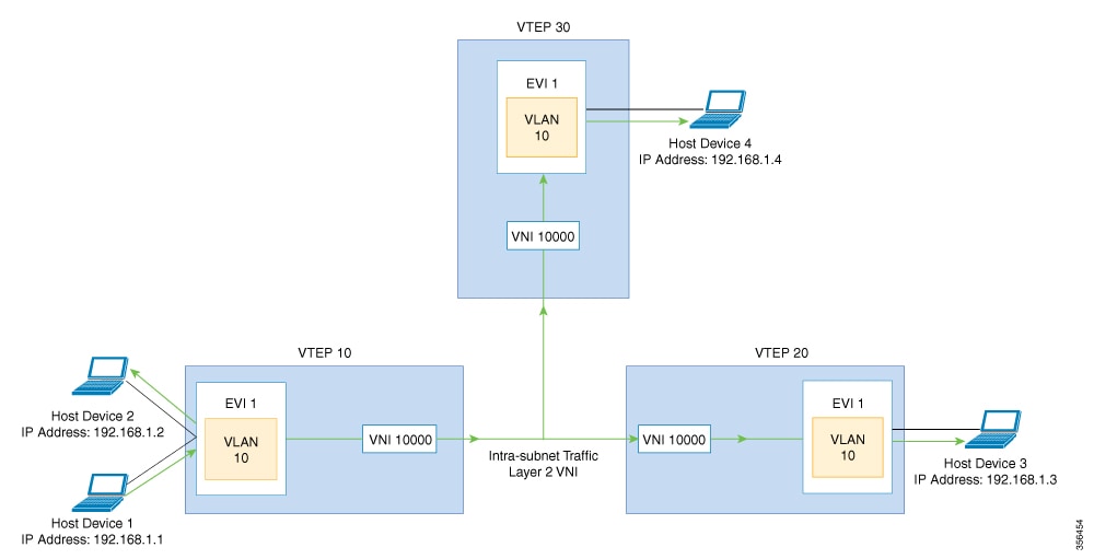
An EVPN VXLAN Layer 2 overlay network allows host devices in the same subnet to send bridged or Layer 2 traffic to each other.
The network forwards the bridged traffic using a Layer 2 virtual network instance (VNI).
Broadcast, Unknown Unicast, and Multicast Traffic
Multidestination Layer 2 traffic in a VXLAN network is typically referred to as broadcast, unknown unicast, and multicast
(BUM) traffic. In a BGP EVPN VXLAN fabric, the underlay network forwards the BUM traffic to all the endpoints connected to
a common Layer 2 broadcast domain in the VXLAN overlay.
The following image shows the flow of BUM traffic through a Layer 2 VNI. The network forwards BUM traffic from host device
1 to all the VTEPs which in turn send the traffic to all the host devices in the same subnet.
The MP-BGP EVPN control plane uses two different methods to forward BUM traffic in a VXLAN network:
Underlay Multicast
Ingress Replication
Underlay Multicast
In underlay multicast, the underlay network replicates the traffic through a multicast group. Forwarding BUM traffic using
underlay multicast requires the configuration of IP multicast in the underlay network. A single copy of the BUM traffic moves
from the ingress or source VTEP towards the underlay transport network. The network forwards this copy along the multicast
tree so that it reaches all egress or destination VTEPs participating in the given multicast group. Various branch points
in the network replicate the copy as it travels along the multicast tree. The branch points replicate the copy only if the
receivers are part of the multicast group associated with the VNI.
BUM traffic forwarding through underlay multicast is achieved by mapping a Layer 2 VNI to the multicast group. This mapping
must be configured on all the VTEPs associated with the Layer 2 VNI. When a VTEP joins the multicast group, it receives all
the traffic that is forwarded on that group. If the VTEP receives traffic in a VNI that is not associated with it, it simply
drops the traffic. This approach maintains a single link within the network, thus providing an efficient way to forward BUM
traffic.
Ingress Replication
Ingress replication, or headend replication, is a unicast approach to handle multidestination Layer 2 overlay BUM traffic.
Ingress replication involves an ingress device replicating every incoming BUM packet and sending them as a separate unicast
to the remote egress devices. Ingress replication happens through EVPN route type 3, also called as inclusive multicast ethernet
tag (IMET) route. BGP EVPN ingress replication uses IMET route for auto-discovery of remote peers in order to set up the BUM
tunnels over VXLAN. Using ingress replication to handle BUM traffic can result in scaling issues as an ingress device needs
to replicate the BUM traffic as many times as there are VTEPs associated with the Layer 2 VNI.
Ingress Replication Operation
IMET routes carry the remote or egress VNIs advertised from the remote peers, which can be different from the local VNI. The
network creates a VXLAN tunnel adjacency when an ingress device receives IMET ingress replication routes from remote NVE peers.
The tunnel adjacency is a midchain adjacency which contains IP or UDP encapsulation for the VXLAN Tunnel. If there is more
than one VNI along the tunnel, then multiple VNIs share the tunnel. Ingress replication on EVPN can have multiple unicast
tunnel adjacencies and different egress VNIs for each remote peer.
The network builds a flooded replication list with the routes advertised by each VTEP. The dynamic replication list stores
all the remote destination peers discovered on a BGP IMET route in the same Layer 2 VNI. The replication list gets updated
every time you configure the Layer 2 VNI at a remote peer. The network removes the tunnel adjacency and VXLAN encapsulation
from the replication list every time a remote NVE peer withdraws the IMET ingress replication route. The network deletes the
tunnel adjacency when there is no NVE peer using it.
Any BUM traffic that reaches the ingress device gets replicated after the replication list is built. The ingress device forwards
the replicated traffic throughout the network to all the remote peers in the same VNI.
How to Configure EVPN VXLAN Layer 2 Overlay Network
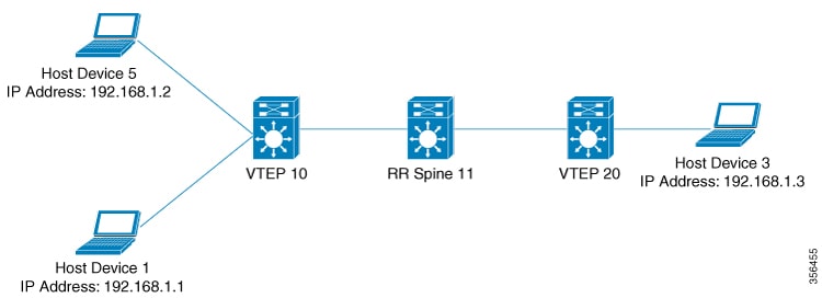
The following figure shows a sample topology of an EVPN VXLAN Network. Host device 1 and host device 3 are part of the same
subnet. The network forwards BUM traffic from host device 1 to host device 3 using a Layer 2 VNI through either underlay multicast
or ingress replication methods.
Note
In a two-VTEP topology, a spine switch is not mandatory. For information about configuration of spine switches in an EVPN
VXLAN network, see Configuring Spine Switches in a BGP EVPN VXLAN Fabric module.
Perform the following set of procedures to configure an EVPN VXLAN Layer 2 overlay network and forward the BUM traffic:
Configure Layer 2 VPN EVPN on the VTEPs.
Configure an EVPN instance in the VLAN on the VTEPs.
Configure the access-facing interface in the VLAN on the VTEPs.
Configure the loopback interface on the VTEPs.
Configure the network virtualization endpoint (NVE) interface on the VTEPs.
Configure BGP with EVPN address family on the VTEPs.
Configure underlay multicast, if the specified replication type is static. For more information, see IP Multicast Routing Configuration Guide.
Configuring Layer 2 VPN EVPN on a VTEP
To configure the Layer 2 VPN EVPN parameters on a VTEP, perform the following steps:
Procedure
Command or Action
Purpose
Step 1
enable
Example:
Device> enable
Enables privileged EXEC mode.
Enter your password, if prompted.
Step 2
configure terminal
Example:
Device# configure terminal
Enters global configuration mode.
Step 3
l2vpn evpn
Example:
Device(config)# l2vpn evpn
Enters EVPN configuration mode.
Step 4
replication-type { ingress | static}
Example:
Device(config-evpn)# replication-type static
Configures the Layer 2 VPN EVPN replication type.
Note
Configure the Layer 2 VPN EVPN replication type as static, if multicast is enabled in the underlay network for EVPN BUM traffic.
When the Layer 2 VPN EVPN replication type is configured as static, the IMET route is not advertised and forwarding of BUM
traffic relies on underlay multicast being configured on each VTEP.
Step 5
router-id loopback-interface-id
Example:
Device(config-evpn)# router-id loopback 0
Specifies the interface that will supply the IP addresses to be used in auto-generating route distinguishers.
Step 6
default-gateway advertise
Example:
Device(config-evpn)# default-gateway advertise
(Optional) Enables default gateway advertisement on the switch. To configure distributed anycast gateway in a VXLAN network
using MAC aliasing, enable default gateway advertisement on all the leaf switches in the network.
This command is applicable in integrated routing and bridging (IRB) scenarios where Layer 2 and Layer 3 VNIs coexist in a
VRF. Refer to Configuring EVPN VXLAN Integrated Routing and Bridging module for more details.
This command is mandatory only if the same MAC address is not manually configured on all the access SVIs.
Note
Use the default-gateway advertise { enable | disable} command in EVPN instnace configuration mode to override the global default gateway advertisement settings and enable or disable
it for a specific EVPN instance.
Step 7
logging peer state
Example:
Device(config-evpn)# logging peer state
(Optional) Displays syslog message when the first route is received or the last route is withdrawn from a given remote VTEP.
Step 8
mac duplication limit limit-number time time-limit
Example:
Device(config-evpn)# mac duplication limit 20 time 5
(Optional) Changes parameters for detecting duplicate MAC addresses.
Step 9
ip duplication limit limit-number time time-limit
Example:
Device(config-evpn)# ip duplication limit 20 time 5
(Optional) Changes parameters for detecting duplicate IP addresses.
Step 10
route-target auto vni
Example:
Device(config-evpn)# route-target auto vni
(Optional) Specifies to use VNI instead of EVPN instance number to auto-generate route target.
Step 11
exit
Example:
Device(config-evpn)# exit
Exits EVPN configuration mode and enters global configuration mode.
(Optional) Enables or disables the default gateway advertisement for the EVPN instance.
In case default gateway advertisement has already been globally configured, this overrides the global setting.
This command is mandatory only if the same MAC address is not manually configured on all the access SVIs.
To configure distributed anycast gateway in a VXLAN network using MAC aliasing, enable default gateway advertisement on all
the leaf switches in the network.
Step 16
ip local-learning { enable | disable}
Example:
Device(config-evpn-evi)# ip local-learning disable
(Optional) Enables or disables local IP address learning for the specified EVPN instance.
In case IP address learning has already been globally configured, this overrides the global setting.
Step 17
no auto-route-target
Example:
Device(config-evpn-evi)# no auto-route-target
(Optional) Disables auto generation of route targets.
Step 18
rd rd-value
Example:
Device(config-evpn-evi)# rd 65000:100
(Optional) Configures a route distinguisher manually.
Step 19
route-target { import | export | both} rt-value
Example:
Device(config-evpn-evi)# route-target both 65000:100
(Optional) Configures route targets manually.
Note
Configure route targets manually if the auto-generated route target values (ASN:EVI or ASN:VNI) are different between the
VTEPs.
Step 20
end
Example:
Device(config-evpn-evi)# end
Returns to privileged EXEC mode.
Configuring an EVPN Instance on the VLAN on a VTEP
To configure an EVPN instance on the VLAN on a VTEP, perform the following steps:
Procedure
Command or Action
Purpose
Step 1
enable
Example:
Device> enable
Enables privileged EXEC mode.
Enter your password, if prompted.
Step 2
configure terminal
Example:
Device# configure terminal
Enters global configuration mode.
Step 3
vlan configuration vlan-id
Example:
Device(config)# vlan configuration 11
Enters VLAN feature configuration mode for the specified VLAN interface.
Step 4
member evpn-instance evpn-instance-id vni l2-vni-number
Example:
Device(config-vlan)# member evpn-instance 1 vni 10000
Adds EVPN instance as a member of the VLAN configuration.
The VNI here is used as a Layer 2 VNI.
Step 5
end
Example:
Device(config-vlan)# end
Returns to privileged EXEC mode.
Configuring the Access-Facing Interface in the VLAN on a VTEP
To configure the access-facing interface in the VLAN on a VTEP, perform the following steps:
Procedure
Command or Action
Purpose
Step 1
enable
Example:
Device> enable
Enables privileged EXEC mode.
Enter your password, if prompted.
Step 2
configure terminal
Example:
Device# configure terminal
Enters global configuration mode.
Step 3
interface interface-name
Example:
Device(config)# interface GigabitEthernet1/0/1
Enters interface configuration mode for the specified interface.
Step 4
switchport access vlan vlan-id
Example:
Device(config-if)# switchport access vlan 11
Configures the interface as a static-access port of the specified VLAN.
Interface can also be configured as a trunk interface, if required.
Step 5
end
Example:
Device(config-if)# end
Returns to privileged EXEC mode.
Configuring the Loopback Interface on a VTEP
To configure the loopback interface on a VTEP, perform the following steps:
Procedure
Command or Action
Purpose
Step 1
enable
Example:
Device> enable
Enables privileged EXEC mode.
Enter your password, if prompted.
Step 2
configure terminal
Example:
Device# configure terminal
Enters global configuration mode.
Step 3
interface loopback-interface-id
Example:
Device(config)# interface Loopback0
Enters interface configuration mode for the specified Loopback interface.
Step 4
ip address ipv4-address
Example:
Device(config-if)# ip address 10.12.11.11
Configures the IP address for the Loopback interface.
Step 5
ip pim sparse mode
Example:
Device(config-if)# ip pim sparse mode
Enables Protocol Independent Multicast (PIM) sparse mode on the Loopback interface.
Step 6
end
Example:
Device(config-vlan)# end
Returns to privileged EXEC mode.
Configuring the NVE Interface on a VTEP
To add a VNI member to the NVE interface of a VTEP, perform the following steps:
Procedure
Command or Action
Purpose
Step 1
enable
Example:
Device> enable
Enables privileged EXEC mode.
Enter your password, if prompted.
Step 2
configure terminal
Example:
Device# configure terminal
Enters global configuration mode.
Step 3
interface nve-interface-id
Example:
Device(config)# interface nve1
Defines the interface to be configured as a trunk, and enters interface configuration mode.
Step 4
no ip address
Example:
Device(config-if)# no ip address
Disables IP processing on the interface by removing its IP address.
Step 5
source-interface loopback-interface-id
Example:
Device(config-if)# source-interface loopback0
Sets the IP address of the specified loopback interface as the source IP address.
Step 6
host-reachability protocol bgp
Example:
Device(config-if)# host-reachability protocol bgp
Configures BGP as the host-reachability protocol on the interface.
Step 7
member vni layer2-vni-id { ingress-replication | mcast-group multicast-group-address
Example:
Device(config-if)# member vni 10000 mcast-group 227.0.0.1
Associates the Layer 2 VNI member with the NVE.
The specified replication type must match the replication type that is configured globally or for the specific EVPN instance.
Use mcast-group keyword for static replication and ingress-replication keyword for ingress replication.
Step 8
end
Example:
Device(config-if)# end
Returns to privileged EXEC mode.
Configuring BGP on a VTEP with EVPN Address Family
To configure BGP on a VTEP with EVPN address family and with spine switch as the neighbor, perform the following steps:
Procedure
Command or Action
Purpose
Step 1
enable
Example:
Device> enable
Enables privileged EXEC mode.
Enter your password, if prompted.
Step 2
configure terminal
Example:
Device# configure terminal
Enters global configuration mode.
Step 3
router bgp autonomous-system-number
Example:
Device(config)# router bgp 1
Enables a BGP routing process, assigns it an autonomous system number, and enters router configuration mode.
Step 4
bgp log-neighbor-changes
Example:
Device(config-router)# bgp log-neighbor-changes
(Optional) Enables the generation of logging messages when the status of a BGP neighbor changes.
For more information, see Configuring BGP module of the IP Routing Configuration Guide.
Step 5
bgp update-delay time-period
Example:
Device(config-router)# bgp update-delay 1
(Optional) Sets the maximum initial delay period before sending the first update.
The range is 1 to 3600 seconds.
For more information, see Configuring BGP module of the IP Routing Configuration Guide.
Step 6
bgp graceful-restart
Example:
Device(config-router)# bgp graceful-restart
(Optional) Enables the BGP graceful restart capability for all BGP neighbors.
For more information, see Configuring BGP module of the IP Routing Configuration Guide.
Step 7
no bgp default ipv4-unicast
Example:
Device(config-router)# no bgp default ipv4-unicast
(Optional) Disables default IPv4 unicast address family for BGP peering session establishment.
For more information, see Configuring BGP module of the IP Routing Configuration Guide.
Enables the exchange information from a BGP neighbor.
Use the IP address of the spine switch as the neighbor IP address.
Step 12
neighbor ip-address send-community [ both | extended | standard]
Example:
Device(config-router-af)# neighbor 10.11.11.11 send-community both
Specifies the communities attribute sent to a BGP neighbor.
Use the IP address of the spine switch as the neighbor IP address.
Step 13
exit-address-family
Example:
Device(config-router-af)# exit-address-family
Exits address family configuration mode and returns to router configuration mode.
Step 14
end
Example:
Device(config-router)# end
Returns to privileged EXEC mode.
Configuration Examples for EVPN VXLAN Layer 2 Overlay Network
This section provides an example for configuring an EVPN VXLAN Layer 2 overlay network. This example shows a sample configuration
for a VXLAN network with 2 VTEPs, VTEP 1 and VTEP 2, connected to perform bridging.
Table 1. Configuration Example for a VXLAN Network with Two VTEPs Connected to Perform Bridging
VTEP 1
VTEP 2
VTEP1# show running-config
Building configuration...
!
hostname VTEP1
!
ip routing
ip multicast-routing
!
l2vpn evpn
 replication-type static
 router-id Loopback0
!
l2vpn evpn instance 1 vlan-based
 encapsulation vxlan
 route-target export 103:1
 route-target import 104:1
!
system mtu 9150
!
vlan configuration 201
 member evpn-instance 1 vni 6000
!
!
interface Loopback0
 ip address 10.1.1.10 255.255.255.255
 ip pim sparse-mode
!
!
interface GigabitEthernet1/0/1
description host1-interface
 switchport access vlan 201
 switchport mode access
!
!
interface GigabitEthernet1/0/29
 description core-underlay-interface
 no switchport
ip address 172.16.1.29 255.255.255.0
 ip pim sparse-mode
!
!
interface nve10
 no ip address
 source-interface Loopback0
 host-reachability protocol bgp
 member vni 6000 mcast-group 232.1.1.1
!
router ospf 1
 router-id 10.1.1.10
 network 10.1.1.0 0.0.0.255 area 0
 network 172.16.1.0 0.0.0.255 area 0
!
router bgp 10
 bgp router-id interface Loopback0
 bgp log-neighbor-changes
 bgp update-delay 1
 no bgp default ipv4-unicast
 neighbor 10.2.2.20 remote-as 10
 neighbor 10.2.2.20 update-source Loopback0
 !
 address-family ipv4
 exit-address-family
 !
 address-family l2vpn evpn
  neighbor 10.2.2.20 activate
  neighbor 10.2.2.20 send-community both
 exit-address-family
 !
ip pim rp-address 10.1.1.10
!
end
VTEP2# show running-config
Building configuration...
!
hostname VTEP2
!
ip routing
ip multicast-routing
!
l2vpn evpn
 replication-type static
 router-id Loopback0
!
l2vpn evpn instance 1 vlan-based
 encapsulation vxlan
 route-target export 104:1
 route-target import 103:1
!
system mtu 9150
!
vlan configuration 201
 member evpn-instance 1 vni 6000
!
!
interface Loopback0
 ip address 10.2.2.20 255.255.255.255
 ip pim sparse-mode
!
!
interface GigabitEthernet1/0/1
description host2-interface
 switchport access vlan 201
 switchport mode access
!
!
interface GigabitEthernet1/0/30
 description core-underlay-interface
 no switchport
 ip address 172.16.1.30 255.255.255.0
 ip pim sparse-mode
!
!
interface nve10
 no ip address
 source-interface Loopback0
 host-reachability protocol bgp
 member vni 6000 mcast-group 232.1.1.1
!
router ospf 1
 router-id 10.2.2.20
 network 10.2.2.0 0.0.0.255 area 0
 network 172.16.1.0 0.0.0.255 area 0
!
router bgp 10
 bgp router-id interface Loopback0
 bgp log-neighbor-changes
 bgp update-delay 1
 no bgp default ipv4-unicast
 neighbor 10.1.1.10 remote-as 10
 neighbor 10.1.1.10 update-source Loopback0
 !
 address-family ipv4
 exit-address-family
 !
 address-family l2vpn evpn
  neighbor 10.1.1.10 activate
  neighbor 10.1.1.10 send-community both
 exit-address-family
!
ip pim rp-address 10.1.1.10
!
end
The following examples provide outputs for show commands on VTEP 1 and VTEP 2 in the topology configured above.
This example shows the output for the show l2vpn evpn peers vxlan command on VTEP 1:
VTEP1# show l2vpn evpn peers vxlan
Interface VNI      Peer-IP                   Num routes eVNI     UP time
--------- -------- ------------------------  ---------- -------- --------
nve10     6000     10.2.2.20                 3          6000     00:12:44
VTEP 2
This example shows the output for the show l2vpn evpn peers vxlan command on VTEP 2:
VTEP2# show l2vpn evpn peers vxlan
Interface VNI      Peer-IP                   Num routes eVNI     UP time
--------- -------- ------------------------  ---------- -------- --------
nve10     6000     10.1.1.10                 3          6000     00:01:41
show nve peers
VTEP 1
This example shows the output for the show nve peers command on VTEP 1:
VTEP1# show nve peers
Interface  VNI      Type Peer-IP          RMAC/Num_RTs   eVNI     state flags UP time
nve10      6000     L2CP 10.2.2.20        3              6000       UP   N/A  00:12:48
VTEP 2
This example shows the output for the show nve peers command on VTEP 2:
VTEP2# show nve peers
Interface  VNI      Type Peer-IP          RMAC/Num_RTs   eVNI     state flags UP time
nve10      6000     L2CP 10.1.1.10        3              6000       UP   N/A  00:01:46
show l2vpn evpn mac
VTEP 1
This example shows the output for the show l2vpn evpn mac command on VTEP 1:
VTEP1# show l2vpn evpn mac
MAC Address    EVI   VLAN  ESI                      Ether Tag  Next Hop(s)
-------------- ----- ----- ------------------------ ---------- ---------------
0018.736c.5681 1     201   0000.0000.0000.0000.0000 0          10.2.2.20
0018.736c.56c3 1     201   0000.0000.0000.0000.0000 0          10.2.2.20
0059.dc50.ae01 1     201   0000.0000.0000.0000.0000 0          Gi1/0/1:201
0059.dc50.ae4c 1     201   0000.0000.0000.0000.0000 0          Gi1/0/1:201
VTEP 2
This example shows the output for the show l2vpn evpn mac command on VTEP 2:
VTEP2# show l2vpn evpn mac
MAC Address    EVI   VLAN  ESI                      Ether Tag  Next Hop(s)
-------------- ----- ----- ------------------------ ---------- ---------------
0018.736c.5681 1     201   0000.0000.0000.0000.0000 0          Gi1/0/1:201
0018.736c.56c3 1     201   0000.0000.0000.0000.0000 0          Gi1/0/1:201
0059.dc50.ae01 1     201   0000.0000.0000.0000.0000 0          10.1.1.10
0059.dc50.ae4c 1     201   0000.0000.0000.0000.0000 0          10.1.1.10
show bgp l2vpn evpn all
VTEP 1
This example shows the output for the show bgp l2vpn evpn all command on VTEP 1:
VTEP1# show bgp l2vpn evpn all
BGP table version is 101, local router ID is 10.1.1.10
Status codes: s suppressed, d damped, h history, * valid, > best, i - internal,
              r RIB-failure, S Stale, m multipath, b backup-path, f RT-Filter,
              x best-external, a additional-path, c RIB-compressed,
              t secondary path, L long-lived-stale,
Origin codes: i - IGP, e - EGP, ? - incomplete
RPKI validation codes: V valid, I invalid, N Not found

     Network          Next Hop            Metric LocPrf Weight Path
Route Distinguisher: 10.1.1.10:1
 *>i  [2][10.1.1.10:1][0][48][0018736C5681][0][*]/20
                      10.2.2.20                0    100      0 ?
 *>i  [2][10.1.1.10:1][0][48][0018736C56C3][0][*]/20
                      10.2.2.20                0    100      0 ?
 *>i  [2][10.1.1.10:1][0][48][0018736C56C3][32][192.168.1.89]/24
                      10.2.2.20                0    100      0 ?
 *>   [2][10.1.1.10:1][0][48][0059DC50AE01][0][*]/20
                      ::                                 32768 ?
 *>   [2][10.1.1.10:1][0][48][0059DC50AE4C][0][*]/20
                      ::                                 32768 ?
 *>   [2][10.1.1.10:1][0][48][0059DC50AE4C][32][192.168.1.81]/24
                      ::                                 32768 ?
Route Distinguisher: 10.2.2.20:1
 *>i  [2][10.2.2.20:1][0][48][0018736C5681][0][*]/20
                      10.2.2.20                0    100      0 ?
 *>i  [2][10.2.2.20:1][0][48][0018736C56C3][0][*]/20
                      10.2.2.20                0    100      0 ?
 *>i  [2][10.2.2.20:1][0][48][0018736C56C3][32][192.168.1.89]/24
                      10.2.2.20                0    100      0 ?
VTEP 2
This example shows the output for the show bgp l2vpn evpn all command on VTEP 2:
VTEP2# show bgp l2vpn evpn all
BGP table version is 99, local router ID is 10.2.2.20
Status codes: s suppressed, d damped, h history, * valid, > best, i - internal,
              r RIB-failure, S Stale, m multipath, b backup-path, f RT-Filter,
              x best-external, a additional-path, c RIB-compressed,
              t secondary path, L long-lived-stale,
Origin codes: i - IGP, e - EGP, ? - incomplete
RPKI validation codes: V valid, I invalid, N Not found
     Network          Next Hop            Metric LocPrf Weight Path
Route Distinguisher: 10.1.1.10:1
 *>i  [2][10.1.1.10:1][0][48][0059DC50AE01][0][*]/20
                      10.1.1.10                0    100      0 ?
 *>i  [2][10.1.1.10:1][0][48][0059DC50AE4C][0][*]/20
                      10.1.1.10                0    100      0 ?
 *>i  [2][10.1.1.10:1][0][48][0059DC50AE4C][32][192.168.1.81]/24
                      10.1.1.10                0    100      0 ?
Route Distinguisher: 10.2.2.20:1
 *>   [2][10.2.2.20:1][0][48][0018736C5681][0][*]/20
                      ::                                 32768 ?
 *>   [2][10.2.2.20:1][0][48][0018736C56C3][0][*]/20
                      ::                                 32768 ?
 *>   [2][10.2.2.20:1][0][48][0018736C56C3][32][192.168.1.89]/24
     Network          Next Hop            Metric LocPrf Weight Path
                      ::                                 32768 ?
 *>i  [2][10.2.2.20:1][0][48][0059DC50AE01][0][*]/20
                      10.1.1.10                0    100      0 ?
 *>i  [2][10.2.2.20:1][0][48][0059DC50AE4C][0][*]/20
                      10.1.1.10                0    100      0 ?
 *>i  [2][10.2.2.20:1][0][48][0059DC50AE4C][32][192.168.1.81]/24
                      10.1.1.10                0    100      0 ?
show platform software fed switch active matm macTable vlan
VTEP 1
This example shows the output for the show platform software fed switch active matm mactable vlan command on VTEP 1:


 Feedback