XPS 2200 Installation
This chapter describes how to install and connect an XPS. Read the topics and perform the procedures in this order:
Preparing for Installation
Safety Warnings
This section includes the basic installation caution and warning statements. Translations of the warning statements appear in the Regulatory Compliance and Safety Information for the Cisco eXpandable Power System 2200 document at Cisco.com. Read this section before you start the installation procedure.
 |
Warning |
|
Warning |
|
Warning |
|
Warning |
|
Warning |
|
Warning |
|
Warning |
|
Warning |
|
Warning |
|
Warning |
|
Warning 3 inches (7.6 cm) Statement 1076 |
Installation Guidelines
When deciding where to place the XPS, be sure to observe these guidelines:
•![]() Operating environment is within the ranges listed in "Technical Specifications."
Operating environment is within the ranges listed in "Technical Specifications."
•![]() Airflow around the XPS and through the vents is unrestricted.
Airflow around the XPS and through the vents is unrestricted.
•![]() Clearance to the front and rear panel is such that:
Clearance to the front and rear panel is such that:
–![]() Front-panel indicators can be easily read.
Front-panel indicators can be easily read.
–![]() Access to ports is sufficient for unrestricted cabling.
Access to ports is sufficient for unrestricted cabling.
–![]() AC power cord can reach from the AC power outlet to the power supply modules on the XPS 2200 rear panel.
AC power cord can reach from the AC power outlet to the power supply modules on the XPS 2200 rear panel.
•![]() Cabling is away from sources of electrical noise, such as radios, power lines, and fluorescent lighting fixtures. Make sure the cabling is safely away from other devices that might damage the cables.
Cabling is away from sources of electrical noise, such as radios, power lines, and fluorescent lighting fixtures. Make sure the cabling is safely away from other devices that might damage the cables.
To provide enough distance for cabling, place switches using the XPS close to the XPS. The maximum XPS cable length is 1.5 meters.
•![]() If only one power supply is installed in the XPS, the spare power supply insert that ships with the XPS is installed in the empty power supply slot.
If only one power supply is installed in the XPS, the spare power supply insert that ships with the XPS is installed in the empty power supply slot.
Stacking Guidelines
For rack-mounted switch stacks connected to the XPS , we recommended this sequence:
•![]() Install the XPS at the bottom of the stack. If needed, allow one RU space between the XPS and the first switch above to provide room for cabling.
Install the XPS at the bottom of the stack. If needed, allow one RU space between the XPS and the first switch above to provide room for cabling.
•![]() Connect the needed XPS cables to the XPS.
Connect the needed XPS cables to the XPS.
•![]() Rack-mount the switches. If you have the 1100-W power supply module, rack-mount the switch before you install the power supply module.
Rack-mount the switches. If you have the 1100-W power supply module, rack-mount the switch before you install the power supply module.
•![]() Connect the XPS cable to the first switch above the XPS.
Connect the XPS cable to the first switch above the XPS.
•![]() Connect the XPS cable to the second switch above the XPS.
Connect the XPS cable to the second switch above the XPS.
•![]() Repeat until all devices are connected.
Repeat until all devices are connected.
Tools and Equipment
You need these tools:
•![]() Phillips screwdriver
Phillips screwdriver
•![]() Number-2 Phillips head ratcheting screwdriver that exerts up to 15 pound-force inches (lbf-in.) or 240 ounce-force inches (ozf-in.) of pressure
Number-2 Phillips head ratcheting screwdriver that exerts up to 15 pound-force inches (lbf-in.) or 240 ounce-force inches (ozf-in.) of pressure
Installing the XPS
Installing the Brackets
To install the XPS in a 19-inch rack, follow the instructions in this section.
To install the XPS in a 23-inch or 24-inch rack, you need an optional bracket kit (part number C3KX-RACK-KIT=) not included with the XPS.
Figure 2-1 shows how to attach a bracket to one side of the XPS for installation into a 19-inch rack.
Figure 2-1 Attaching Brackets for 19-Inch Racks

|
|
Front-mounting position |
|
Mid-mounting position |
|
|
Number-8 Phillips flat-head screw |
|
Rear-mounting position |
Mounting the XPS in a Rack
After you attach the brackets to the XPS, use the four supplied number-12 or number-10 Phillips machine screws to attach the brackets to the rack (Figure 2-2).
 |
Note |
Figure 2-2 Mounting the XPS 2200 in a Rack

|
|
Front-mounting position |
|
Mid-mounting position |
|
|
Number-12 or number-10 Phillips machine screws |
|
Rear-mounting position |
Connecting the XPS
Cabling Options
|
Note |
Types of XPS cables:
•![]() The StackPower cable shown in Figure 2-3 connects a Catalyst 3750-X switch to an XPS or to another 3750-X switch in a power stack.
The StackPower cable shown in Figure 2-3 connects a Catalyst 3750-X switch to an XPS or to another 3750-X switch in a power stack.
|
Note |
The ends of the StackPower cable are color coded yellow and green. To use the StackPower cable to connect a Catalyst 3750-X switch and an XPS:
–![]() Connect the yellow cable end to the XPS power port.
Connect the yellow cable end to the XPS power port.
–![]() Connect the green cable end to the XPS port on the Catalyst 3750-X switch.
Connect the green cable end to the XPS port on the Catalyst 3750-X switch.
•![]() The XPS cable shown in Figure 2-4 connects a Catalyst 3750-X or 3560-X switch to an XPS.
The XPS cable shown in Figure 2-4 connects a Catalyst 3750-X or 3560-X switch to an XPS.
The ends of the XPS cable are color coded with red and blue-green. To use the XPS cable to connect a Catalyst 3750-X or Catalyst 3560-X switch and an XPS:
–![]() Connect the red cable end to the XPS power port.
Connect the red cable end to the XPS power port.
–![]() Connect the blue-green cable end to the XPS port on the Catalyst 3750-X or Catalyst 3560-X switch.
Connect the blue-green cable end to the XPS port on the Catalyst 3750-X or Catalyst 3560-X switch.
Both cable types are available in two lengths.
|
|
|
|
|---|---|---|
CAB-SPWR-30CM1 |
Catalyst 3750-X StackPower cable (see Figure 2-3) |
0.3 meter |
CAB-SPWR-150CM |
1.5 meter |
|
CAB-XPS-58CM |
XPS connector cable (see Figure 2-4) |
0.58 meter |
CAB-XPS-150CM |
1.5 meter |
1 The CAB-SPWR cable cannot be used with the Catalyst 3560-X switch. |
Figure 2-3 StackPower Cable (for use only with Catalyst 3750-X Switches)
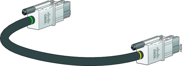
Figure 2-4 XPS 2200 Cables (for use with Catalyst 3750-X and Catalyst 3560-X Switches)

Connecting the Cables
|
Warning |
Follow these steps to connect the cables:
Step 1 ![]() Connect one end of the XPS cable to an XPS power port (Figure 2-5).
Connect one end of the XPS cable to an XPS power port (Figure 2-5).
Figure 2-5 Connecting the Cable to the XPS Power Port

Step 2 ![]() Connect the other end of the XPS cable to the XPS port on the switch (Figure 2-6).
Connect the other end of the XPS cable to the XPS port on the switch (Figure 2-6).
Figure 2-6 Connecting the Cable to the Switch

Step 3 ![]() Using a ratcheting torque screwdriver, torque each screw to 5 in-lbf. (80 ozf-in.).
Using a ratcheting torque screwdriver, torque each screw to 5 in-lbf. (80 ozf-in.).
To ensure proper operation, be sure that you completely seat the connector and that you securely tighten the screws.
Step 4 ![]() Repeat Step 1 through Step 3 for each switch that the XPS supports. Figure 2-7 shows a nine-switch stack connected to the XPS.
Repeat Step 1 through Step 3 for each switch that the XPS supports. Figure 2-7 shows a nine-switch stack connected to the XPS.
Figure 2-7 StackPower Star Topology Using the XPS

Step 5 ![]() The LEDs for the connected devices should be green. If the LEDs for the connected devices are not green, see Chapter 4 "Troubleshooting."
The LEDs for the connected devices should be green. If the LEDs for the connected devices are not green, see Chapter 4 "Troubleshooting."
|
Note |
 Feedback