Installation
Power On and Initial Setup
Ensure that the BE6000 server has been rack mounted, connected to a power supply, connected to the data network, and a monitor and keyboard is connected to the server, as described in the Quick Start Guide.


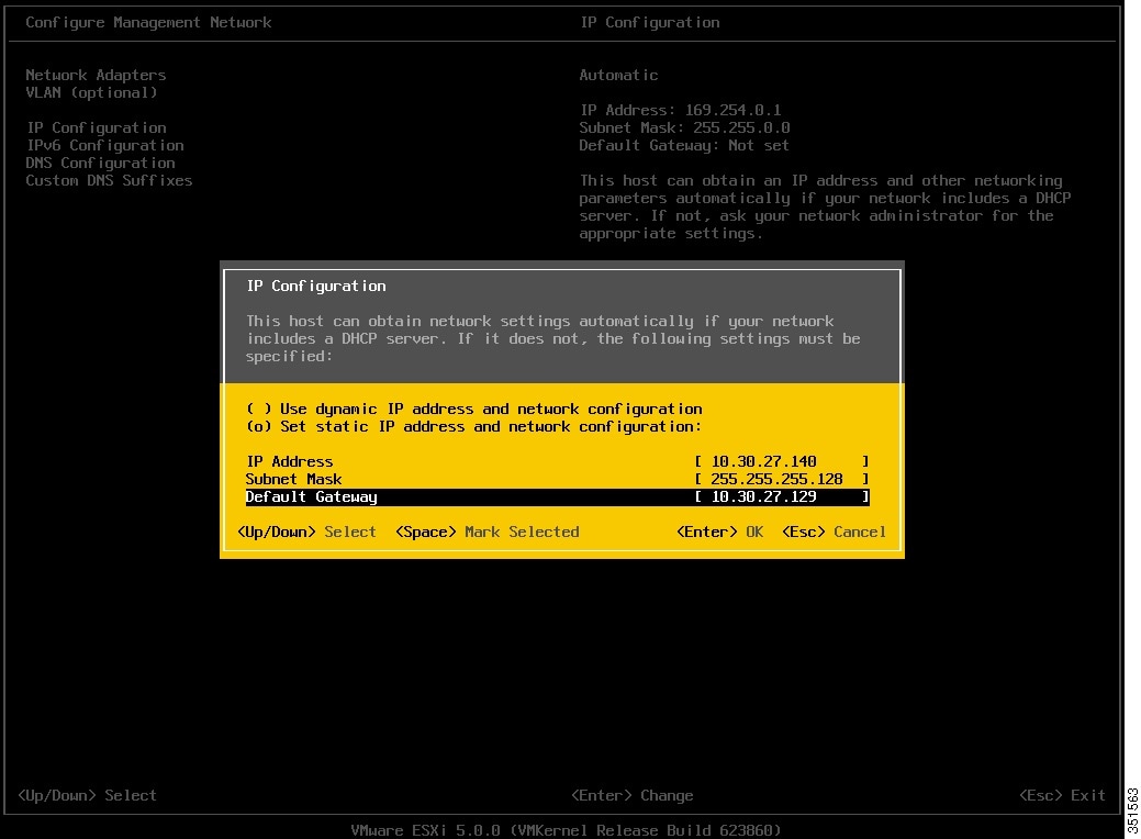
Customize ESXi Host for Remote Access
Follow this procedure to customize the ESXi host (the VMware hypervisor) to enable remote access from your PC using the vSphere client.

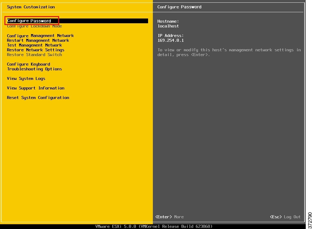
Access and Configure ESXi Host
Some Business Edition applications require the services of a valid NTP server. Follow these steps to access the ESXi host, configure NTP, configure fault tolerance for network interface cards (NICs) using the NIC teaming feature, view preinstalled applications, and browse the datastore to verify the preloaded collaboration application software.
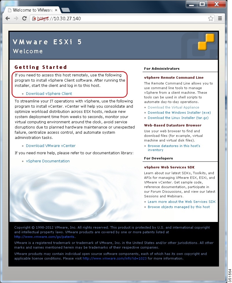
| Step 1 | Launch the
vSphere client application and type the IP address of the ESXi host.
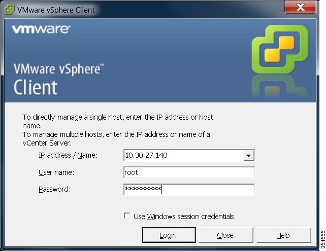 | ||||
| Step 2 | Use the login credentials that you previously configured during ESXi system customization. | ||||
| Step 3 | (optional) The VMware license is not preinstalled, and you
may be presented with a 60 day evaluation license warning. You may also receive this warning if you performed a factory reset to the UCS server. In these cases,
follow these steps to apply the license. You may also verify the license status
using these steps:
 | ||||
| Step 4 | Add the NTP
server:
| ||||
| Step 5 | Configure
fault tolerance by using the NIC teaming feature in VMware:
 The ESXi host is now ready for deploying virtual machines, which will host individual collaboration applications. Software for these applications are preloaded on the datastore of the Business Edition server. | ||||
| Step 6 | Browse the
datastore:
 | ||||
| Step 7 | (Optional) Cisco recommends that you archive the OVA-ISO directory because, in the case of merchandise returned for troubleshooting, the new UCS server may have a blank datastore. |
What to Do Next
Install virtual machines.
Preloaded Files on Datastore
Cisco Business Edition servers are shipped with selected Collaboration software, license files that are preloaded on the datastore. Consider the following points for a basic understanding of the preloaded file types:
- ISO
-
An ISO file is a DVD image containing application install files.
- OVA
-
Open Virtualization Archive (OVA) is used to package and distribute the virtual machine.
Some OVA files may include a prepared disk that includes preinstalled software (for example, cpc-provisioning-9.5.0-245-small.ova ).
Some OVA files do not have application software preinstalled. In this case, you must install the software using the ISO file that is provided on datastore (for example, cucm_9.1_vmv8_v1.7.ova and associated ISO file Bootable_UCSInstall_UCOS_9.1.2.10000-28.sgn.iso) .
 Note | For preloaded files in the Export Restricted or Export Unrestricted software, see the relevant Release Note. |
Deploy Virtual Machines
Follow this procedure to deploy virtual machines for applications that are listed in the preloaded files. For preloaded files in the Export Restricted or Export Unrestricted software, see the relevant Release Note here: http://www.cisco.com/c/en/us/support/unified-communications/business-edition-6000/products-release-notes-list.html.
The OVA template file defines the virtual machine for specific applications.
- OVAs are deployed in seconds, and a preinstalled OVA may take 10-15 minutes to deploy.
- The figure below shows the view of vSphere client after deployment of various collaboration applications virtual machines. You can also see the time that is taken to deploy the last two virtual machines.
-
Figure 11. Deployed Virtual Machines for Applications Viewed in VSphere Client. The example in the figure below is for the High Density (HD) server model, which can host four collaboration applications plus Prime Collaboration Provisioning. The Medium Density (MD) server model of a Business Edition server can also host four collaboration applications plus Prime Collaboration Provisioning.
Note
In Release 10.5(1) and later, five applications are preinstalled. If you are deploying virtual machines using any of these five applications, you can skip the following procedure.
| Step 1 | On the vSphere
Client, navigate to
.
The Deploy OVF Template screen is launched. |
| Step 2 | Browse and select the source OVA template file on your PC. For application and filename mapping, see the Release Note pertaining to Export Restricted software here: http://www.cisco.com/c/en/us/support/unified-communications/business-edition-6000/products-release-notes-list.html. |
| Step 3 | Continue to click Next to accept license agreements and default values. |
| Step 4 | Configure your deployment: |
| Step 5 | Specify a meaningful name for the VM. |
What to Do Next
After deploying all required virtual machines, install individual collaboration applications.
Install Applications on Virtual Machines
Follow this procedure to install and set up the applications on their designated virtual machines.
The approximate time that is required for each application is as follows:
- Cisco Unified Communications Manager: 60 minutes
- Cisco Unity Connection: 60 minutes
- Cisco Unified Communications Manager IM and Presence Service: 45 minutes
- Cisco Prime Collaboration: 30 minutes
- Cisco Unified Contact Center Express: 60 minutes
- Cisco Emergency Responder: 45 minutes
- Video Communication Server: 60 minutes
- Cisco Paging Server: 15 minutes
Note |
|
| Step 1 | Contact the data network administrator and make sure that you collect the network information that is described in "Preparation." | ||
| Step 2 | Plan the sequence of installing the applications to minimize the time that is required. | ||
| Step 3 | Using vSphere
client, select an application’s virtual machine. The client changes the panel
name to application name, and adds one more tab named
"Getting
Started". Right click to open the action
menu as shown in the figure below.
 | ||
| Step 4 | For VMs that
are deployed using blank OVA templates, you need to edit the settings of
virtual machines to connect the ISO image of application software at power on.
Note that Unified Communications Manager and Cisco Unity Connection use same
ISO file (see the Preloaded files for Cisco Business Edition 6000 here:
http://www.cisco.com/c/en/us/support/unified-communications/business-edition-6000/products-release-notes-list.html).
 | ||
| Step 5 | Select Edit Settings from the right-click menu as shown in Figure 12. The Virtual Machines Properties editing screen appears, as shown in the Figure 13. | ||
| Step 6 | To begin
installation of each application, follow these steps: Installation will
continue automatically for the time listed in Step 2.
|

What to Do Next
After installing all required applications, access applications using a web browser and perform initial setup of some applications.
Examples of Application Installation
The following are steps to install Cisco Unified Communications Manager (a blank OVA) and Cisco Video Communications Server (a preinstalled OVA).
Note | If the application is preinstalled and the FLP file is copied in the Answer File Generator directory, as described in previous section, installation will happen automatically without installer intervention |
Install Cisco Unified Communications Manager
| Step 1 | Power on and open the console of the virtual machine, as illustrated in Figure 12. | ||
| Step 2 | On the DVD Found window, select No for media check. | ||
| Step 3 | In the Product Deployment Selection window, select Cisco Unified Communications Manager, then select OK. Finally, select Yes in the next Proceed with Install window.
| ||
| Step 4 | Perform the following steps: | ||
| Step 5 | Select No for DHCP. The Static Network Configuration window appears. | ||
| Step 6 | Enter the hostname, (such as CUCM), IP address, IP mask, and gateway address; then select OK. Select Yes for DNS Client, followed by entering DNS server information in next window. | ||
| Step 7 | The next two windows prompt you to set up administrative login information and organization information, followed by confirming whether the server is the first node; in most cases, select Yes. | ||
| Step 8 | In the next windows, select No for network connectivity test, and again provide the hostname, IP address and security password. Finally, provide a valid reachable NTP server. | ||
| Step 9 | The next two windows prompt you to set a security password and SMTP server information. Finally, application user information is required, followed by the last window Platform Configuration Confirmation. Select OK to continue the installation, which will last for approximately 60 minutes without any user interaction on the console. After you see the login prompt on the console, access the Unified Communications Manager IP address in a web browser. |
Install Cisco Video Communications Server
| Step 1 | Power on and open the console of the virtual machine, as illustrated in Figure 12. |
| Step 2 | At the login prompt, enter admin for username and TANDBERG for the password. |
| Step 3 | At the Run Install Wizard prompt, type Y and press Enter. |
| Step 4 | To change password, type Y and press Enter, and at the prompt type the new password and click Enter. |
| Step 5 | The next series of prompts are for network information. Select the IP Protocol (the default is IPv4), provide the IP address, subnet mask, and default gateway address. Finally, select the ethernet speed of the LAN (the default is auto). |
| Step 6 | For the Run SSH (Secure shell) daemon, type Y and press Enter. |
| Step 7 | At the Restart Now prompt, type Y and press Enter. |
| Step 8 | After the system reboots, access the Cisco Video Communication Server in a web browser. |
 Feedback