Overview
This guide provides phone operating instructions and feature descriptions for the Cisco IP Phone model 6901 and 6911.
- Physical Description of Cisco Unified IP Phone 6901
- Physical Description of Cisco Unified IP Phone 6911
Physical Description of Cisco Unified IP Phone 6901

Name |
Description |
|
| 1 | Handset with indicator light |
Functions as traditional handset and indicates an incoming call (flashing red) or new voice message (steady red). |
| 2 | Hold button  |
Places the call on hold. |
| 3 | Redial button  |
Dials the last dialed number. |
| 4 | Line button  |
Allows you to pick up a second incoming call. The Line button LED indicates the call status, allows you to answer a ringing call and swap between two calls on the same line. You can also can use the line button to create a new call when the phone is idle. The LED associated with the line button lights up to reflect the line status. Color LEDs indicate the line state: |
| 5 | Volume button |
Controls the handset and the ringer volume (on-hook). |
| 6 | Keypad |
Allows you to dial phone numbers. |
| 7 | Handset |
Phone handset. |
Phone Connections
For your phone to work, it must be connected to the corporate IP telephony network. Your system administrator can help you connect your phone.

| 1 | Slot for Ethernet cable | 4 | Network port (10/100 SW) connection. IEEE 802.3af power enabled. |
| 2 | Handset connection | 5 | DC adaptor port (DC48V) |
| 3 | Slot for handset cable | 6 | Slot for DC adaptor cable |
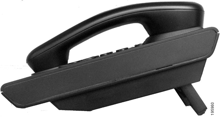
Footstand
The Cisco Unified IP Phone 6901 and 6961 has a foldable footstand. When the footstand is unfolded, it gives the phone an elevated viewing angle.
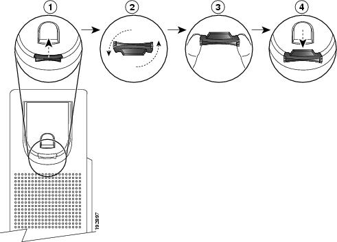
Adjusting the Handset Rest
You can adjust the handset rest of a wall-mounted phone so that the receiver does not slip out of the cradle.
Hookswitch
The hookswitch button is located on the cradle rest of your phone. You can press and quickly release the hookswitch button to activate features (hookflash) on your phone.
Physical Description of Cisco Unified IP Phone 6911
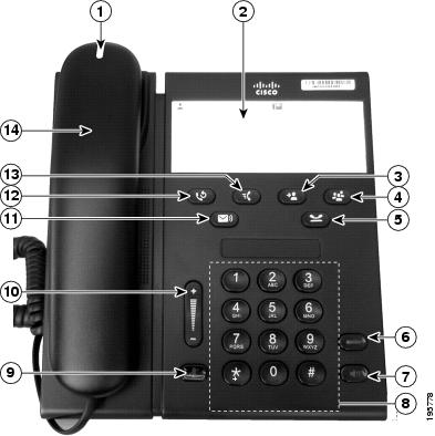
| Name | Description | |
1 |
Handset with light strip |
Lights up to indicate a ringing call (flashing red) or a new voice message (steady red). |
2 |
Paper label |
A paper strip used to enter name and contact numbers. |
3 |
Transfer button  |
Transfers active calls to another extension. |
4 |
Conference button  |
Initiates the conference call. |
5 |
Hold button |
Places an active call on hold. |
6 |
Line button  |
Allows users to pick up a second incoming call and to resume a help call. The LED shows call status. |
7 |
Speakerphone button  |
Selects the speakerphone as the default audio path and initiates a new call, picks up an incoming call, or ends a call. During a call, the button is lit green. The speakerphone audio path does not change until a new default audio path is selected (for example, by picking up the handset). |
8 |
Keypad |
Allows you to dial phone numbers. |
9 |
Mute button  |
Toggles the microphone on or off. When the microphone is muted, the button is lit red. |
10 |
Volume button  |
Controls the handset and speakerphone volume (off-hook) and the ringer volume (on-hook). |
11 |
Messages button  |
Auto-dials your voice messaging system (varies by system). |
12 |
Redial button |
Dials the last dialed number. |
13 |
Feature button  |
Depending on how your system administrator sets up the phone, the feature button provides you access to several features like Speed dialing, Call Forward All, Call Park, Pickup, Group Pickup and MeetMe Conference. Users can configure up to nine items on the feature button. To access these features, press the feature button followed by the number associated with the feature. You must press the feature button and the number within five seconds of each other. The number can only be a single digit number from 1–9. |
- Paper Label
- Phone Connections
- Footstand
- Higher Viewing Angle
- Lower Viewing Angle
- Adjusting the Handset Rest
Paper Label
The Cisco Unified IP Phone 6911 does not include an LCD display. A paper strip is provided and can be used to enter name and contact numbers.
Phone Connections
For your phone to work, it must be connected to the corporate IP telephony network. Your system administrator can help you connect your phone.
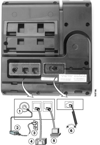
| 1 | DC adaptor port (DC48V) | 4 | Network port (10/100 SW) connection. IEEE 802.3af power enabled. |
| 2 | AC-to-DC power supply (optional) | 5 | Access port (10/100 PC) connection |
| 3 | AC power wall plug (optional) | 6 | Handset connection |
Footstand
If your phone is placed on a table or desk, the footstand can be connected to the back of the phone for a higher or lower viewing angle, depending on your preference.
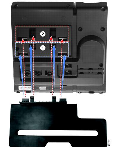
| 1 | Footstand slots for a higher viewing angle | 2 | Footstand slots for a lower viewing angle |
Higher Viewing Angle

Lower Viewing Angle

Adjusting the Handset Rest
You can adjust the handset rest of a wall-mounted phone so that the receiver does not slip out of the cradle.
 Feedback