- Preface
- Chapter 1 - Overview
- Chapter 2 - Using the Web-Browser and CLI Interfaces
- Chapter 3 - Configuring Ports and Interfaces
- Chapter 4 - Configuring Controller Settings
- Chapter 5 - Configuring Security Solutions
- Chapter 6 - Configuring WLANs
- Chapter 7 - Controlling Lightweight Access Points
- Chapter 8 - Controlling Mesh Access Points
- Chapter 9 - Managing Controller Software and Configurations
- Chapter 10 - Managing User Accounts
- Chapter 11 - Configuring Radio Resource Management
- Chapter 12 - Configuring Mobility Groups
- Chapter 13 - Configuring Hybrid REAP
- Appendix A - Safety Considerations and Translated Safety Warnings
- Appendix B - Declarations of Conformity and Regulatory Information
- Appendix C - End User License and Warranty
- Appendix D - Troubleshooting
- Appendix E - Logical Connectivity Diagrams
- Index
- Overview of Ports and Interfaces
- Configuring the Management, AP-Manager, Virtual, and Service-Port Interfaces
Configuring Ports and Interfaces
This chapter describes the controller’s physical ports and interfaces and provides instructions for configuring them. It contains these sections:
- Overview of Ports and Interfaces
- Configuring the Management, AP-Manager, Virtual, and Service-Port Interfaces
- Configuring Dynamic Interfaces
- Configuring Ports
- Configuring the Management, AP-Manager, Virtual, and Service-Port Interfaces
- Choosing Between Link Aggregation and Multiple AP-Manager Interfaces
- Enabling Link Aggregation
- Configuring Multiple AP-Manager Interfaces
Overview of Ports and Interfaces
Three concepts are key to understanding how controllers connect to a wireless network: ports, interfaces, and WLANs.
Ports
A port is a physical entity that is used for connections on the controller platform. Controllers have two types of ports: distribution system ports and a service port. The following figures show the ports available on each controller.

Note The controller in a Cisco Integrated Services Router and the controllers on the Cisco WiSM do not have external physical ports. They connect to the network through ports on the router or switch.
Figure 3-1 Ports on the Cisco 2100 Series Wireless LAN Controllers

Figure 3-2 Ports on the Cisco 4400 Series Wireless LAN Controllers

Note Figure 3-2 shows a Cisco 4404 controller. The Cisco 4402 controller is similar but has only two distribution system ports. The utility port, which is the unlabeled port in Figure 3-2, is currently not operational.
Figure 3 Ports on the Cisco 5500 Series Wireless LAN Controllers
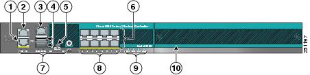
Console port (RJ-45)1 |
|||
Power supply (PS1 and PS2), System (SYS), and Alarm (ALM) LEDs |
|||
Figure 3-4 Ports on the Catalyst 3750G Integrated Wireless LAN Controller Switch

Table 3-1 provides a list of ports per controller.
Controller Network Module within the Cisco 28/37/38xx Series Integrated Services Routers |
12 |
||
Note Appendix E, Logical Connectivity Diagrams provides logical connectivity diagrams and related software commands for the integrated controllers.
Distribution System Ports
A distribution system port connects the controller to a neighbor switch and serves as the data path between these two devices.
- Cisco 2100 series controllers have eight 10/100 copper Ethernet distribution system ports through which the controller can support up to 6, 12, or 25 access points. Two of these ports (7 and 8) are power-over-Ethernet (PoE) enabled and can be used to provide power directly to access points that are connected to these ports.
Note All client connections to the 2100 series controllers are limited to the 10/100 Ethernet uplink port connection between the switch and the controller, even though their connection speeds might be higher. The exception is for access points running in local hybrid-REAP mode because this traffic is switched at the access point level and not forwarded back to the controller.
- Cisco 4402 controllers have two Gigabit Ethernet distribution system ports, each of which is capable of managing up to 48 access points. However, Cisco recommends no more than 25 access points per port due to bandwidth constraints. The 4402-25 and 4402-50 models allow a total of 25 or 50 access points to join the controller.
- Cisco 4404 controllers have four Gigabit Ethernet distribution system ports, each of which is capable of managing up to 48 access points. However, Cisco recommends no more than 25 access points per port due to bandwidth constraints. The 4404-25, 4404-50, and 4404-100 models allow a total of 25, 50, or 100 access points to join the controller.
Note The Gigabit Ethernet ports on the 4402 and 4404 controllers accept these SX/LC/T small form-factor plug-in (SFP) modules:
- 1000BASE-SX SFP modules, which provide a 1000-Mbps wired connection to a network through an 850nM (SX) fiber-optic link using an LC physical connector
- 1000BASE-LX SFP modules, which provide a 1000-Mbps wired connection to a network through a 1300nM (LX/LH) fiber-optic link using an LC physical connector
- 1000BASE-T SFP modules, which provide a 1000-Mbps wired connection to a network through a copper link using an RJ-45 physical connector
- Cisco 5508 controllers have eight Gigabit Ethernet distribution system ports, through which the controller can manage multiple access points. The 5508-12, 5508-25, 5508-50, 5508-100, and 5508-250 models allow a total of 12, 25, 50, 100, or 250 access points to join the controller. Cisco 5508 controllers have no restrictions on the number of access points per port. However, Cisco recommends using link aggregation (LAG) or configuring dynamic AP-manager interfaces on each Gigabit Ethernet port to automatically balance the load. If more than 100 access points are connected to the 5500 series controller, make sure that more than one gigabit Ethernet interface is connected to the upstream switch.
Note The Gigabit Ethernet ports on the 5508 controllers accept these SX/LC/T small form-factor plug-in (SFP) modules:
- 1000BASE-SX SFP modules, which provide a 1000-Mbps wired connection to a network through an 850nM (SX) fiber-optic link using an LC physical connector
- 1000BASE-LX SFP modules, which provide a 1000-Mbps wired connection to a network through a 1300nM (LX/LH) fiber-optic link using an LC physical connector
- 1000BASE-T SFP modules, which provide a 1000-Mbps wired connection to a network through a copper link using an RJ-45 physical connector
- The Cisco Catalyst 6500 Series Switch Wireless Services Module (WiSM) and the Cisco 7600 Series Router Wireless Services Module (WiSM) have eight internal Gigabit Ethernet distribution system ports (ports 1 through 8) that connect the switch or router and the integrated controller. These internal ports are located on the backplane of the switch or router and are not visible on the front panel. Through these ports, the controller can support up to 300 access points.
- The controller network module within the Cisco 28/37/38xx Series Integrated Services Router can support up to 6, 8, 12, or 25 access points (and up to 256, 256, 350, or 350 clients, respectively), depending on the version of the network module. The network module supports these access points through a Fast Ethernet distribution system port (on the NM-AIR-WLC6-K9 6-access-point version) or a Gigabit Ethernet distribution system port (on the 8-, 12-, and 25-access-point versions and on the NME-AIR-WLC6-K9 6-access-point version) that connects the router and the integrated controller. This port is located on the router backplane and is not visible on the front panel. The Fast Ethernet port operates at speeds up to 100 Mbps, and the Gigabit Ethernet port operates at speeds up to 1 Gbps.
- The Catalyst 3750G Integrated Wireless LAN Controller Switch has two internal Gigabit Ethernet distribution system ports (ports 27 and 28) that connect the switch and the integrated controller. These internal ports are located on the switch backplane and are not visible on the front panel. Each port is capable of managing up to 48 access points. However, Cisco recommends no more than 25 access points per port due to bandwidth constraints. The -S25 and -S50 models allow a total of 25 or 50 access points to join the controller.
Note Refer to the “Choosing Between Link Aggregation and Multiple AP-Manager Interfaces” section if you want to configure your Cisco 4400 series controller to support more than 48 access points.
Each distribution system port is, by default, an 802.1Q VLAN trunk port. The VLAN trunking characteristics of the port are not configurable.
Note Some controllers support link aggregation (LAG), which bundles all of the controller’s distribution system ports into a single 802.3ad port channel. Cisco 4400 series controllers support LAG in software release 3.2 or later, Cisco 5500 series controllers support LAG in software release 6.0 or later, and LAG is enabled automatically on the controllers within the Cisco WiSM and the Catalyst 3750G Integrated Wireless LAN Controller Switch. Refer to the “Enabling Link Aggregation” section for more information.
Service Port
Cisco 4400 and 5500 series controllers also have a 10/100 copper Ethernet service port. The service port is controlled by the service-port interface and is reserved for out-of-band management of the controller and system recovery and maintenance in the event of a network failure. It is also the only port that is active when the controller is in boot mode. The service port is not capable of carrying 802.1Q tags, so it must be connected to an access port on the neighbor switch. Use of the service port is optional.
Note The Cisco WiSM’s controllers use the service port for internal protocol communication between the controllers and the Supervisor 720.
Note The Cisco 2100 series controllers and the controller in the Cisco Integrated Services Router do not have a service port.
Note The service port is not auto-sensing. You must use the correct straight-through or crossover Ethernet cable to communicate with the service port.

Interfaces
An interface is a logical entity on the controller. An interface has multiple parameters associated with it, including an IP address, default-gateway (for the IP subnet), primary physical port, secondary physical port, VLAN identifier, and DHCP server.
These five types of interfaces are available on the controller. Four of these are static and are configured at setup time:
- Management interface (Static and configured at setup time; mandatory)
- AP-manager interface (Static and configured at setup time; mandatory)
Note You are not required to configure an AP-manager interface on 5500 series controllers.
- Virtual interface (Static and configured at setup time; mandatory)
- Service-port interface (Static and configured at setup time; optional)
- Dynamic interface (User-defined)
Each interface is mapped to at least one primary port, and some interfaces (management and dynamic) can be mapped to an optional secondary (or backup) port. If the primary port for an interface fails, the interface automatically moves to the backup port. In addition, multiple interfaces can be mapped to a single controller port.
Note For 5500 series controllers in a non-link-aggregation (non-LAG) configuration, the management interface must be on a different VLAN than any dynamic AP-manager interface. Otherwise, the management interface cannot fail over to the port that the AP-manager is on.
Note Cisco 5500 series controllers do not support fragmented pings on any interface. Similarly, Cisco 4400 series controllers, the Cisco WiSM, and the Catalyst 3750G Integrated Wireless LAN Controller Switch do not support fragmented pings on the AP-manager interface.
Note Refer to the “Enabling Link Aggregation” section if you want to configure the controller to dynamically map the interfaces to a single port channel rather than having to configure primary and secondary ports for each interface.
Management Interface
The management interface is the default interface for in-band management of the controller and connectivity to enterprise services such as AAA servers. It is also used for communications between the controller and access points. The management interface has the only consistently “pingable” in-band interface IP address on the controller. You can access the controller’s GUI by entering the controller’s management interface IP address in Internet Explorer’s or Mozilla Firefox’s Address field.
For CAPWAP, the controller requires one management interface to control all inter-controller communications and one AP-manager interface to control all controller-to-access point communications, regardless of the number of ports.
Note If the service port is in use, the management interface must be on a different supernet from the service-port interface.
Note Do not map a guest WLAN to the management interface. This is because if the EoIP tunnel breaks, the client could obtain an IP and be placed on the management subnet.
AP-Manager Interface
A controller has one or more AP-manager interfaces, which are used for all Layer 3 communications between the controller and lightweight access points after the access points have joined the controller. The AP-manager IP address is used as the tunnel source for CAPWAP packets from the controller to the access point and as the destination for CAPWAP packets from the access point to the controller.
Note For 5500 series controllers, you are not required to configure an AP-manager interface. The management interface acts like an AP-manager interface by default, and the access points can join on this interface.
The AP-manager interface communicates through any distribution system port by listening across the Layer 3 network for access point CAPWAP or LWAPP join messages to associate and communicate with as many lightweight access points as possible.
For 4404 and WiSM controllers, configure the AP-manager interface on all distribution system ports (1, 2, 3, and 4). For 4402 controllers, configure the AP-manager interface on distribution system ports 1 and 2. In both cases, the static (or permanent) AP-manager interface is always assigned to distribution system port 1 and given a unique IP address. Configuring the AP-manager interface on the same VLAN or IP subnet as the management interface results in optimum access point association, but this is not a requirement.
Note If only one distribution system port can be used, you should use distribution system port 1.
If link aggregation (LAG) is enabled, there can be only one AP-manager interface. But when LAG is disabled, one or more AP-manager interfaces can be created, generally one per physical port.
Note The 2100 series controllers do not support LAG.
Note Port redundancy for the AP-manager interface is not supported. You cannot map the AP-manager interface to a backup port.
Note Refer to the “Configuring Multiple AP-Manager Interfaces” section for information on creating and using multiple AP-manager interfaces.
Virtual Interface
The virtual interface is used to support mobility management, Dynamic Host Configuration Protocol (DHCP) relay, and embedded Layer 3 security such as guest web authentication and VPN termination. It also maintains the DNS gateway host name used by Layer 3 security and mobility managers to verify the source of certificates when Layer 3 web authorization is enabled.
Specifically, the virtual interface plays these two primary roles:
- Acts as the DHCP server placeholder for wireless clients that obtain their IP address from a DHCP server.
- Serves as the redirect address for the web authentication login page.
Note See the Configuring Security Solutions chapter for additional information on web authentication.
The virtual interface IP address is used only in communications between the controller and wireless clients. It never appears as the source or destination address of a packet that goes out a distribution system port and onto the switched network. For the system to operate correctly, the virtual interface IP address must be set (it cannot be 0.0.0.0), and no other device on the network can have the same address as the virtual interface. Therefore, the virtual interface must be configured with an unassigned and unused gateway IP address. The virtual interface IP address is not pingable and should not exist in any routing table in your network. In addition, the virtual interface cannot be mapped to a backup port.
Note All controllers within a mobility group must be configured with the same virtual interface IP address. Otherwise, inter-controller roaming may appear to work, but the hand-off does not complete, and the client loses connectivity for a period of time.
Service-Port Interface
The service-port interface controls communications through and is statically mapped by the system to the service port. The service port can obtain an IP address using DHCP, or it can be assigned a static IP address, but a default gateway cannot be assigned to the service-port interface. Static routes can be defined through the controller for remote network access to the service port.
Note Only Cisco 4400 and 5500 series controllers have a service-port interface.
Note You must configure an IP address on the service-port interface of both Cisco WiSM controllers. Otherwise, the neighbor switch is unable to check the status of each controller.
Dynamic Interface
Dynamic interfaces, also known as VLAN interfaces, are created by users and designed to be analogous to VLANs for wireless LAN clients. A controller can support up to 512 dynamic interfaces (VLANs). Each dynamic interface is individually configured and allows separate communication streams to exist on any or all of a controller’s distribution system ports. Each dynamic interface controls VLAN and other communications between controllers and all other network devices, and each acts as a DHCP relay for wireless clients associated to WLANs mapped to the interface. You can assign dynamic interfaces to distribution system ports, WLANs, the Layer 2 management interface, and the Layer 3 AP-manager interface, and you can map the dynamic interface to a backup port.
You can configure zero, one, or multiple dynamic interfaces on a distribution system port. However, all dynamic interfaces must be on a different VLAN or IP subnet from all other interfaces configured on the port. If the port is untagged, all dynamic interfaces must be on a different IP subnet from any other interface configured on the port.
Note A controller’s WLAN dynamic interface and all wireless clients in the WLAN that are local to the controller must have IP addresses in the same subnet.
Note Cisco recommends using tagged VLANs for dynamic interfaces.
Dynamic AP Management
A dynamic interface is created as a WLAN interface by default. However, any dynamic interface can be configured as an AP-manager interface, with one AP-manager interface allowed per physical port. A dynamic interface with the Dynamic AP Management option enabled is used as the tunnel source for packets from the controller to the access point and as the destination for CAPWAP packets from the access point to the controller. The dynamic interfaces for AP management must have a unique IP address and are usually configured on the same subnet as the management interface.
Note If link aggregation (LAG) is enabled, there can be only one AP-manager interface.
Cisco recommends having a separate dynamic AP-manager interface per controller port. Refer to the “Configuring Multiple AP-Manager Interfaces” section for instructions on configuring multiple dynamic AP-manager interfaces.
WLANs
A WLAN associates a service set identifier (SSID) to an interface. It is configured with security, quality of service (QoS), radio policies, and other wireless network parameters. Up to 512 access point WLANs can be configured per controller.
Note The Configuring WLANs chapter provides instructions for configuring WLANs.
Figure 3-5 illustrates the relationship between ports, interfaces, and WLANs.
Figure 3-5 Ports, Interfaces, and WLANs
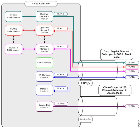
As shown in Figure 3-5, each controller port connection is an 802.1Q trunk and should be configured as such on the neighbor switch. On Cisco switches, the native VLAN of an 802.1Q trunk is an untagged VLAN. Therefore, if you configure an interface to use the native VLAN on a neighboring Cisco switch, make sure you configure the interface on the controller to be untagged.
Note A zero value for the VLAN identifier (on the Controller > Interfaces page) means that the interface is untagged.
The default (untagged) native VLAN on Cisco switches is VLAN 1. When controller interfaces are configured as tagged (meaning that the VLAN identifier is set to a non-zero value), the VLAN must be allowed on the 802.1Q trunk configuration on the neighbor switch and not be the native untagged VLAN.
Cisco recommends that tagged VLANs be used on the controller. You should also allow only relevant VLANs on the neighbor switch’s 802.1Q trunk connections to controller ports. All other VLANs should be disallowed or pruned in the switch port trunk configuration. This practice is extremely important for optimal performance of the controller.
Note Cisco recommends that you assign one set of VLANs for WLANs and a different set of VLANs for management interfaces to ensure that controllers properly route VLAN traffic.
Follow the instructions on the pages indicated to configure your controller’s interfaces and ports:
- Configuring the Management, AP-Manager, Virtual, and Service-Port Interfaces
- Configuring Dynamic Interfaces
- Configuring Ports
- Configuring the Management, AP-Manager, Virtual, and Service-Port Interfaces
- Choosing Between Link Aggregation and Multiple AP-Manager Interfaces
- Enabling Link Aggregation
- Configuring Multiple AP-Manager Interfaces
Configuring the Management, AP-Manager, Virtual, and Service-Port Interfaces
Typically, you define the management, AP-manager, virtual, and service-port interface parameters using the Startup Wizard. However, you can display and configure interface parameters through either the GUI or CLI after the controller is running.
Note When assigning a WLAN to a DHCP server, both should be on the same subnet. Otherwise, you need to use a router to route traffic between the WLAN and the DHCP server.
Using the GUI to Configure the Management, AP-Manager, Virtual, and Service-Port Interfaces
Follow these steps to display and configure the management, AP-manager, virtual, and service-port interface parameters using the GUI.
Step 1 Choose Controller > Interfaces to open the Interfaces page (see Figure 3-6).

This page shows the current controller interface settings.
Step 2 If you want to modify the settings of a particular interface, click the name of the interface. The Interfaces > Edit page for that interface appears.
Step 3 Configure the following parameters for each interface type:
Note The management interface uses the controller’s factory-set distribution system MAC address.
Note Check the Quarantine check box if you want to configure this VLAN as unhealthy or you want to configure network access control (NAC) out-of-band integration. Doing so causes the data traffic of any client that is assigned to this VLAN to pass through the controller. See the Configuring WLANs chapter for more information about NAC out-of-band integration.
Note Check the Enable NAT Address check box and enter the external NAT IP address if you want to be able to deploy your 5500 series controller behind a router or other gateway device that is using one-to-one mapping network address translation (NAT). NAT allows a device, such as a router, to act as an agent between the Internet (public) and a local network (private). In this case, it maps the controller’s intranet IP addresses to a corresponding external address. The controller’s dynamic AP-manager interface must be configured with the external NAT IP address so that the controller can send the correct IP address in the Discovery Response.
Note The NAT parameters are supported for use only with one-to-one-mapping NAT, whereby each private client has a direct and fixed mapping to a global address. They do not support one-to-many NAT, which uses source port mapping to enable a group of clients to be represented by a single IP address.
Note Enter 0 for an untagged VLAN or a non-zero value for a tagged VLAN. Cisco recommends using tagged VLANs for the management interface.
- Fixed IP address, IP netmask, and default gateway
- Dynamic AP management (for 5500 series controllers only)
Note For 5500 series controllers, the management interface acts like an AP-manager interface by default. If desired, you can disable the management interface as an AP-manager interface and create another dynamic interface as an AP manager.
- Physical port assignment (for all controllers except the 5500 series)
- Primary and secondary DHCP servers
- Access control list (ACL) setting, if required
Note To create ACLs, follow the instructions in the Configuring Security Solutions chapter.
Note For 5500 series controllers, you are not required to configure an AP-manager interface. The management interface acts like an AP-manager interface by default.
Note Enter 0 for an untagged VLAN or a non-zero value for a tagged VLAN. Cisco recommends using tagged VLANs for the AP-manager interface.
Note The AP-manager interface’s IP address must be different from the management interface’s IP address and may or may not be on the same subnet as the management interface. However, Cisco recommends that both interfaces be on the same subnet for optimum access point association.
Note To create ACLs, follow the instructions in the Configuring Security Solutions chapter.
Note To ensure connectivity and web authentication, the DNS server should always point to the virtual interface. If a DNS host name is configured for the virtual interface, then the same DNS host name must be configured on the DNS server(s) used by the client.
Note The service-port interface uses the controller’s factory-set service-port MAC address.
Step 4 Click Save Configuration to save your changes.
Step 5 If you made any changes to the management or virtual interface, reboot the controller so that your changes take effect.
Using the CLI to Configure the Management, AP-Manager, Virtual, and Service-Port Interfaces
This section provides instructions for displaying and configuring the management, AP-manager, virtual, and service-port interfaces using the CLI.
Using the CLI to Configure the Management Interface
Follow these steps to display and configure the management interface parameters using the CLI.
Step 1 Enter show interface detailed management to view the current management interface settings.
Note The management interface uses the controller’s factory-set distribution system MAC address.
Step 2 Enter config wlan disable wlan-number to disable each WLAN that uses the management interface for distribution system communication.
Step 3 Enter these commands to define the management interface:
- config interface address management ip-addr ip-netmask gateway
- config interface quarantine vlan management vlan_id
Note Use this command to configure a quarantine VLAN on the management interface.
Note Enter 0 for an untagged VLAN or a non-zero value for a tagged VLAN. Cisco recommends using tagged VLANs for the management interface.
Note Use this command to enable or disable dynamic AP management for the management interface. For 5500 series controllers, the management interface acts like an AP-manager interface by default. If desired, you can disable the management interface as an AP-manager interface and create another dynamic interface as an AP manager.
- config interface port management physical-ds-port-number (for all controllers except the 5500 series)
- config interface dhcp management ip-address-of-primary-dhcp-server [ip-address-of-secondary-dhcp-server]
- config interface acl management access-control-list-name
Note See the Configuring Security Solutions chapter for more information on ACLs.
Step 4 Enter these commands if you want to be able to deploy your 5500 series controller behind a router or other gateway device that is using one-to-one mapping network address translation (NAT):
- config interface nat-address management { enable | disable }
- config interface nat-address management set public_IP_address
NAT allows a device, such as a router, to act as an agent between the Internet (public) and a local network (private). In this case, it maps the controller’s intranet IP addresses to a corresponding external address. The controller’s dynamic AP-manager interface must be configured with the external NAT IP address so that the controller can send the correct IP address in the Discovery Response.
Note These NAT commands can be used only on 5500 series controllers and only if the management interface is configured for dynamic AP management.
Note These commands are supported for use only with one-to-one-mapping NAT, whereby each private client has a direct and fixed mapping to a global address. They do not support one-to-many NAT, which uses source port mapping to enable a group of clients to be represented by a single IP address.
Step 5 Enter save config to save your changes.
Step 6 Enter show interface detailed management to verify that your changes have been saved.
Step 7 If you made any changes to the management interface, enter reset system to reboot the controller in order for the changes to take effect.
Using the CLI to Configure the AP-Manager Interface
Follow these steps to display and configure the AP-manager interface parameters using the CLI.
Note For 5500 series controllers, you are not required to configure an AP-manager interface. The management interface acts like an AP-manager interface by default.
Step 1 Enter show interface summary to view the current interfaces.
Note If the system is operating in Layer 2 mode, the AP-manager interface is not listed.
Step 2 Enter show interface detailed ap-manager to view the current AP-manager interface settings.
Step 3 Enter config wlan disable wlan-number to disable each WLAN that uses the AP-manager interface for distribution system communication.
Step 4 Enter these commands to define the AP-manager interface:
- config interface address ap-manager ip-addr ip-netmask gateway
- config interface vlan ap-manager {vlan-id | 0}
Note Enter 0 for an untagged VLAN or a non-zero value for a tagged VLAN. Cisco recommends using tagged VLANs for the AP-manager interface.
- config interface port ap-manager physical-ds-port-number
- config interface dhcp ap-manager ip-address-of-primary-dhcp-server [ip-address-of-secondary-dhcp-server]
- config interface acl ap-manager access-control-list-name
Note See the Configuring Security Solutions chapter for more information on ACLs.
Step 5 Enter save config to save your changes.
Step 6 Enter show interface detailed ap-manager to verify that your changes have been saved.
Using the CLI to Configure the Virtual Interface
Follow these steps to display and configure the virtual interface parameters using the CLI.
Step 1 Enter show interface detailed virtual to view the current virtual interface settings.
Step 2 Enter config wlan disable wlan-number to disable each WLAN that uses the virtual interface for distribution system communication.
Step 3 Enter these commands to define the virtual interface:
Note For ip-address, enter any fictitious, unassigned, and unused gateway IP address.
Step 4 Enter reset system. At the confirmation prompt, enter Y to save your configuration changes to NVRAM. The controller reboots.
Step 5 Enter show interface detailed virtual to verify that your changes have been saved.
Using the CLI to Configure the Service-Port Interface
Follow these steps to display and configure the service-port interface parameters using the CLI.
Step 1 Enter show interface detailed service-port to view the current service-port interface settings.
Note The service-port interface uses the controller’s factory-set service-port MAC address.
Step 2 Enter these commands to define the service-port interface:
-
To configure the DHCP server: config interface dhcp service-port ip-address-of-primary-dhcp-
server [ip-address-of-secondary-dhcp-server] - To disable the DHCP server: config interface dhcp service-port none
- To configure the IP address: config interface address service-port ip-addr ip-netmask
Step 3 The service port is used for out-of-band management of the controller. If the management workstation is in a remote subnet, you may need to add a route on the controller in order to manage the controller from that remote workstation. To do so, enter this command:
config route add network-ip-addr ip-netmask gateway
Step 4 Enter save config to save your changes.
Step 5 Enter show interface detailed service-port to verify that your changes have been saved.
Configuring Dynamic Interfaces
This section provides instructions for configuring dynamic interfaces using either the GUI or CLI.
Using the GUI to Configure Dynamic Interfaces
Follow these steps to create new or edit existing dynamic interfaces using the GUI.
Step 1 Choose Controller > Interfaces to open the Interfaces page (see Figure 3-6).
Step 2 Perform one of the following:
- To create a new dynamic interface, click New. The Interfaces > New page appears (see Figure 3-7). Go to Step 3.
- To modify the settings of an existing dynamic interface, click the name of the interface. The Interfaces > Edit page for that interface appears (see Figure 3-8). Go to Step 5.
- To delete an existing dynamic interface, hover your cursor over the blue drop-down arrow for the desired interface and choose Remove.
Figure 3-7 Interfaces > New Page

Step 3 Enter an interface name and a VLAN identifier, as shown in Figure 3-7.
Step 4 Click Apply to commit your changes. The Interfaces > Edit page appears (see Figure 3-8).
Figure 3-8 Interfaces > Edit Page

Step 5 Configure the following parameters:
Note Check the Quarantine check box if you want to configure this VLAN as unhealthy or you want to configure network access control (NAC) out-of-band integration. Doing so causes the data traffic of any client that is assigned to this VLAN to pass through the controller. See the Configuring WLANs chapter for more information about NAC out-of-band integration.
- Physical port assignment (for all controllers except the 5500 series)
- NAT address (only for 5500 series controllers configured for dynamic AP management)
Note Check the Enable NAT Address check box and enter the external NAT IP address if you want to be able to deploy your 5500 series controller behind a router or other gateway device that is using one-to-one mapping network address translation (NAT). NAT allows a device, such as a router, to act as an agent between the Internet (public) and a local network (private). In this case, it maps the controller’s intranet IP addresses to a corresponding external address. The controller’s dynamic AP-manager interface must be configured with the external NAT IP address so that the controller can send the correct IP address in the Discovery Response.
Note The NAT parameters are supported for use only with one-to-one-mapping NAT, whereby each private client has a direct and fixed mapping to a global address. They do not support one-to-many NAT, which uses source port mapping to enable a group of clients to be represented by a single IP address.
Note When you enable this feature, this dynamic interface is configured as an AP-manager interface (only one AP-manager interface is allowed per physical port). A dynamic interface that is marked as an AP-manager interface cannot be used as a WLAN interface.
Note Set the APs in a VLAN that is different from the dynamic interface configured on the Controller. If the APs are in the same VLAN as the dynamic interface, the APs are not registered on the Controller and the 'LWAPP discovery rejected' and 'Layer 3 discovery request not received on management VLAN' errors are logged on the Controller.
- VLAN identifier
- Fixed IP address, IP netmask, and default gateway
- Primary and secondary DHCP servers
- Access control list (ACL) name, if required
Note See the Configuring Security Solutions chapter for more information on ACLs.
Note To ensure proper operation, you must set the Port Number and Primary DHCP Server parameters.
Step 6 Click Save Configuration to save your changes.
Step 7 Repeat this procedure for each dynamic interface that you want to create or edit.
Using the CLI to Configure Dynamic Interfaces
Follow these steps to configure dynamic interfaces using the CLI.
Step 1 Enter show interface summary to view the current dynamic interfaces.
Step 2 To view the details of a specific dynamic interface, enter show interface detailed operator_defined_interface_name.
Step 3 Enter config wlan disable wlan_id to disable each WLAN that uses the dynamic interface for distribution system communication.
Step 4 Enter these commands to configure dynamic interfaces:
- config interface create operator_defined_interface_name {vlan_id | x}
- config interface address operator_defined_interface_name ip_addr ip_netmask [gateway]
- config interface vlan operator_defined_interface_name {vlan_id | 0}
- config interface port operator_defined_interface_name physical_ds_port_number
- config interface ap-manager operator_defined_interface_name { enable | disable }
Note Use this command to enable or disable dynamic AP management. When you enable this feature, this dynamic interface is configured as an AP-manager interface (only one AP-manager interface is allowed per physical port). A dynamic interface that is marked as an AP-manager interface cannot be used as a WLAN interface.
- config interface dhcp operator_defined_interface_name ip_address_of_primary_dhcp_server [ip_address_of_secondary_dhcp_server]
- config interface quarantine vlan interface_name vlan_id
Note Use this command to configure a quarantine VLAN on any interface.
Note See the Configuring Security Solutions chapter for more information on ACLs.
Step 5 Enter these commands if you want to be able to deploy your 5500 series controller behind a router or other gateway device that is using one-to-one mapping network address translation (NAT):
- config interface nat-address dynamic-interface operator_defined_interface_name { enable | disable }
- config interface nat-address dynamic-interface operator_defined_interface_name set public_IP_address
NAT allows a device, such as a router, to act as an agent between the Internet (public) and a local network (private). In this case, it maps the controller’s intranet IP addresses to a corresponding external address. The controller’s dynamic AP-manager interface must be configured with the external NAT IP address so that the controller can send the correct IP address in the Discovery Response.
Note These NAT commands can be used only on 5500 series controllers and only if the dynamic interface is configured for dynamic AP management.
Note These commands are supported for use only with one-to-one-mapping NAT, whereby each private client has a direct and fixed mapping to a global address. They do not support one-to-many NAT, which uses source port mapping to enable a group of clients to be represented by a single IP address.
Step 6 Enter config wlan enable wlan_id to re-enable each WLAN that uses the dynamic interface for distribution system communication.
Step 7 Enter save config to save your changes.
Step 8 Enter show interface detailed operator_defined_interface_name and show interface summary to verify that your changes have been saved.
Note If desired, you can enter config interface delete operator_defined_interface_name to delete a dynamic interface.
Configuring Ports
The controller’s ports are preconfigured with factory default settings designed to make the controllers’ ports operational without additional configuration. However, you can view the status of the controller’s ports and edit their configuration parameters at any time.
Follow these steps to use the GUI to view the status of the controller’s ports and make any configuration changes if necessary.
Step 1 Choose Controller > Ports to open the Ports page (see Figure 3-9).

This page shows the current configuration for each of the controller’s ports.
Step 2 If you want to change the settings of any port, click the number for that specific port. The Port > Configure page appears (see Figure 3-10).
Note If the management and AP-manager interfaces are mapped to the same port and are members of the same VLAN, you must disable the WLAN before making a port-mapping change to either interface. If the management and AP-manager interfaces are assigned to different VLANs, you do not need to disable the WLAN.
Note The number of parameters available on the Port > Configure page depends on your controller type. For instance, 2100 series controllers and the controller in a Cisco Integrated Services Router have fewer configurable parameters than a 4400 series controller, which is shown in Figure 3-10.
Figure 3-10 Port > Configure Page

Table 3-2 interprets the current status of the port.
Step 3 Table 3-3 lists and describes the port’s configurable parameters. Follow the instructions in the table to make any desired changes.
Step 4 Click Apply to commit your changes.
Step 5 Click Save Configuration to save your changes.
Step 6 Click Back to return to the Ports page and review your changes.
Step 7 Repeat this procedure for each additional port that you want to configure.
Step 8 Go to the following sections if you want to configure the controller’s ports for these advanced features:
- Port mirroring, see below
- Spanning Tree Protocol (STP), Configuring Spanning Tree Protocol
Configuring Port Mirroring
Mirror mode enables you to duplicate to another port all of the traffic originating from or terminating at a single client device or access point. It is useful in diagnosing specific network problems. Mirror mode should be enabled only on an unused port as any connections to this port become unresponsive.
Note The 5500 series controllers, 2100 series controllers, controller network modules, and Cisco WiSM controllers do not support mirror mode. Also, a controller’s service port cannot be used as a mirrored port.
Note Port mirroring is not supported when link aggregation (LAG) is enabled on the controller.
Note Cisco recommends that you do not mirror traffic from one controller port to another as this setup could cause network problems.
Follow these steps to enable port mirroring.
Step 1 Choose Controller > Ports to open the Ports page (see Figure 3-9).
Step 2 Click the number of the unused port for which you want to enable mirror mode. The Port > Configure page appears (see Figure 3-10).
Step 3 Set the Mirror Mode parameter to Enable.
Step 4 Click Apply to commit your changes.
Step 5 Perform one of the following:
- Follow these steps if you want to choose a specific client device that will mirror its traffic to the port you selected on the controller:
Choose Wireless > Clients to open the Clients page.
- Click the MAC address of the client for which you want to enable mirror mode. The Clients > Detail page appears.
- Under Client Details, set the Mirror Mode parameter to Enable.
- Follow these steps if you want to choose an access point that will mirror its traffic to the port you selected on the controller:
Choose Wireless > Access Points > All APs to open the All APs page.
- Click the name of the access point for which you want to enable mirror mode. The All APs > Details page appears.
- Choose the Advanced tab.
- Set the Mirror Mode parameter to Enable.
Step 6 Click Save Configuration to save your changes.
Configuring Spanning Tree Protocol
Spanning Tree Protocol (STP) is a Layer 2 link management protocol that provides path redundancy while preventing loops in the network. For a Layer 2 Ethernet network to function properly, only one active path can exist between any two network devices. STP allows only one active path at a time between network devices but establishes redundant links as a backup if the initial link should fail.
The spanning-tree algorithm calculates the best loop-free path throughout a Layer 2 network. Infrastructure devices such as controllers and switches send and receive spanning-tree frames, called bridge protocol data units (BPDUs), at regular intervals. The devices do not forward these frames but use them to construct a loop-free path.
Multiple active paths among end stations cause loops in the network. If a loop exists in the network, end stations might receive duplicate messages. Infrastructure devices might also learn end-station MAC addresses on multiple Layer 2 interfaces. These conditions result in an unstable network.
STP defines a tree with a root bridge and a loop-free path from the root to all infrastructure devices in the Layer 2 network.
Note STP discussions use the term root to describe two concepts: the controller on the network that serves as a central point in the spanning tree is called the root bridge, and the port on each controller that provides the most efficient path to the root bridge is called the root port. The root bridge in the spanning tree is called the spanning-tree root.
STP forces redundant data paths into a standby (blocked) state. If a network segment in the spanning tree fails and a redundant path exists, the spanning-tree algorithm recalculates the spanning-tree topology and activates the standby path.
When two ports on a controller are part of a loop, the spanning-tree port priority and path cost settings determine which port is put in the forwarding state and which is put in the blocking state. The port priority value represents the location of a port in the network topology and how well it is located to pass traffic. The path cost value represents media speed.
The controller maintains a separate spanning-tree instance for each active VLAN configured on it. A bridge ID, consisting of the bridge priority and the controller’s MAC address, is associated with each instance. For each VLAN, the controller with the lowest controller ID becomes the spanning-tree root for that VLAN.
STP is disabled for the controller’s distribution system ports by default. The following sections provide instructions for configuring STP for your controller using either the GUI or CLI.
Note STP cannot be configured for 2100 series controllers, 5500 series controllers, and the controller in the Catalyst 3750G Integrated Wireless LAN Controller Switch.
Using the GUI to Configure Spanning Tree Protocol
Follow these steps to configure STP using the GUI.
Step 1 Choose Controller > Ports to open the Ports page (see Figure 3-9).
Step 2 Click the number of the port for which you want to configure STP. The Port > Configure page appears (see Figure 3-10). This page shows the STP status of the port and enables you to configure STP parameters.
Table 3-4 interprets the current STP status of the port.
Step 3 Table 3-5 lists and describes the port’s configurable STP parameters. Follow the instructions in the table to make any desired changes.
Step 4 Click Apply to commit your changes.
Step 5 Click Save Configuration to save your changes.
Step 6 Click Back to return to the Ports page.
Step 7 Repeat Step 2 through Step 6 for each port for which you want to enable STP.
Step 8 Choose Controller > Advanced > Spanning Tree to open the Controller Spanning Tree Configuration page (see Figure 3-11).
Figure 3-11 Controller Spanning Tree Configuration Page

This page allows you to enable or disable the spanning tree algorithm for the controller, modify its characteristics, and view the STP status. Table 3-6 interprets the current STP status for the controller.
Step 9 Table 3-7 lists and describes the controller’s configurable STP parameters. Follow the instructions in the table to make any desired changes.
Step 10 Click Apply to commit your changes.
Step 11 Click Save Configuration to save your changes.
Using the CLI to Configure Spanning Tree Protocol
Follow these steps to configure STP using the CLI.
Step 1 Enter show spanningtree port and show spanningtree switch to view the current STP status.
Step 2 If STP is enabled, you must disable it before you can change STP settings. Enter config spanningtree switch mode disable to disable STP on all ports.
Step 3 Enter one of these commands to configure the STP port administrative mode:
- config spanningtree port mode 802.1d {port-number | all}
- config spanningtree port mode fast {port-number | all}
- config spanningtree port mode off {port-number | all}
Step 4 Enter one of these commands to configure the STP port path cost on the STP ports:
- config spanningtree port pathcost 1-65535 {port-number | all}—Specifies a path cost from 1 to 65535 to the port.
- config spanningtree port mode pathcost auto {port-number | all}—Enables the STP algorithm to automatically assign the path cost. This is the default setting.
Step 5 Enter config spanningtree port priority 0-255 port-number to configure the port priority on STP ports. The default priority is 128.
Step 6 If necessary, enter config spanningtree switch bridgepriority 0-65535 to configure the controller’s STP bridge priority. The default bridge priority is 32768.
Step 7 If necessary, enter config spanningtree switch forwarddelay 4-30 to configure the controller’s STP forward delay in seconds. The default forward delay is 15 seconds.
Step 8 If necessary, enter config spanningtree switch hellotime 1-10 to configure the controller’s STP hello time in seconds. The default hello time is 2 seconds.
Step 9 If necessary, enter config spanningtree switch maxage 6-40 to configure the controller’s STP maximum age. The default maximum age is 20 seconds.
Step 10 After you configure STP settings for the ports, enter config spanningtree switch mode enable to enable STP for the controller. The controller automatically detects logical network loops, places redundant ports on standby, and builds a network with the most efficient pathways.
Step 11 Enter save config to save your settings.
Step 12 Enter show spanningtree port and show spanningtree switch to verify that your changes have been saved.
Using the Cisco 5500 Series Controller USB Console Port
The USB console port on the 5500 series controllers connects directly to the USB connector of a PC using a USB Type A-to-5-pin mini Type B cable.
Note The 4-pin mini Type B connector is easily confused with the 5-pin mini Type B connector. They are not compatible. Only the 5-pin mini Type B connector can be used.
For operation with Microsoft Windows, the Cisco Windows USB console driver must be installed on any PC connected to the console port. With this driver, you can plug and unplug the USB cable into and from the console port without affecting Windows HyperTerminal operations.
Note Only one console port can be active at a time. When a cable is plugged into the USB console port, the RJ-45 port becomes inactive. Conversely, when the USB cable is removed from the USB port, the RJ-45 port becomes active.
- Microsoft Windows 2000, XP, Vista (Cisco Windows USB console driver required)
- Apple Mac OS X 10.5.2 (no driver required)
- Linux (no driver required)
To install the Cisco Windows USB console driver, follow these steps:
Step 1 Follow these steps to download the USB_Console.inf driver file:
a. Click this URL to go to the Software Center:
http://tools.cisco.com/support/downloads/go/Redirect.x?mdfid=278875243
b. Click Wireless LAN Controllers .
c. Click Standalone Controllers .
d. Click Cisco 5500 Series Wireless LAN Controllers .
e. Click Cisco 5508 Wireless LAN Controller .
f. Choose the USB driver file.
g. Save the file to your hard drive.
Step 2 Connect the Type A connector to a USB port on your PC.
Step 3 Connect the mini Type B connector to the USB console port on the controller.
Step 4 When prompted for a driver, browse to the USB_Console.inf file on your PC. Follow the prompts to install the USB driver.
Note Some systems might also require an additional system file. You can download the Usbser.sys file from Microsoft’s website.
The USB driver is mapped to COM port 6. Some terminal emulation programs do not recognize a port higher than COM 4. If necessary, change the Cisco USB systems management console COM port to an unused port of COM 4 or lower. To do so, follow these steps:
Step 1 From your Windows desktop, right-click My Computer and choose Manage .
Step 2 From the list on the left side, choose Device Manager .
Step 3 From the device list on the right side, double-click Ports (COM & LPT) .
Step 4 Right-click Cisco USB System Management Console 0108 and choose Properties .
Step 5 Click the Port Settings tab and click the Advanced button.
Step 6 From the COM Port Number drop-down box, choose an unused COM port of 4 or lower.
Step 7 Click OK to save; then close the Advanced Settings dialog box.
Step 8 Click OK to save; then close the Communications Port Properties dialog box.
Choosing Between Link Aggregation and Multiple AP-Manager Interfaces
As noted earlier, 4400 series controllers can support up to 48 access points per port. However, you can configure your 4400 series controller to support more access points by using link aggregation (LAG) or configuring dynamic AP-managers on each Gigabit Ethernet port. Cisco 5500 series controllers have no restrictions on the number of access points per port, but Cisco recommends using LAG or multiple AP-manager interfaces on each Gigabit Ethernet port to automatically balance the load.
The following factors should help you decide which method to use if your controller is set for Layer 3 operation:
- With LAG, all of the controller ports need to connect to the same neighbor switch. If the neighbor switch goes down, the controller loses connectivity.
- With multiple AP-manager interfaces, you can connect your ports to different neighbor devices. If one of the neighbor switches goes down, the controller still has connectivity. However, using multiple AP-manager interfaces presents certain challenges (as discussed in the “Configuring Multiple AP-Manager Interfaces” section below) when port redundancy is a concern.
Follow the instructions on the page indicated for the method you want to use:
- Link aggregation, Enabling Link Aggregation
- Multiple AP-manager interfaces, Configuring Multiple AP-Manager Interfaces
Enabling Link Aggregation
Link aggregation (LAG) is a partial implementation of the 802.3ad port aggregation standard. It bundles all of the controller’s distribution system ports into a single 802.3ad port channel, thereby reducing the number of IP addresses needed to configure the ports on your controller. When LAG is enabled, the system dynamically manages port redundancy and load balances access points transparently to the user.
Note The 2100 series controllers do not support LAG.
Note You can bundle all four ports on a 4404 controller (or two on a 4402 controller) or all eight ports on a 5508 controller into a single link.
Cisco 5500 series controllers support LAG in software release 6.0 or later, Cisco 4400 series controllers support LAG in software release 3.2 or later, and LAG is enabled automatically on the controllers within the Cisco WiSM and the Catalyst 3750G Integrated Wireless LAN Controller Switch. Without LAG, each distribution system port on a 4400 series controller supports up to 48 access points. With LAG enabled, a 4402 controller’s logical port supports up to 50 access points, a 4404 controller’s logical port supports up to 100 access points, and the logical port on the Catalyst 3750G Integrated Wireless LAN Controller Switch and on each Cisco WiSM controller supports up to 150 access points.
Figure 3-12 illustrates LAG.

LAG simplifies controller configuration because you no longer need to configure primary and secondary ports for each interface. If any of the controller ports fail, traffic is automatically migrated to one of the other ports. As long as at least one controller port is functioning, the system continues to operate, access points remain connected to the network, and wireless clients continue to send and receive data.
When configuring bundled ports on the controller, you may want to consider terminating on two different modules within a modular switch such as the Catalyst 6500; however, Cisco does not recommend connecting the LAG ports of a 5500 or 4400 series controller to multiple Catalyst 6500 or 3750G switches.
Terminating on two different modules within a single Catalyst 6500 switch provides redundancy and ensures that connectivity between the switch and the controller is maintained when one module fails. Figure 3-13 illustrates this use of redundant modules. A 4402-50 controller is connected to two different Gigabit modules (slots 2 and 3) within the Catalyst 6500. The controller’s port 1 is connected to Gigabit interface 3/1, and the controller’s port 2 is connected to Gigabit interface 2/1 on the Catalyst 6500. Both switch ports are assigned to the same channel group.
When a 5500 series controller, 4404 controller, or WiSM controller module LAG port is connected to a Catalyst 3750G or a 6500 or 7600 channel group employing load balancing, note the following:
- LAG requires the Etherchannel to be configured for the “on” mode on both the controller and the Catalyst switch.
- Once the Etherchannel is configured as “on” at both ends of the link, it does not matter if the Catalyst switch is configured for either Link Aggregation Control Protocol (LACP) or Cisco proprietary Port Aggregation Protocol (PAgP) because no channel negotiation is done between the controller and the switch. Additionally, LACP and PAgP are not supported on the controller.
- The load-balancing method configured on the Catalyst switch must be a load-balancing method that terminates all IP datagram fragments on a single controller port. Not following this recommendation may result in problems with access point association.
- The recommended load-balancing method for Catalyst switches is src-dest-ip (CLI command: port-channel load-balance src_dest_ip ).
- If the recommended load-balancing method cannot be configured on the Catalyst switch, then configure the LAG connection as a single member link or disable LAG on the controller.
Figure 3-13 Link Aggregation with Catalyst 6500 Neighbor Switch

Link Aggregation Guidelines
Keep these guidelines in mind when using LAG:
- You cannot configure the controller’s ports into separate LAG groups. Only one LAG group is supported per controller. Therefore, you can connect a controller in LAG mode to only one neighbor device.
Note The two internal Gigabit ports on the controller within the Catalyst 3750G Integrated Wireless LAN Controller Switch are always assigned to the same LAG group.
- When you enable LAG or make any changes to the LAG configuration, you must immediately reboot the controller.
- When you enable LAG, you can configure only one AP-manager interface because only one logical port is needed. LAG removes the requirement for supporting multiple AP-manager interfaces.
- When you enable LAG, all dynamic AP-manager interfaces and untagged interfaces are deleted, and all WLANs are disabled and mapped to the management interface. Also, the management, static AP-manager, and VLAN-tagged dynamic interfaces are moved to the LAG port.
- Multiple untagged interfaces to the same port are not allowed.
- When you enable LAG, you cannot create interfaces with a primary port other than 29.
- When you enable LAG, all ports participate in LAG by default. Therefore, you must configure LAG for all of the connected ports in the neighbor switch.
- When you enable LAG on the Cisco WiSM, you must enable port-channeling/Ether-channeling for all of the controller’s ports on the switch.
- When you enable LAG, port mirroring is not supported.
- When you enable LAG, if any single link goes down, traffic migrates to the other links.
- When you enable LAG, only one functional physical port is needed for the controller to pass client traffic.
- When you enable LAG, access points remain connected to the switch, and data service for users continues uninterrupted.
- When you enable LAG, you eliminate the need to configure primary and secondary ports for each interface.
- When you enable LAG, the controller sends packets out on the same port on which it received them. If a CAPWAP packet from an access point enters the controller on physical port 1, the controller removes the CAPWAP wrapper, processes the packet, and forwards it to the network on physical port 1. This may not be the case if you disable LAG.
- When you disable LAG, the management, static AP-manager, and dynamic interfaces are moved to port 1.
- When you disable LAG, you must configure primary and secondary ports for all interfaces.
- When you disable LAG, you must assign an AP-manager interface to each port on the controller. Otherwise, access points are unable to join.
- Cisco 5500 and 4400 series controllers support a single static link aggregation bundle.
- LAG is typically configured using the Startup Wizard, but you can enable or disable it at any time through either the GUI or CLI.
Note LAG is enabled by default and is the only option on the WiSM controller and the controller in the Catalyst 3750G Integrated Wireless LAN Controller Switch.
Using the GUI to Enable Link Aggregation
Follow these steps to enable LAG on your controller using the GUI.
Step 1 Choose Controller > General to open the General page (see Figure 3-14).

Step 2 Set the LAG Mode on Next Reboot parameter to Enabled.
Note Choose Disabled if you want to disable LAG. LAG is disabled by default on the Cisco 5500 and 4400 series controllers but enabled by default on the Cisco WiSM and the controller in the Catalyst 3750G Integrated Wireless LAN Controller Switch.
Step 3 Click Apply to commit your changes.
Step 4 Click Save Configuration to save your changes.
Step 6 Assign the WLAN to the appropriate VLAN.
Using the CLI to Enable Link Aggregation
Follow these steps to enable LAG on your controller using the CLI.
Step 1 Enter config lag enable to enable LAG.
Note Enter config lag disable if you want to disable LAG.
Step 2 Enter save config to save your settings.
Configuring Multiple AP-Manager Interfaces
Note Only Cisco 5500 series and 4400 series standalone controllers support the use of multiple AP-manager interfaces.
When you create two or more AP-manager interfaces, each one is mapped to a different port (see Figure 3-15). The ports should be configured in sequential order such that AP-manager interface 2 is on port 2, AP-manager interface 3 is on port 3, and AP-manager interface 4 is on port 4.
Note AP-manager interfaces need not be on the same VLAN or IP subnet, and they may or may not be on the same VLAN or IP subnet as the management interface. However, Cisco recommends that you configure all AP-manager interfaces on the same VLAN or IP subnet.
Note You must assign an AP-manager interface to each port on the controller.
Before an access point joins a controller, it sends out a discovery request. From the discovery response that it receives, the access point can tell the number of AP-manager interfaces on the controller and the number of access points on each AP-manager interface. The access point generally joins the AP-manager with the least number of access points. In this way, the access point load is dynamically distributed across the multiple AP-manager interfaces.
Note Access points may not be distributed completely evenly across all of the AP-manager interfaces, but a certain level of load balancing occurs.
Figure 3-15 Two AP-Manager Interfaces

Before implementing multiple AP-manager interfaces, you should consider how they would impact your controller’s port redundancy.
1. The 4402-50 controller supports a maximum of 50 access points and has two ports. To support the maximum number of access points, you would need to create two AP-manager interfaces (see Figure 3-15) because a 4400 series controller can support only 48 access points on one port.
2. The 4404-100 controller supports up to 100 access points and has four ports. To support the maximum number of access points, you would need to create three (or more) AP-manager interfaces (see Figure 3-16). If the port of one of the AP-manager interfaces fails, the controller clears the access points’ state, and the access points must reboot to reestablish communication with the controller using the normal controller join process. The controller no longer includes the failed AP-manager interface in the CAPWAP or LWAPP discovery responses. The access points then rejoin the controller and are load-balanced among the available AP-manager interfaces.
Figure 3-16 Three AP-Manager Interfaces

Figure 3-17 illustrates the use of four AP-manager interfaces to support 100 access points on a 4400 series controller.
Figure 3-17 Four AP-Manager Interfaces

This configuration has the advantage of load-balancing all 100 access points evenly across all four AP-manager interfaces. If one of the AP-manager interfaces fails, all of the access points connected to the controller would be evenly distributed among the three available AP-manager interfaces. For example, if AP-manager interface 2 fails, the remaining AP-manager interfaces (1, 3, and 4) would each manage approximately 33 access points.
Using the GUI to Create Multiple AP-Manager Interfaces
Using the controller GUI, follow these steps to create multiple AP-manager interfaces.
Step 1 Choose Controller > Interfaces to open the Interfaces page.
Step 2 Click New. The Interfaces > New page appears (see Figure 3-19).
Figure 3-18 Interfaces > New Page
Step 3 Enter an AP-manager interface name and a VLAN identifier, as shown above.
Step 4 Click Apply to commit your changes. The Interfaces > Edit page appears (see Figure 3-19).
Figure 3-19 Interfaces > Edit Page

Step 5 Enter the appropriate interface parameters.
Note Do not define a backup port for an AP-manager interface. Port redundancy is not supported for AP-manager interfaces. If the AP-manager interface fails, all of the access points connected to the controller through that interface are evenly distributed among the other configured AP-manager interfaces.
Step 6 To make this interface an AP-manager interface, check the Enable Dynamic AP Management check box.
Note Only one AP-manager interface is allowed per physical port. A dynamic interface that is marked as an AP-manager interface cannot be used as a WLAN interface.
Step 7 Click Save Configuration to save your settings.
Step 8 Repeat this procedure for each additional AP-manager interface that you want to create.
Using the CLI to Create Multiple AP-Manager Interfaces
Using the controller CLI, follow these steps to create multiple AP-manager interfaces.
Step 1 Enter these commands to create a new interface:
- config interface create operator_defined_interface_name {vlan_id | x}
- config interface address operator_defined_interface_name ip_addr ip_netmask [gateway]
- config interface vlan operator_defined_interface_name {vlan_id | 0}
- config interface port operator_defined_interface_name physical_ds_port_number
- config interface dhcp operator_defined_interface_name ip_address_of_primary_dhcp_server [ip_address_of_secondary_dhcp_server]
- config interface quarantine vlan interface_name vlan_id
Note Use this command to configure a quarantine VLAN on any interface.
Note See the Configuring Security Solutions chapter for more information on ACLs.
Step 2 To make this interface an AP-manager interface, enter this command:
config interface ap-manager operator_defined_interface_name { enable | disable }
Note Only one AP-manager interface is allowed per physical port. A dynamic interface that is marked as an AP-manager interface cannot be used as a WLAN interface.
Step 3 To save your changes, enter this command:
Step 4 Repeat this procedure for each additional AP-manager interface that you want to create.
5500 Series Controller Example
For a 5500 series controller, Cisco recommends having eight dynamic AP-manager interfaces and associating them to the controller’s eight Gigabit ports. If you are using the management interface, which acts like an AP-manager interface by default, you need to create only 7 more dynamic AP-manager interfaces and associate them to the remaining seven Gigabit ports. For example, Figure 3-20 shows a dynamic interface that is enabled as a dynamic AP-manager interface and associated to port number 2, and Figure 3-20 shows a 5500 series controller with LAG disabled, the management interface used as one dynamic AP-manager interface, and seven additional dynamic AP-manager interfaces, each mapped to a different Gigabit port.
Figure 3-20 Dynamic Interface Example with Dynamic AP Management

Figure 3-21 5500 Series Controller Interface Configuration Example

 Feedback