- Preface
- Overview
- Using the Web-Browser and CLI Interfaces
- Ports and Interfaces
- Configuring Controller Settings
- Configuring VideoStream
- Configuring Security Solutions
- WLANs
- Controlling Lightweight Access Points
- Controlling Mesh Access Points
- Managing Controller Software and Configurations
- Managing User Accounts
- Radio Resource Management
- Configuring Cisco CleanAir
- FlexConnect
- Mobility Groups
- Configuring Mobile Concierge
- Troubleshooting
- Index
- Information About Mobility
- Information About Mobility Groups
- Mobility Groups
- Viewing Mobility Group Statistics
- Configuring Auto-Anchor Mobility
- Validating WLAN Mobility Security Values
- Using Symmetric Mobility Tunneling
- Verifying Symmetric Mobility Tunneling
- Running Mobility Ping Tests
- Configuring Dynamic Anchoring for Clients with Static IP Addresses
- Configuring Foreign Mappings
- Configuring Proxy Mobile IPv6
Mobility Groups
Information About Mobility
Mobility, or roaming, is a wireless LAN client’s ability to maintain its association seamlessly from one access point to another securely and with as little latency as possible. This section explains how mobility works when controllers are included in a wireless network.
When a wireless client associates and authenticates to an access point, the access point’s controller places an entry for that client in its client database. This entry includes the client’s MAC and IP addresses, security context and associations, quality of service (QoS) contexts, the WLAN, and the associated access point. The controller uses this information to forward frames and manage traffic to and from the wireless client.

When the wireless client moves its association from one access point to another, the controller simply updates the client database with the newly associated access point. If necessary, new security context and associations are established as well.
The process becomes more complicated, however, when a client roams from an access point joined to one controller to an access point joined to a different controller. It also varies based on whether the controllers are operating on the same subnet.

When the client associates to an access point joined to a new controller, the new controller exchanges mobility messages with the original controller, and the client database entry is moved to the new controller. New security context and associations are established if necessary, and the client database entry is updated for the new access point. This process remains transparent to the user.
 Note | All clients configured with 802.1X/Wi-Fi Protected Access (WPA) security complete a full authentication in order to comply with the IEEE standard. |

Inter-subnet roaming is similar to inter-controller roaming in that the controllers exchange mobility messages on the client roam. However, instead of moving the client database entry to the new controller, the original controller marks the client with an “Anchor” entry in its own client database. The database entry is copied to the new controller client database and marked with a “Foreign” entry in the new controller. The roam remains transparent to the wireless client, and the client maintains its original IP address.
In inter-subnet roaming, WLANs on both anchor and foreign controllers need to have the same network access privileges and no source-based routing or source-based firewalls in place. Otherwise, the clients may have network connectivity issues after the handoff.
In a static anchor setup using controllers and ACS, if AAA override is enabled to dynamically assign VLAN and QoS, the foreign controller updates the anchor controller with the right VLAN after a Layer 2 authentication (802.1x). For Layer 3 RADIUS authentication, the RADIUS requests for authentication are sent by the anchor controller.
Mobility is not supported for SSIDs with security type configured for Webauth on MAC filter failure.
If the management VLAN of one Cisco WLC is present as a dynamic VLAN on another Cisco WLC, the mobility feature is not supported.
Note | If a client roams in web authentication state, the client is considered as a new client on another controller instead of considering it as a mobile client. |
Note | New Mobility with WebAuth and MAC filter is not supported. For a client, if L2 authentication fails and it falls back to L3 authentication and then tries to roam to a different Cisco WLC, the roaming will fail. The same behavior is applicable to FlexConnect central switching and local mode as well. |
Information About Mobility Groups
A mobility group is a set of controllers, identified by the same mobility group name, that defines the realm of seamless roaming for wireless clients. By creating a mobility group, you can enable multiple controllers in a network to dynamically share information and forward data traffic when inter-controller or inter-subnet roaming occurs. Controllers in the same mobility group can share the context and state of client devices as well as their list of access points so that they do not consider each other’s access points as rogue devices. With this information, the network can support inter-controller wireless LAN roaming and controller redundancy.
Note | Controllers do not have to be of the same model to be a member of a mobility group. Mobility groups can be comprised of any combination of controller platforms. |
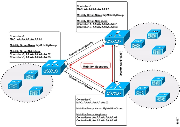
As shown above, each controller is configured with a list of the other members of the mobility group. Whenever a new client joins a controller, the controller sends out a unicast message (or multicast message if mobility multicast is configured) to all of the controllers in the mobility group. The controller to which the client was previously connected passes on the status of the client.
For example, if a controller supports 6000 access points, a mobility group that consists of 24 such controllers supports up to 144,000 access points (24 * 6000 = 144,000 access points).
Mobility groups enable you to limit roaming between different floors, buildings, or campuses in the same enterprise by assigning different mobility group names to different controllers within the same wireless network.
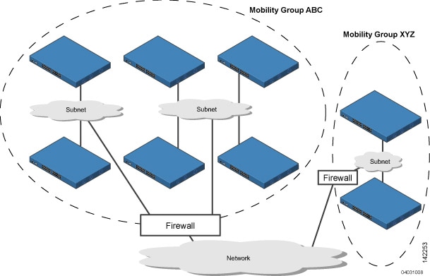
The controllers in the ABC mobility group share access point and client information with each other. The controllers in the ABC mobility group do not share the access point or client information with the XYZ controllers, which are in a different mobility group. Likewise, the controllers in the XYZ mobility group do not share access point or client information with the controllers in the ABC mobility group. This feature ensures mobility group isolation across the network.
Every controller maintains information about its peer controllers in a mobility list. Controllers can communicate across mobility groups and clients may roam between access points in different mobility groups if the controllers are included in each other’s mobility lists. In the following example, controller 1 can communicate with either controller 2 or 3, but controller 2 and controller 3 can communicate only with controller 1 and not with each other. Similarly, clients can roam between controller 1 and controller 2 or between controller 1 and controller 3 but not between controller 2 and controller 3.
| Controller 1
Mobility group: A Mobility list: Controller 1 (group A) Controller 2 (group A) Controller 3 (group C) ? |
Controller 2
Mobility group: A Mobility list: Controller 1 (group A) Controller 2 (group A) |
Controller 3
Mobility group: C Mobility list: Controller 1 (group A) Controller 3 (group C) |
The controller supports seamless roaming across multiple mobility groups. During seamless roaming, the client maintains its IP address across all mobility groups; however, Cisco Centralized Key Management (CCKM) and proactive key caching (PKC) are supported only for inter-mobility-group roaming. When a client crosses a mobility group boundary during a roam, the client is fully authenticated, but the IP address is maintained, and mobility tunneling is initiated for Layer 3 roaming.
Note | When a controller is added to a mobility group, some of the APs (which are running in local mode) do not get the complete controllers list updated, those APs are connected to controllers that are in the same mobility group. You can view the controller list in the APs using the command "show capwap client config" AP-NAME command. For example, if the mobility group is for 19 controllers and then you add two more controllers to the mobility group, the AP shows 19 controllers instead of 21 in its list. To address this issue, you can reboot the AP or move it to another controller that is part of the same mobility group to get the controller list updated. This issue is observed in AP1242 connected to different 5508 controllers running code 7.6.120.0. |
Note | When client moves to a non anchored SSID from an anchored sSSID on foreign, there is a stale entry on foreign .This happens when multicast mobile announce does not reach from foreign to guest anchor due to whatsoever reason, due to this the service is not impacted and configuration goes unnoticed but silently leaks MSCB on GA .There is no debug or error message shown nor does the GA runs a timer per client to cleanup. A HandoffEnd needs to be sent from foreign to Anchor since there is no timer. |
Messaging Among Mobility Groups
The controller provides intersubnet mobility for clients by sending mobility messages to other member controllers.
The controller sends a Mobile Announce message to members in the mobility list each time that a new client associates to it. The controller sends the message only to those members that are in the same group as the controller (the local group) and then includes all of the other members while sending retries.
You can configure the controller to use multicast to send the Mobile Announce messages. This behavior allows the controller to send only one copy of the message to the network, which destines it to the multicast group that contains all the mobility members. To derive the maximum benefit from multicast messaging, we recommend that it be enabled on all group members.
Using Mobility Groups with NAT Devices
Mobility message payloads carry IP address information about the source controller. This IP address is validated with the source IP address of the IP header. This behavior is a problem when a NAT device is introduced in the network because it changes the source IP address in the IP header. In the guest WLAN feature, any mobility packet, that is being routed through a NAT device is dropped because of the IP address mismatch.
The mobility group lookup uses the MAC address of the source controller. Because the source IP address is changed due to the mapping in the NAT device, the mobility group database is searched before a reply is sent to get the IP address of the requesting controller. This process is done using the MAC address of the requesting controller.
When configuring the mobility group in a network where NAT is enabled, enter the IP address that is sent to the controller from the NAT device rather than the controller’s management interface IP address. Also, make sure that the following ports are open on the firewall if you are using a firewall such as PIX:
Mobility Groups
Prerequisites for Configuring Mobility Groups
Before you add controllers to a mobility group, you must verify that the following requirements have been met for all controllers that are to be included in the group:
-
IP connectivity must exist between the management interfaces of all controllers.
Note
You can verify IP connectivity by pinging the controllers.
-
When controllers in the mobility list use different software versions, Layer 2 or Layer 3 clients have limited roaming support. Layer 2 or Layer 3 client roaming is supported only between controllers that use the same version or with controllers that run versions 7.X.X.
-
All controllers must be configured with the same virtual interface IP address.
Note
If necessary, you can change the virtual interface IP address by editing the virtual interface name on the Controller > Interfaces page.
-
You must have gathered the MAC address and IP address of every controller that is to be included in the mobility group. This information is necessary because you will be configuring all controllers with the MAC address and IP address of all the other mobility group members.
Note
You can find the MAC and IP addresses of the other controllers to be included in the mobility group on the Controller > Mobility Groups page of each controller’s GUI.
-
When you configure mobility groups using a third-party firewall, for example, Cisco PIX, or Cisco ASA, you must open port 16666, and IP protocol 97.
-
For intercontroller CAPWAP data and control traffic, you must open the ports 5247 and 5246.
Note | To view information on mobility support across controllers with different software versions, see the http://www.cisco.com/c/en/us/td/docs/wireless/compatibility/matrix/compatibility-matrix.html. . |
Note | You cannot perform port address translation (PAT) on the firewall. You must configure one-to-one network address translation (NAT). |
Configuring Mobility Groups (GUI)
| Step 1 | Choose
Controller > Mobility
Management > Mobility Groups to open the Static Mobility Group Members
page.
This page shows the mobility group name in the Default Mobility Group text box and lists the MAC address and IPv4/IPv6 address of each controller that is currently a member of the mobility group. The first entry is the local controller, which cannot be deleted.
| ||||||||
| Step 2 | Perform one of
the following to add controllers to a mobility group:
| ||||||||
| Step 3 | Click New to open the Mobility Group Member > New page. | ||||||||
| Step 4 | Add a controller
to the mobility group as follows:
The Mobility Group Members > Edit All page lists the MAC address, IPv4/IPv6 address, and mobility group name (optional) of all the controllers currently in the mobility group. The controllers are listed one per line with the local controller at the top of the list.
| ||||||||
| Step 5 | Add more
controllers to the mobility group as follows:
| ||||||||
| Step 6 | Choose
Mobility Management >
Multicast Messaging to open the Mobility Multicast Messaging page.
The names of all the currently configured mobility groups appear in the middle of the page. | ||||||||
| Step 7 | On the Mobility Multicast Messaging page, select the Enable Multicast Messaging check box to enable the controller to use multicast mode to send Mobile Announce messages to the mobility members. If you leave it unselected, the controller uses unicast mode to send the Mobile Announce messages. The default value is unselected. | ||||||||
| Step 8 | If you enabled
multicast messaging in the previous step, enter the multicast group IPv4
address for the local mobility group in the Local Group Multicast IPv4 Address
text box. This address is used for multicast mobility messaging.
| ||||||||
| Step 9 | Click Apply to commit your changes. | ||||||||
| Step 10 | If desired, you
can also configure the multicast group IPv4 address for non-local groups within
the mobility list. To do so, click the name of a non-local mobility group to
open the Mobility Multicast Messaging > Edit page, and enter the multicast
group IPv4 address for the non-local mobility group in the Multicast IP Address
text box.
| ||||||||
| Step 11 | Click Apply to commit your changes. | ||||||||
| Step 12 | Click Save Configuration to save your changes. |
Configuring Mobility Groups (CLI)
Viewing Mobility Group Statistics
You can view three types of mobility group statistics from the controller GUI:
Mobility initiator statistics—Generated by the controller initiating a mobility event
Mobility responder statistics—Generated by the controller responding to a mobility event
You can view mobility group statistics using the controller GUI or CLI.
Viewing Mobility Group Statistics (GUI)
| Step 1 | Choose Monitor > Statistics > Mobility Statistics to open the Mobility Statistics page. This page contains the following fields
|
| Step 2 | If you want to clear the current mobility statistics, click Clear Stats. |
Viewing Mobility Group Statistics (CLI)
Configuring Auto-Anchor Mobility
Information About Auto-Anchor Mobility
You can use auto-anchor mobility (also called guest tunneling) to improve load balancing and security for roaming clients on your wireless LANs. Under normal roaming conditions, client devices join a wireless LAN and are anchored to the first controller that they contact. If a client roams to a different subnet, the controller to which the client roamed sets up a foreign session for the client with the anchor controller. However, when you use the auto-anchor mobility feature, you can specify a controller or set of controllers as the anchor points for clients on a wireless LAN.
In auto-anchor mobility mode, a subset of a mobility group is specified as the anchor controllers for a WLAN. You can use this feature to restrict a WLAN to a single subnet, regardless of a client’s entry point into the network. Clients can then access a guest WLAN throughout an enterprise but still be restricted to a specific subnet. Auto-anchor mobility can also provide geographic load balancing because the WLANs can represent a particular section of a building (such as a lobby, a restaurant, and so on), effectively creating a set of home controllers for a WLAN. Instead of being anchored to the first controller that they happen to contact, mobile clients can be anchored to controllers that control access points in a particular vicinity.
When a client first associates to a controller of a mobility group that has been preconfigured as a mobility anchor for a WLAN, the client associates to the controller locally, and a local session is created for the client. Clients can be anchored only to preconfigured anchor controllers of the WLAN. For a given WLAN, you should configure the same set of anchor controllers on all controllers in the mobility group.
When a client first associates to a controller of a mobility group that has not been configured as a mobility anchor for a WLAN, the client associates to the controller locally, a local session is created for the client, and the client is announced to the other controllers in the mobility list. If the announcement is not answered, the controller contacts one of the anchor controllers configured for the WLAN and creates a foreign session for the client on the local switch. Packets from the client are encapsulated through a mobility tunnel using EtherIP and sent to the anchor controller, where they are decapsulated and delivered to the wired network. Packets to the client are received by the anchor controller and forwarded to the foreign controller through a mobility tunnel using EtherIP. The foreign controller decapsulates the packets and forwards them to the client.
If multiple controllers are added as mobility anchors for a particular WLAN on a foreign controller, the foreign controller internally sorts the controller by their IP address. The controller with the lowest IP address is the first anchor. For example, a typical ordered list would be 172.16.7.25, 172.16.7.28, 192.168.5.15. If the first client associates to the foreign controller's anchored WLAN, the client database entry is sent to the first anchor controller in the list, the second client is sent to the second controller in the list, and so on, until the end of the anchor list is reached. The process is repeated starting with the first anchor controller. If any of the anchor controller is detected to be down, all the clients anchored to the controller are deauthenticated, and the clients then go through the authentication/anchoring process again in a round-robin manner with the remaining controller in the anchor list. This functionality is also extended to regular mobility clients through mobility failover. This feature enables mobility group members to detect failed members and reroute clients.
Restrictions on Auto-Anchor Mobility
-
Mobility list members can send ping requests to one another to check the data and control paths among them to find failed members and reroute clients. You can configure the number and interval of ping requests that are sent to each anchor controller. This functionality provides guest N+1 redundancy for guest tunneling and mobility failover for regular mobility.
-
You must add controllers to the mobility group member list before you can designate them as mobility anchors for a WLAN.
-
You can configure multiple controllers as mobility anchors for a WLAN.
-
Auto-anchor mobility supports web authentication but does not support other Layer 3 security types.
-
You must configure the WLANs on both the foreign controller and the anchor controller with mobility anchors. On the anchor controller, configure the anchor controller itself as a mobility anchor. On the foreign controller, configure the anchor as a mobility anchor.
- It is not possible for clients, WGB, and wired clients to directly connect to a DMZ guest anchor and move to a foreign controller.
-
Auto-anchor mobility is not supported for use with DHCP option 82.
-
When using the guest N+1 redundancy and mobility failover features with a firewall, make sure that the following ports are open:
-
In case of roaming between anchor controller and foreign mobility, the client addresses learned at the anchor controller is shown at the foreign controller. You must check the foreign controller to view the RA throttle statistics.
-
For Layer 3 RADIUS authentication, the RADIUS requests for authentication are sent by the anchor controller.
-
The mobility anchor is not supported on virtual wireless LAN controllers.
-
In a guest anchor Cisco WLC deployment, ensure that the foreign Cisco WLC does not have a WLAN mapped to a VLAN that is associated with the guest anchor Cisco WLC.
Configuring Auto-Anchor Mobility (GUI)
| Step 1 | Configure the controller to
detect failed anchor controllers within a mobility group as follows:
| ||
| Step 2 | Choose WLANs to open the WLANs page. | ||
| Step 3 | Click the blue drop-down arrow for the desired WLAN or wired
guest LAN and choose
Mobility Anchors. The
Mobility Anchors page appears.
This page lists the controllers that have already been configured as mobility anchors and shows the current state of their data and control paths. Controllers within a mobility group communicate among themselves over a well-known UDP port and exchange data traffic through an Ethernet-over-IP (EoIP) tunnel. They send mpings, which test mobility control packet reachability over the management interface over mobility UDP port 16666 and they send epings, which test the mobility data traffic over the management interface over EoIP port 97. The Control Path text box shows whether mpings have passed (up) or failed (down), and the Data Path text box shows whether epings have passed (up) or failed (down). If the Data or Control Path text box shows “down,” the mobility anchor cannot be reached and is considered failed. | ||
| Step 4 | Select the IPv4/IPv6 address of the controller to be designated a mobility anchor in the Switch IP Address (Anchor) drop-down list. | ||
| Step 5 | Click
Mobility Anchor Create.
The selected controller becomes an anchor for this WLAN or wired guest LAN.
| ||
| Step 6 | Click Save Configuration. | ||
| Step 7 | Repeat Step 4 and Step 6 to set any other controllers as mobility anchors for this WLAN or wired guest LAN. | ||
| Step 8 | Configure the same set of mobility anchors on every controller in the mobility group. |
Configuring Auto-Anchor Mobility (CLI)
The controller is programmed to always detect failed mobility list members. To change the parameters for the ping exchange between mobility members, enter these commands:
config mobility group keepalive count count—Specifies the number of times a ping request is sent to a mobility list member before the member is considered to be unreachable. The valid range is 3 to 20, and the default value is 3.
config mobility group keepalive interval seconds—Specifies the amount of time (in seconds) between each ping request sent to a mobility list member. The valid range is 1 to 30 seconds, and the default value is 10 seconds.
Disable the WLAN or wired guest LAN for which you are configuring mobility anchors by entering this command:
Create a new mobility anchor for the WLAN or wired guest LAN by entering one of these commands:
config mobility group anchor add {wlan | guest-lan} {wlan_id | guest_lan_id} anchor_controller_ip_address
config {wlan | guest-lan} mobility anchor add {wlan_id | guest_lan_id} anchor_controller_ip_address
NoteThe wlan_id or guest_lan_id must exist and be disabled, and the anchor_controller_ip_address must be a member of the default mobility group.
NoteAuto-anchor mobility is enabled for the WLAN or wired guest LAN when you configure the first mobility anchor.
Delete a mobility anchor for the WLAN or wired guest LAN by entering one of these commands:
config mobility group anchor delete {wlan | guest-lan} {wlan_id | guest_lan_id} anchor_controller_ip_address
config {wlan | guest-lan} mobility anchor delete {wlan_id | guest_lan_id} anchor_controller_ip_address
NoteThe wlan_id or guest_lan_id must exist and be disabled.
NoteDeleting the last anchor disables the auto-anchor mobility feature and resumes normal mobility for new associations.
See a list and status of controllers configured as mobility anchors for a specific WLAN or wired guest LAN by entering this command:
show mobility anchor {wlan | guest-lan} {wlan_id | guest_lan_id}
NoteThe wlan_id and guest_lan_id parameters are optional and constrain the list to the anchors in a particular WLAN or guest LAN. To see all of the mobility anchors on your system, enter the show mobility anchor command.
The Status text box shows one of these values:
UP—The controller is reachable and able to pass data.
CNTRL_PATH_DOWN—The mpings failed. The controller cannot be reached through the control path and is considered failed.
DATA_PATH_DOWN—The epings failed. The controller cannot be reached and is considered failed.
CNTRL_DATA_PATH_DOWN—Both the mpings and epings failed. The controller cannot be reached and is considered failed.
See the status of all mobility group members by entering this command:
Validating WLAN Mobility Security Values
Information About WLAN Mobility Security Values
For any anchoring or mobility event, the WLAN security policy values on each controller must match. These values can be validated in the controller debugs. This table lists the WLAN mobility security values and their corresponding security policy.
|
|||
Using Symmetric Mobility Tunneling
Information About Symmetric Mobility Tunneling
When symmetric mobility tunneling is enabled, all client traffic is sent to the anchor controller and can then successfully pass the RPF check.

Symmetric mobility tunneling is also useful in the following situations:
If a firewall installation in the client packet path drops packets because the source IP address does not match the subnet on which the packets are received.
If the access-point group VLAN on the anchor controller is different than the WLAN interface VLAN on the foreign controller. In this case, client traffic could be sent on an incorrect VLAN during mobility events.
Guidelines and Limitations
Verifying Symmetric Mobility Tunneling
Verifying Symmetric Mobility Tunneling (GUI)
Verifying if Symmetric Mobility Tunneling is Enabled (CLI)
Verify that symmetric mobility tunneling is enabled by entering this command:
Running Mobility Ping Tests
Information About Mobility Ping Tests
Controllers in a mobility list communicate with each other by controlling information over a well-known UDP port and exchanging data traffic through an Ethernet-over-IP (EoIP) tunnel. Because UDP and EoIP are not reliable transport mechanisms, there is no guarantee that a mobility control packet or data packet will be delivered to a mobility peer. Mobility packets may be lost in transit due to a firewall filtering the UDP port or EoIP packets or due to routing issues.
Guidelines and Limitations
Controller software release 4.0 or later releases enable you to test the mobility communication environment by performing mobility ping tests. These tests may be used to validate connectivity between members of a mobility group (including guest controllers). Two ping tests are available:
Mobility ping over UDP—This test runs over mobility UDP port 16666. It tests whether the mobility control packet can be reached over the management interface.
Mobility ping over EoIP—This test runs over EoIP. It tests the mobility data traffic over the management interface.
Only one mobility ping test per controller can be run at a given time.
Note | These ping tests are not Internet Control Message Protocol (ICMP) based. The term “ping” is used to indicate an echo request and an echo reply message. |
Note | Any ICMP packet greater than 1280 bytes will always be responded with a packet that is truncated to 1280 bytes. For example, a ping with a packet that is greater than 1280 bytes from a host to the management interface is always responded with a packet that is truncated to 1280 bytes. |
Running Mobility Ping Tests (CLI)
To test the mobility UDP control packet communication between two controllers, enter this command:
mping mobility_peer_IP_address
The mobility_peer_IP_address parameter must be the IP address of a controller that belongs to the mobility list.
To test the mobility EoIP data packet communication between two controllers, enter this command:
eping mobility_peer_IP_address
The mobility_peer_IP_address parameter must be the IP address of a controller that belongs to the mobility list.
To troubleshoot your controller for mobility ping, enter these commands:
config logging buffered debugging
To troubleshoot your controller for mobility ping over UDP, enter this command to display the mobility control packet:
NoteWe recommend using an ethereal trace capture when troubleshooting.
Configuring Dynamic Anchoring for Clients with Static IP Addresses
Information About Dynamic Anchoring for Clients with Static IP
At times you may want to configure static IP addresses for wireless clients. When these wireless clients move about in a network, they could try associating with other controllers. If the clients try to associate with a controller that does not support the same subnet as the static IP, the clients fail to connect to the network. You can now enable dynamic tunneling of clients with static IP addresses.
Dynamic anchoring of static IP clients with static IP addresses can be associated with other controllers where the client’s subnet is supported by tunneling the traffic to another controller in the same mobility group. This feature enables you to configure your WLAN so that the network is serviced even though the clients use static IP addresses.
How Dynamic Anchoring of Static IP Clients Works
The following sequence of steps occur when a client with a static IP address tries to associate with a controller:
-
When a client associates with a controller, for example, WLC-1, it performs a mobility announcement. If a controller in the mobility group responds (for example WLC-2), the client traffic is tunneled to the controller WLC-2. As a result, the controller WLC 1 becomes the foreign controller and WLC-2 becomes the anchor controller.
-
If none of the controllers responds, the client is treated as a local client and authentication is performed. The IP address for the client is updated either through an orphan packet handling or an ARP request processing. If the IP subnet of the client is not supported in the controller (WLC-1), WLC-1 sends another static IP mobile announce and if a controller (for example WLC-3) that supports the client's subnet responds to that announcement, the client traffic is tunneled to that controller, that is WLC-3. As a result, the controller WLC 1 becomes the export foreign controller and WLC-3 becomes the export anchor controller.
-
Once the acknowledgment is received, the client traffic is tunneled between the anchor and the controller (WLC-1).
Note
If you configure WLAN with an interface group and any of the interfaces in the interface group supports the static IP client subnet, the client is assigned to that interface. This situation occurs in local or remote (static IP Anchor) controller.
When AAA override is used along with the interface group that is mapped to WLAN, the source interface that is used for DHCP transactions is the Management interface.
If the interface group that you add to a WLAN has RADIUS Server Overwrite interface enabled and a client requests for authentication, the controller selects the first IP address from the interface group as the RADIUS server.
Note
A security level 2 authentication is performed only in the local (static IP foreign) controller, which is also known as the exported foreign controller.
Restrictions on Dynamic Anchoring for Clients With Static IP Addresses
-
Do not configure overridden interfaces when you perform AAA for static IP tunneling, this is because traffic can get blocked for the client if the overridden interface does not support the client’s subnet. This can be possible in extreme cases where the overriding interface group supports the client’s subnet.
-
The local controller must be configured with the correct AAA server where this client entry is present.
The following restrictions apply when configuring static IP tunneling with other features on the same WLAN:
-
Auto anchoring mobility (guest tunneling) cannot be configured for the same WLAN.
-
FlexConnect local authentication cannot be configured for the same WLAN.
-
The DHCP required option cannot be configured for the same WLAN.
-
You cannot configure dynamic anchoring of static IP clients with FlexConnect local switching.
-
We recommend that you configure the same NTP/SNTP servers on the Cisco WLCs. If the NTP/SNTP servers are different, ensure that the system time on all Cisco WLCs is the same when NTP/SNTP is enabled. If the system time is not in sync, seamless mobility might fail in some scenarios. Also, a Cisco WLC that has the lagging time with NTP/SNTP enabled drops the mobile announce messages.
Configuring Dynamic Anchoring of Static IP Clients (GUI)
| Step 1 | Choose WLANs to open the WLANs page. |
| Step 2 | Click the ID number of the WLAN on which you want to enable dynamic anchoring of IP clients. The WLANs > Edit page is displayed. |
| Step 3 | Choose the Advanced tab to open the WLANs > Edit (Advanced) page. |
| Step 4 | Enable dynamic anchoring of static IP clients by selecting the Static IP Tunneling check box. |
| Step 5 | Click Apply to commit your changes. |
Configuring Dynamic Anchoring of Static IP Clients (CLI)
config wlan static-ip tunneling {enable | disable} wlan_id— Enables or disables the dynamic anchoring of static IP clients on a given WLAN.
To monitor and troubleshoot your controller for clients with static IP, use the following commands:
Configuring Foreign Mappings
Information About Foreign Mappings
Auto-Anchor mobility, also known as Foreign Mapping, allows you to configure users that are on different foreign controllers from different physical location to obtain IP addresses from a subnet or group of subnets based on their physical location.
Configuring Foreign Controller MAC Mapping (GUI)
| Step 1 | Choose the WLANs tab. |
| Step 2 | Click the Blue drop down arrow for the desired WLAN and choose Foreign-Maps. The foreign mappings page appears. This page also lists the MAC addresses of the foreign controllers that are in the mobility group and interfaces/interface groups. |
| Step 3 | Choose the desired foreign controller MAC and the interface or interface group to which it must be mapped and click on Add Mapping. |
Configuring Foreign Controller MAC Mapping (CLI)
Configuring Proxy Mobile IPv6
Information About Proxy Mobile IPv6
Proxy Mobile IPv6 (PMIPv6) is a network-based mobility management protocol that supports a mobile node by acting as the proxy for the mobile node in an IP mobility-related signaling scenario. The mobility entities in the network track the movements of the mobile node, initiate mobility signaling, and set up the required routing state.
The main functional entities are the Local Mobility Anchor (LMA) and Mobile Access Gateway (MAG). The LMA maintains the reachability state of the mobile node and is the topological anchor point for the IP address of the mobile node. The MAG performs mobility management on behalf of a mobile node. The MAG resides on the access link where the mobile node is anchored. The Cisco Wireless LAN Controller (WLC) implements the MAG functionality.
In the Cisco 5500 Series WLC, Cisco Wireless Services Module 2 (WiSM2), and Cisco 8500 Series WLCs, PMIPv6 MAG support for integration with LMA such as Cisco ASR 5000 Series in cellular data networks.
For PMIPv6 clients, Cisco WLC supports both central web authentication and local web authentication.
PMIPv6 is supported for clients with 802.1X authentication. After the 802.1X authentication is complete, a Cisco AP starts PMIPv6 signaling for the corresponding client.
Dynamic AAA Attributes
| Type | Attribute | Value | Description | Cisco WLC Behavior | ||
|---|---|---|---|---|---|---|
| 89 | Chargeable-User-Identity | String | Chargeable User Identity RFC-4372 | If present, the attribute is copied into the MSCB and used in accounting reports; no other usage. | ||
| 26/104 15/13 | 3GPP-Charging-Characteristics | String | Rules for producing charging information | If present, the attribute is copied to the MSCB and passed to the L2 attach triggers to the MAG. The attribute is used to send to the local mobility anchor (LMA) as an option in the proxy binding update (PBU). | ||
| 26/9/1 | Cisco-Service-Selection | String | Service Identifier (APN) | If present, the attribute overrides the locally configured APN. | ||
| 26/9/1 | Cisco-Mobile-Node-Identifier | String | Mobile Node Identifier | If present, the attribute is used for the network access identifier (NAI). | ||
| 26/9/1 | Cisco-MSISDN | String | Mobile Subscriber ISDN Number | If present, the attribute is used to pass to MAG code with a new parameter in the L2 attach trigger. | ||
| 26/9/1 | Cisco-MPC-Protocol-Interface | ENUM: "none" "PMIPv6" "GTPv1" "PMIPv4" | Mobile Node Service Type | Only IPv4 and simple IP clients are supported. | ||
| 26/9/1 | Cisco-URL-REDIRECT | String | HTTP URL of the Captive Portal | Existing attribute used for web authentication; no changes required. | ||
| 26/9/1 | Cisco-URL-REDIRECT-ACL | String | Specific Redirect Rule | Existing attribute used for web authentication; no changes required. | ||
| 26/9/1 | Cisco-Home-LMA-IPv4-Address | IP Address | Mobile node's Home LMA IPv4 address | If present, this attribute
is used as the LMA for the client.
|
PMIPv6 AAA Attributes
| Type | Attribute | Value | Description | Cisco WLC Behavior | ||
|---|---|---|---|---|---|---|
| 89 | Chargeable-User-Identity | String | Chargeable User Identity RFC-4372 | If present, the attribute is copied into the MSCB and used in accounting reports; no other usage. | ||
| 26/104 15/13 | 3GPP-Charging-Characteristics | String | Rules for producing charging information | If present, the attribute is copied to the MSCB and passed to the L2 attach triggers to the MAG. The attribute is used to send to the local mobility anchor (LMA) as an option in the proxy binding update (PBU). | ||
| 26/9/1 |
mn-network |
String | Service Identifier (APN) | If present, the attribute overrides the locally configured APN (Mandatory) | ||
| 26/9/1 | mn-nai | String | Mobile Node Identifier | If present, the attribute is used for the network access identifier (NAI). | ||
| 26/9/1 | cisco-msisdn | String | Mobile Subscriber ISDN Number | If present, the attribute is used to pass to MAG code with a new parameter in the L2 attach trigger. | ||
| 26/9/1 | cisco-mpc-protocol-interface | ENUM: "None" "PMIPv6" | Mobile Node Service Type | Only PMIPv6 clients are supported. (Mandatory) | ||
| 26/9/1 | home-lma-ipv4-address | IPv4 Address | Mobile node's Home LMA IPv4 address | If present, this attribute is used as the
LMA for the client. The LMA should also be configured in WLC (Mandatory).
|
||
|
26/9/1 |
mn-service |
ENUM: "IPv4" | Type of client |
Only IPv4 is supported. |
Restrictions on Proxy Mobile IPv6
Configuring Proxy Mobile IPv6 (GUI)
| Step 1 | Choose Controller > PMIPv6 > General. The PMIPv6 Generalwindow is displayed. | ||
| Step 2 | Enter the values
for the following parameters:
| ||
| Step 3 | Click
Apply.
| ||
| Step 4 | To create the
LMA, follow these steps:
| ||
| Step 5 | To create a
PMIPv6 profile, follow these steps:
| ||
| Step 6 | To configure
PMIPv6 parameters for a WLAN, follow these steps:
| ||
| Step 7 | Click Save Configuration. |
Configuring Proxy Mobile IPv6 (CLI)
| Step 1 | Configure a
PMIPv6 domain name by entering this command:
config pmipv6 domain domain-name
| ||
| Step 2 | Configure MAG
by using these commands:
| ||
| Step 3 | Add a profile to
a PMIPv6 domain by entering this command:
config pmipv6 add profile profile-name nai {user@realm | @realm | *} lma lma-name apn apn-name
| ||
| Step 4 | Delete a PMIPv6
entity by entering this command:
config pmipv6 delete {domain domain-name | lma lma-name | profile profile-name nai {user@realm | @realm | *}} | ||
| Step 5 | Configure the
PMIPv6 parameters for the WLAN by using these commands:
| ||
| Step 6 | Save your changes by entering this command: save config | ||
| Step 7 | See the PMIPv6
configuration details by using the following
show
commands:
|
 Feedback