Mobility Groups

Information About Mobility Groups

A mobility group is a set of controllers, identified by the same mobility group name, that defines the realm of seamless roaming for wireless clients. By creating a mobility group, you can enable multiple controllers in a network to dynamically share information and forward data traffic when inter-controller or inter-subnet roaming occurs. Controllers in the same mobility group can share the context and state of client devices as well as their list of access points so that they do not consider each other’s access points as rogue devices. With this information, the network can support inter-controller wireless LAN roaming and controller redundancy.


Note

When an AP moves from one controller to another controller (when both controllers are mobility peers), a client associated to the first controller before the move may be anchored to it even after the move. To prevent such a scenario, you should remove the mobility peer configuration of the controller.


Note

Controllers do not have to be of the same model to be a member of a mobility group. Mobility groups can be comprised of any combination of controller platforms.


Figure 1. Example of a Single Mobility Group

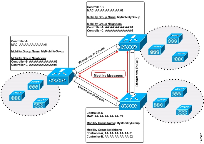
As shown above, each controller is configured with a list of the other members of the mobility group. Whenever a new client joins a controller, the controller sends out a unicast message (or multicast message if mobility multicast is configured) to all of the controllers in the mobility group. The controller to which the client was previously connected passes on the status of the client.

For example, if a controller supports 6000 access points, a mobility group that consists of 24 such controllers supports up to 144,000 access points (24 * 6000 = 144,000 access points).

Mobility groups enable you to limit roaming between different floors, buildings, or campuses in the same enterprise by assigning different mobility group names to different controllers within the same wireless network.

Figure 2. Two Mobility Groups. This figure shows the results of creating distinct mobility group names for two groups of controllers.

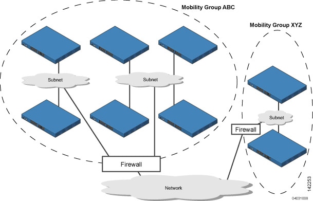
The controllers in the ABC mobility group share access point and client information with each other. The controllers in the ABC mobility group do not share the access point or client information with the XYZ controllers, which are in a different mobility group. Likewise, the controllers in the XYZ mobility group do not share access point or client information with the controllers in the ABC mobility group. This feature ensures mobility group isolation across the network.

Every controller maintains information about its peer controllers in a mobility list. Controllers can communicate across mobility groups and clients may roam between access points in different mobility groups if the controllers are included in each other’s mobility lists. In the following example, controller 1 can communicate with either controller 2 or 3, but controller 2 and controller 3 can communicate only with controller 1 and not with each other. Similarly, clients can roam between controller 1 and controller 2 or between controller 1 and controller 3 but not between controller 2 and controller 3.

Table 1. Example
Controller 1

Mobility group: A

Mobility list:

Controller 1 (group A)

Controller 2 (group A)

Controller 3 (group C) ?

Controller 2

Mobility group: A

Mobility list:

Controller 1 (group A)

Controller 2 (group A)

Controller 3

Mobility group: C

Mobility list:

Controller 1 (group A)

Controller 3 (group C)

In a mobility list, the following combinations of mobility groups and members are allowed:

  • 3 mobility groups with 24 members in each group

  • 12 mobility groups with 6 members in each group

  • 24 mobility groups with 3 members in each group

  • 72 mobility groups with 1 member in each group

The controller supports seamless roaming across multiple mobility groups. During seamless roaming, the client maintains its IP address across all mobility groups; however, Cisco Centralized Key Management (CCKM) and proactive key caching (PKC) are supported only for inter-mobility-group roaming. When a client crosses a mobility group boundary during a roam, the client is fully authenticated, but the IP address is maintained, and mobility tunneling is initiated for Layer 3 roaming.


Note

When a controller is added to a mobility group, some of the APs (which are running in local mode) do not get the complete controllers list updated, those APs are connected to controllers that are in the same mobility group. You can view the controller list in the APs using the command "show capwap client config" AP-NAME command. For example, if the mobility group is for 19 controllers and then you add two more controllers to the mobility group, the AP shows 19 controllers instead of 21 in its list. To address this issue, you can reboot the AP or move it to another controller that is part of the same mobility group to get the controller list updated. This issue is observed in AP1242 connected to different Cisco 5508 WLCs running code 7.6.120.0.

Note

When client moves to a non anchored SSID from an anchored sSSID on foreign, there is a stale entry on foreign .This happens when multicast mobile announce does not reach from foreign to guest anchor due to whatsoever reason, due to this the service is not impacted and configuration goes unnoticed but silently leaks MSCB on GA .There is no debug or error message shown nor does the GA runs a timer per client to cleanup. A HandoffEnd needs to be sent from foreign to Anchor since there is no timer.


Prerequisites for Configuring Mobility Groups

Before you add controllers to a mobility group, you must verify that the following requirements have been met for all controllers that are to be included in the group:

  • IP connectivity must exist between the management interfaces of all controllers.


    Note

    You can verify IP connectivity by pinging the controllers.


    Note

    Mobility control packets can use any interface address as the source, based on routing table. It is recommended that all controllers in the mobility group should have the management interface in the same subnet. A topology where one controller's management interface and other controller's dynamic interface are on same subnet not recommended for seamless mobility.


  • When controllers in the mobility list use different software versions, Layer 2 or Layer 3 clients have limited roaming support. Layer 2 or Layer 3 client roaming is supported only between controllers that use the same version or with controllers that run versions 7.X.X.


    Note

    If you inadvertently configure a controller with a failover controller that runs a different software release, the access point might take a long time to join the failover controller because the access point starts the discovery process in CAPWAP and then changes to LWAPP discovery.


  • All controllers must be configured with the same virtual interface IP address.


    Note

    If necessary, you can change the virtual interface IP address by editing the virtual interface name on the Controller > Interfaces page.


    Note

    If all the controllers within a mobility group are not using the same virtual interface, inter-controller roaming may appear to work, but the handoff does not complete, and the client loses connectivity for a period of time.


  • You must have gathered the MAC address and IP address of every controller that is to be included in the mobility group. This information is necessary because you will be configuring all controllers with the MAC address and IP address of all the other mobility group members.


    Note

    You can find the MAC and IP addresses of the other controllers to be included in the mobility group on the Controller > Mobility Groups page of each controller’s GUI.


  • When you configure mobility groups using a third-party firewall, for example, Cisco PIX, or Cisco ASA, you must open port 16666, and IP protocol 97.

  • For intercontroller CAPWAP data and control traffic, you must open the ports 5247 and 5246.

This table lists the protocols and port numbers that must be used for management and operational purposes:

Table 2. Protocol/Service and Port Number

Protocol/Service

Port Number

SSH/Telnet

TCP Port 22 or 29

TFTP

UDP Port 69

NTP/SNTP

UDP Port 123

SNMP

UDP Port 161 for gets and sets and UDP port 162 for traps.

HTTPS/HTTP

TCP port 443 for HTTPS and port 80 for HTTP

Syslog

TCP port 514

Radius Auth/Account

UDP port 1812 and 1813


Note

To view information on mobility support across controllers with different software versions, see the http://www.cisco.com/c/en/us/td/docs/wireless/compatibility/matrix/compatibility-matrix.html. .


Note

You cannot perform port address translation (PAT) on the firewall. You must configure one-to-one network address translation (NAT).


Configuring Mobility Groups (GUI)

Procedure


Step 1

Choose Controller > Mobility Management > Mobility Groups to open the Static Mobility Group Members page.

This page shows the mobility group name in the Default Mobility Group text box and lists the MAC address and IPv4/IPv6 address of each controller that is currently a member of the mobility group. The first entry is the local controller, which cannot be deleted.

Note 
If you want to delete any of the remote controllers from the mobility group, hover your cursor over the blue drop-down arrow for the desired controller and choose Remove.
Step 2

Perform one of the following to add controllers to a mobility group:

  • If you are adding only one controller or want to individually add multiple controllers, click New.

    OR

  • If you are adding multiple controllers and want to add them in bulk, click EditAll.

Note 
The EditAll option enables you to enter the MAC and IPv4/IPv6 addresses of all the current mobility group members and then copy and paste all the entries from one controller to the other controllers in the mobility group.
Step 3

Click New to open the Mobility Group Member > New page.

Step 4

Add a controller to the mobility group as follows:

  1. In the Member IP Address text box, enter the management interface IPv4/IPv6 address of the controller to be added.

    Note 
    If you are configuring the mobility group in a network where network address translation (NAT) is enabled, enter the IPv4/IPv6 address that is sent to the controller from the NAT device rather than the controller’s management interface IPv4/IPv6 address. Otherwise, mobility will fail among controllers in the mobility group.
  2. In the Member MAC Address text box, enter the MAC address of the controller to be added.

  3. In the Group Name text box, enter the name of the mobility group.

    Note 
    The mobility group name is case sensitive.
  4. In the Hash text box, enter the hash key of the peer mobility controller, which should be a virtual controller in the same domain.

    You must configure the hash only if the peer mobility controller is a virtual controller in the same domain.

    Note 
    Hash is not supported for IPv6 members.
  5. Click Apply to commit your changes. The new controller is added to the list of mobility group members on the Static Mobility Group Members page.

  6. Click Save Configuration.

  7. Repeat Step a through Step e to add all of the controllers in the mobility group.

  8. Repeat this procedure on every controller to be included in the mobility group. All controllers in the mobility group must be configured with the MAC address and IPv4/IPv6 address of all other mobility group members.

The Mobility Group Members > EditAll page lists the MAC address, IPv4/IPv6 address, and mobility group name (optional) of all the controllers currently in the mobility group. The controllers are listed one per line with the local controller at the top of the list.

Note 
If desired, you can edit or delete any of the controllers in the list.
Step 5

Add more controllers to the mobility group as follows:

  1. Click inside the edit box to start a new line.

  2. Enter the MAC address, the management interface IPv4/IPv6 address, and the name of the mobility group for the controller to be added.

    Note 
    You should enter these values on one line and separate each value with one or two spaces.
    Note 
    The mobility group name is case sensitive.
  3. Repeat Step a and Step b for each additional controller that you want to add to the mobility group.

  4. Highlight and copy the complete list of entries in the edit box.

  5. Click Apply to commit your changes. The new controllers are added to the list of mobility group members on the Static Mobility Group Members page.

  6. Click Save Configurationto save your changes.

  7. Paste the list into the text box on the Mobility Group Members > Edit All page of all the other controllers in the mobility group and click Apply and Save Configuration.

Step 6

Choose Mobility Management > Multicast Messaging to open the Mobility Multicast Messaging page.

The names of all the currently configured mobility groups appear in the middle of the page.

Step 7

On the Mobility Multicast Messaging page, check the Enable Multicast Messaging check box to enable the controller to use multicast mode to send Mobile Announce messages to the mobility members. If you leave it unselected, the controller uses unicast mode to send the Mobile Announce messages. The default value is unselected.

Step 8

If you enabled multicast messaging in the previous step, enter the multicast group IPv4 address for the local mobility group in the Local Group Multicast IPv4 Address text box. This address is used for multicast mobility messaging.

Note 
In order to use multicast messaging, you must configure the IPv4 address for the local mobility group.
Note 
In release 8.0, IPv6 is not supported for mobility multicast.
Step 9

Click Apply to commit your changes.

Step 10

If desired, you can also configure the multicast group IPv4 address for non-local groups within the mobility list. To do so, click the name of a non-local mobility group to open the Mobility Multicast Messaging > Edit page, and enter the multicast group IPv4 address for the non-local mobility group in the Multicast IP Address text box.

Note 
If you do not configure the multicast IPv4 address for non-local groups, the controller uses unicast mode to send mobility messages to those members.
Step 11

Click Apply.

Step 12

Click Save Configuration.


Configuring Mobility Groups (CLI)

Procedure


Step 1

Check the current mobility settings by entering this command:

show mobility summary

Step 2

Create a mobility group by entering this command:

config mobility group domain domain_name

Note 

Enter up to 31 case-sensitive ASCII characters for the group name. Spaces are not allowed in mobility group names.

Step 3

Add a group member by entering this command:

config mobility group member add mac_address ip_address

Note 
If you are configuring the mobility group in a network where network address translation (NAT) is enabled, enter the IP address that is sent to the controller from the NAT device rather than the controller’s management interface IP address. Otherwise, mobility will fail among controllers in the mobility group.
Note 

Enter the config mobility group member delete mac_address command if you want to delete a group member.

Step 4

To configure the hash key of a peer mobility controller, which is a virtual controller in the same domain, enter this command:

config mobility group member hash peer-ip-address key

Step 5

Enable or disable multicast mobility mode by entering this command:

config mobility multicast-mode {enable | disable} local_group_multicast_address

where local_group_multicast_address is the multicast group IPv4 address for the local mobility group. This address is used for multicast mobility messaging.

Note 
In order to use multicast messaging, you must configure the IPv4 address for the local mobility group.
Note 
In release 8.0, IPv6 is not supported for mobility multicast.

If you enable multicast mobility mode, the controller uses multicast mode to send Mobile Announce messages to the local group. If you disable multicast mobility mode, the controller uses unicast mode to send the Mobile Announce messages to the local group. The default value is disabled.

Step 6

(Optional) You can also configure the multicast group IPv4 address for non-local groups within the mobility list. To do so, enter this command:

config mobility group multicast-address group_name IP_address

If you do not configure the multicast IPv4 address for non-local groups, the controller uses unicast mode to send mobility messages to those members.

Step 7

Verify the mobility configuration by entering this command:

show mobility summary

Step 8

To see the hash key of mobility group members in the same domain, enter this command:

show mobility group member hash

Step 9

Save your changes by entering this command:

save config

Step 10

Repeat this procedure on every controller to be included in the mobility group. All controllers in the mobility group must be configured with the MAC address and IP address of all other mobility group members.

Step 11

Enable or disable debugging of multicast usage for mobility messages by entering this command:

debug mobility multicast {enable | disable}


Viewing Mobility Group Statistics (GUI)

Procedure


Step 1

Choose Monitor > Statistics > Mobility Statistics to open the Mobility Statistics page.

This page contains the following fields

  • Global Mobility Statistics

    • Rx Errors—Generic protocol packet receive errors, such as packet too short or format incorrect.

    • Tx Errors—Generic protocol packet transmit errors, such as packet transmission fail.

    • Responses Retransmitted—Mobility protocol that uses UDP and resends requests several times if it does not receive a response. Because of network or processing delays, the responder may receive one or more retry requests after it initially responds to a request. This text box shows a count of the response resends.

    • Handoff Requests Received—Total number of handoff requests received, ignored, or responded to.

    • Handoff End Requests Received—Total number of handoff end requests received. These requests are sent by the anchor or foreign controller to notify the other about the close of a client session.

    • State Transitions Disallowed—Policy enforcement module (PEM) that has denied a client state transition, usually resulting in the handoff being terminated.

    • Resource Unavailable—Necessary resource, such as a buffer, was unavailable, resulting in the handoff being terminated.

  • Mobility Initiator Statistics

    • Handoff Requests Sent—Number of clients that have associated to the controller and have been announced to the mobility group.

    • Handoff Replies Received—Number of handoff replies that have been received in response to the requests sent.

    • Handoff as Local Received—Number of handoffs in which the entire client session has been transferred.

    • Handoff as Foreign Received—Number of handoffs in which the client session was anchored elsewhere.

    • Handoff Denys Received—Number of handoffs that were denied.

    • Anchor Request Sent—Number of anchor requests that were sent for a three-party (foreign-to-foreign) handoff. The handoff was received from another foreign controller, and the new controller is requesting the anchor to move the client.

    • Anchor Deny Received—Number of anchor requests that were denied by the current anchor.

    • Anchor Grant Received—Number of anchor requests that were approved by the current anchor.

    • Anchor Transfer Received—Number of anchor requests that closed the session on the current anchor and transferred the anchor back to the requestor.

  • Mobility Responder Statistics

    • Handoff Requests Ignored—Number of handoff requests or client announcements that were ignored because the controller had no knowledge of that client.

    • Ping Pong Handoff Requests Dropped—Number of handoff requests that were denied because the handoff period was too short (3 seconds).

    • Handoff Requests Dropped—Number of handoff requests that were dropped due to either an incomplete knowledge of the client or a problem with the packet.

    • Handoff Requests Denied—Number of handoff requests that were denied.

    • Client Handoff as Local—Number of handoff responses sent while the client is in the local role.

    • Client Handoff as Foreign—Number of handoff responses sent while the client is in the foreign role.

    • Anchor Requests Received—Number of anchor requests received.

    • Anchor Requests Denied—Number of anchor requests denied.

    • Anchor Requests Granted—Number of anchor requests granted.

    • Anchor Transferred—Number of anchors transferred because the client has moved from a foreign controller to a controller on the same subnet as the current anchor.

Step 2

If you want to clear the current mobility statistics, click Clear Stats.


Viewing Mobility Group Statistics (CLI)

Procedure


Step 1

See mobility group statistics by entering this command:

show mobility statistics

Step 2

Clear the current mobility statistics by entering this command:

clear stats mobility