OC-12 Dynamic Packet Transport (DPT) Port Adapter
Bias-Free Language
The documentation set for this product strives to use bias-free language. For the purposes of this documentation set, bias-free is defined as language that does not imply discrimination based on age, disability, gender, racial identity, ethnic identity, sexual orientation, socioeconomic status, and intersectionality. Exceptions may be present in the documentation due to language that is hardcoded in the user interfaces of the product software, language used based on RFP documentation, or language that is used by a referenced third-party product. Learn more about how Cisco is using Inclusive Language.
- Updated:
- September 14, 2007
Chapter: Overview: OC-12c DPT
Overview
This chapter describes the DPT port adapter and contains the following sections:
•![]() DPT Port Adapter Terms and Acronyms
DPT Port Adapter Terms and Acronyms
•![]() Spatial Reuse Protocol Overview
Spatial Reuse Protocol Overview
•![]() LEDs
LEDs
•![]() Cables, Connectors, and Pinouts
Cables, Connectors, and Pinouts
•![]() Port Adapter Slot Locations on the Supported Platforms
Port Adapter Slot Locations on the Supported Platforms
•![]() Identifying Interface Addresses
Identifying Interface Addresses
Port Adapter Overview
The DPT port adapter shown in Figure 1-1 is a dual-width OC-12c port adapter that provides a shared IP over SONET capability in a Cisco 7200 series router, Cisco uBR7246 router, Cisco 7200 VXR router, or Cisco 7500 series router with VIP4 or later. The DPT port adapter is available in four models:
•![]() PA-SRP-OC12MM (multimode fiber)
PA-SRP-OC12MM (multimode fiber)
•![]() PA-SRP-OC12SMI (single-mode fiber, intermediate reach)
PA-SRP-OC12SMI (single-mode fiber, intermediate reach)
•![]() PA-SRP-OC12SML (single-mode fiber, long reach)
PA-SRP-OC12SML (single-mode fiber, long reach)
•![]() PA-SRP-OC12SMX (single-mode fiber, extended reach)
PA-SRP-OC12SMX (single-mode fiber, extended reach)
The DPT port adapter provides Cisco 7200 series, Cisco uBR7246, Cisco 7200 VXR routers, or Cisco 7500 series routers with two SC duplex ports. Each SC duplex port provides the physical connection to an adjacent device in a DPT ring.
The DPT port adapter is designed to be deployed in SONET OC-12c DPT rings. DPT rings can also be connected to SONET Add Drop Multiplexers (ADMs), thus allowing for the creation of small or very large DPT rings.
Functions
The DPT port adapter supports the following functions:
•![]() Accommodates large-scale network topology
Accommodates large-scale network topology
•![]() Leverages fiber-optic capacity at OC-12c line rates
Leverages fiber-optic capacity at OC-12c line rates
•![]() Controls the rate at which new packets are inserted on the media
Controls the rate at which new packets are inserted on the media
•![]() Allows data to obtain fair-shared access to the OC-12c rings
Allows data to obtain fair-shared access to the OC-12c rings
•![]() Implements protection mechanisms, including wrap and unwrap in the event of fiber or node failure
Implements protection mechanisms, including wrap and unwrap in the event of fiber or node failure
•![]() Supports both single-mode and multimode fiber transmissions
Supports both single-mode and multimode fiber transmissions
•![]() Supports access to the SONET DCC channel
Supports access to the SONET DCC channel
Figure 1-1 DPT Port Adapter—Faceplate View

DPT Port Adapter Terms and Acronyms
The following terms and acronyms are used in this publication:
•![]() ADM—Add Drop Multiplexer. Device used to add or drop virtual channels from SONET/SDH into physical tributaries that connect across the ring.
ADM—Add Drop Multiplexer. Device used to add or drop virtual channels from SONET/SDH into physical tributaries that connect across the ring.
•![]() DCC—Data Country Code.
DCC—Data Country Code.
•![]() IPS—Intelligent Protection Switch.
IPS—Intelligent Protection Switch.
•![]() ITU-T—International Telecommunication Union Telecommunication Standardization Sector (formerly the Consultative Committee for International Telegraph and Telephone [CCITT]).
ITU-T—International Telecommunication Union Telecommunication Standardization Sector (formerly the Consultative Committee for International Telegraph and Telephone [CCITT]).
•![]() MAC—Media Access Control.
MAC—Media Access Control.
•![]() MIB—Management Information Base.
MIB—Management Information Base.
•![]() OC-3/STM-1, OC-12c/STM-4c, OC-48c/STM-16c, and so on—Optical Carrier specifications for SONET OC and SDH STM transmission rates.
OC-3/STM-1, OC-12c/STM-4c, OC-48c/STM-16c, and so on—Optical Carrier specifications for SONET OC and SDH STM transmission rates.
•![]() OC-N—SONET multiplexing measure: Optical Carrier Level N, where N indicates the number of 51.84 megabit per second (Mbps) channels.
OC-N—SONET multiplexing measure: Optical Carrier Level N, where N indicates the number of 51.84 megabit per second (Mbps) channels.
•![]() OC-Nc/STM-Nc—Designation in which a lowercase c after N indicates that N channels are concatenated into one logical channel having a bandwidth of N multiplied by the appropriate rate for SONET and SDH. For SONET, N is defined as having the values 3, 12, 48, and 192; for SDH, the legal values are 1, 4, and 16.
OC-Nc/STM-Nc—Designation in which a lowercase c after N indicates that N channels are concatenated into one logical channel having a bandwidth of N multiplied by the appropriate rate for SONET and SDH. For SONET, N is defined as having the values 3, 12, 48, and 192; for SDH, the legal values are 1, 4, and 16.
•![]() SDH—Synchronous Digital Hierarchy. International standard for optical digital transmission at hierarchical rates from 155.520 Mbps (STM-1) to 2.488 gigabits per second (Gbps) (STM-16) and higher.
SDH—Synchronous Digital Hierarchy. International standard for optical digital transmission at hierarchical rates from 155.520 Mbps (STM-1) to 2.488 gigabits per second (Gbps) (STM-16) and higher.
•![]() SONET—Synchronous Optical Network. An American National Standards Institute (ANSI) standard (T1.1051988) for optical digital transmission at hierarchical rates from 51.840 Mbps (OC-1) to 2.488 Gbps (OC-48) and higher.
SONET—Synchronous Optical Network. An American National Standards Institute (ANSI) standard (T1.1051988) for optical digital transmission at hierarchical rates from 51.840 Mbps (OC-1) to 2.488 Gbps (OC-48) and higher.
•![]() SRP—Spatial Reuse Protocol. A Layer 2 MAC protocol for use with SONET and SDH rings that runs over a dual-ring network topology and is characterized by shared media, statistical multiplexing, global fairness, and spatial reuse.
SRP—Spatial Reuse Protocol. A Layer 2 MAC protocol for use with SONET and SDH rings that runs over a dual-ring network topology and is characterized by shared media, statistical multiplexing, global fairness, and spatial reuse.
•![]() STM-N—Synchronous Transport Port Adapter Level N. SDH multiplexing measure, where N indicates the number of 155.52 Mbps channels.
STM-N—Synchronous Transport Port Adapter Level N. SDH multiplexing measure, where N indicates the number of 155.52 Mbps channels.
Spatial Reuse Protocol Overview
Spatial Reuse Protocol (SRP) is a media-independent MAC layer protocol that operates over two counterrotating fiber-optic rings. The dual rings provide survivability of data in case of a failed node or a break in connecting cables by rerouting the data path over the alternate ring. SRP provides a more efficient use of bandwidth by having packets traverse only the part of the ring necessary to get to the destination node. Once the packet has reached the destination node, it is removed from the ring, allowing other parts of the ring to reuse the bandwidth. Data packets travel on one ring, while associated control packets travel in the opposite direction on the alternate ring, ensuring that the data takes the shortest path to its destination. (See Figure 1-2.)
Figure 1-2 DPT Ring
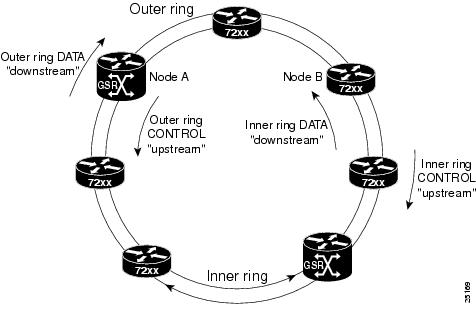
Each node on a DPT ring represents a Cisco 7200 series router, Cisco uBR7246, Cisco 7200 VXR, Cisco 7500 series router, or a Cisco 12000 series Gigabit Switch Router (GSR). A Cisco 7200 series, Cisco uBR7246, Cisco 7200 VXR, or Cisco 7500 series router can be used as an aggregation device for the Cisco 12000 series GSR. The Cisco 7200 series, Cisco uBR7246, Cisco 7200 VXR, or Cisco 7500 seires router collects data from lower-speed interfaces and passes it to the Cisco 12000 series GSR. Typically, more Cisco 7200 series, Cisco uBR7246, Cisco 7200 VXR, or Cisco 7500 series routers aggregate traffic toward fewer Cisco 12000 series GSRs.
A DPT ring can contain up to 32 nodes at one time, with each node holding a map of the ring topology that it continually updates to ensure that data takes the shortest path to its destination. The frequency of the updating can be manually configured. See the "Configuring the DPT Topology Feature" section on page 4-7.
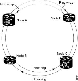
The DPT interface uses the SONET ring architecture, which provides redundancy and protection from a failed node or fiber cut through the use of the Intelligent Protection Switch (IPS). When the DPT ring topology changes because of a node failure, as shown in Figure 1-3, the system software automatically puts the node into pass-through mode, where data continues to pass through the node, but the node is no longer seen on the ring topology map. In the event of a fiber cut, ring wraps are created to redirect data traffic over the alternate ring. (See Figure 1-4.)
In both pass-through mode and wrap mode, data packets not destined for the affected node still reach their destination.
Figure 1-3 DPT Ring with a Node in Pass-Through Mode

Figure 1-4 DPT Ring in Wrap Mode
SONET Distance Limitations
The SONET specification for fiber-optic transmission defines two types of fiber: single-mode and multimode. Signals travel farther through single-mode fiber than through multimode fiber.
The maximum distance for single-mode installations is determined by the amount of light loss in the fiber path. Good-quality single-mode fiber with very few splices can carry an OC-12c/STM-4 signal 50 miles (80 kilometers) or more. Good-quality multimode fiber can carry the signal up to 1640 feet (500 meters). If your environment requires the signal to travel close to the typical maximum distance (as listed in Table 1-1), use an optical time-domain reflectometer (OTDR) to measure the power loss.
1 dBm = decibels per milliwatt 2 nm = nanometer |
LEDs
The eight LEDs on the faceplate of the DPT port adapter (see Figure 1-5), show the DPT port adapter status, as well as the status of the individual ports. Table 1-2 explains the DPT port adapter LEDs.
Figure 1-5 DPT Port Adapter LEDs—Single-Mode Shown

Cables, Connectors, and Pinouts
Use a single-mode or multimode fiber-optic interface cable to connect your Cisco 7200 series, Cisco 7200 VXR, Cisco uBR7246, or Cisco 7500 series router with VIP to another router or switch. In general, multimode cables are gray or orange, and single-mode cables are yellow.

Note ![]() Single-mode and multimode fiber-optic cables are not available from Cisco Systems.
Single-mode and multimode fiber-optic cables are not available from Cisco Systems.
For SONET or SDH single-mode and multimode fiber-optic connections, use one duplex SC-type connector (see Figure 1-6) or two simplex SC-type connectors. (See Figure 1-7.)
Figure 1-6 Duplex SC Cable Connector

Figure 1-7 Simplex SC Cable Connector

Attach either one duplex fiber cable or two simplex fiber cables between the DPT port adapter and the device to which the DPT port adapter is connected. Observe the receive (RX) and transmit (TX) cable relationship shown in Figure 1-8.
Figure 1-8 Attaching Simplex or Duplex Fiber-Optic Cables

The following warnings apply when you work with fiber-optic cable ports.

Warning ![]() Because invisible radiation may be emitted from the aperture of the port when no fiber cable is connected, avoid exposure to radiation and do not stare into open apertures.
Because invisible radiation may be emitted from the aperture of the port when no fiber cable is connected, avoid exposure to radiation and do not stare into open apertures.
Warning ![]() Class 1 laser product (single-mode).
Class 1 laser product (single-mode).
Warning ![]() Class 1 LED product (multimode).
Class 1 LED product (multimode).
Port Adapter Slot Locations on the Supported Platforms
This section discusses port adapter slot locations on the supported platforms. The illustrations that follow summarize slot location conventions on each platform.
Cisco 7200 Series, Cisco 7200 VXR, and Cisco uBR7246 Router Slot Numbering
Figure 1-9 shows a Cisco 7206VXR with a DPT port adapter installed in port adapter slots 3 and 4. In the Cisco 7206 and Cisco 7206VXR port adapter slot 1 is in the lower left position, and port adapter slot 6 is in the upper right position. (The Cisco 7202 and Cisco 7204 are not shown; however, the DPT port adapter can be installed in any two horizontally aligned port adapter slots.)
Figure 1-9 Port Adapter Slots in the Cisco 7206VXR
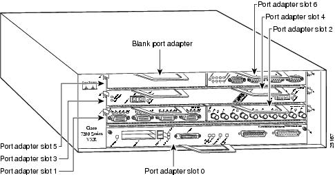
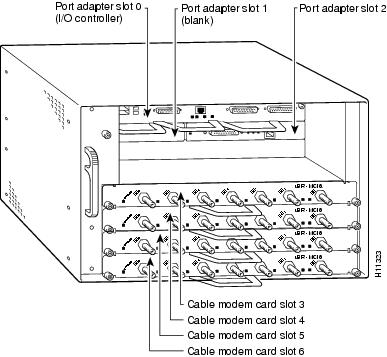
Figure 1-10 shows the slot numbering of port adapters in a Cisco uBR7246 router. The port adapter slots are numbered slot 1 and slot 2 for the Cisco uBR7246. (Slot 0 is always reserved for the Fast Ethernet port on the I/O controller—if present.)
Figure 1-10 Port Adapter Slots in the Cisco uBR7246
Cisco 7500 Series Router with VIP Slot Numbering
Figure 1-11 shows a partial view of a VIP motherboard with installed port adapters. With the motherboard oriented as shown in Figure 1-11, the left port adapter is in port adapter slot 0, and the right port adapter is in port adapter slot 1. The slots are always numbered 0 and 1.
Figure 1-11 VIP Motherboard with Two port adapters Installed—Horizontal Orientation

Note ![]() In the Cisco 7507 and Cisco 7513 chassis, the VIP motherboard is installed vertically.
In the Cisco 7507 and Cisco 7513 chassis, the VIP motherboard is installed vertically.
In the Cisco 7505 chassis, the VIP motherboard is installed horizontally.
Interface processor slots in the Cisco 7500 series routers are numbered as shown in Figure 1-12.
Figure 1-12 Interface Slot Numbers—Cisco 7505 Shown

Identifying Interface Addresses
This section describes how to identify interface addresses for the DPT port adapter in supported platforms. Interface addresses specify the actual physical location of each interface on a router or switch.
Interfaces on the DPT port adapter installed in a router maintain the same address regardless of whether other port adapters are installed or removed. However, when you move a port adapter to a different slot, the first number in the interface address changes to reflect the new port adapter slot number.
Table 1-3 explains how to identify interface addresses of a DPT port adapter.
|
|
|
|
|
|---|---|---|---|
Cisco 7200 series and Cisco 7200 VXR routers |
Port-adapter-slot-number/interface-port-number |
Port adapter slot—1, 3, or 5 for the DPT port adapter (depends on the number of slots in the router)1 Interface port—always 0 |
1/0 |
Cisco uBR7246 router |
Port-adapter-slot-number/interface-port-number |
Port adapter slot—always 11 for the DPT port adapter Interface port—always 0 |
1/0 |
Cisco 7500 series routers with VIP4 |
Port-adapter-slot-number/VIP-bay-number/ |
Port adapter slot—always 11 for the DPT port adapter VIP bay—always 0 or 1 Interface port—always 0 |
1/0/0 |
1 Port adapter slot 0 is reserved for the Fast Ethernet port on the I/O controller (if present). |
Cisco 7200 Series, Cisco 7200 VXR, and Cisco uBR7246 Router Interface Addresses
This section describes how to identify the interface addresses used for the DPT port adapter in Cisco 7200 series, Cisco 7200 VXR, or Cisco uBR7246 routers. The interface address is composed of a two-part number in the format port-adapter-slot-number/interface-port-number. See Table 1-3 for the interface address format.
In Cisco 7200 series and Cisco 7200 VXR routers, port adapter slots are numbered from the lower left to the upper right, beginning with port adapter slot 1 and continuing through slot 4 for the Cisco 7204 and Cisco 7204VXR, and slot 6 for the Cisco 7206 and Cisco 7206VXR. (Port adapter slot 0 is reserved for the optional Fast Ethernet port on the I/O controller—if present.)
The interface address of the DPT port adapter in slots 1 and 2 is 1/0 (port adapter slot 1 and interface 0). If the DPT port adapter was in port adapter slots 3 and 4 this same interface would be numbered 3/0 (port adapter slot 3 and interface 0).
In Cisco uBR7246 router, port adapter slots are numbered slot 1 and slot 2 for the Cisco uBR7246 and Cisco uBR7246VXR. (Slot 0 is always reserved for the Fast Ethernet port on the I/O controller—if present.) The individual interfaces always begin with 0. The number of additional interfaces depends on the number of interface ports on a port adapter.
The interface addresses of the interfaces on a DPT port adapter are 1/0 and 1/1 (port adapter slot 1 and interfaces 0 and 1).
Cisco 7500 Series Router with VIP Interface Addresses
The Cisco 7500 series routers accept port adapters installed with a Versatile Interface Processor (VIP). The interface address of the port adapters is composed of a three-part number in the format slot/bay/port-number. The first number identifies the slot of the router in which the VIP is installed (slot 0 through 12, depending on the number of slots in the router). These port adapter slots are numbered from bottom to top starting with 0.
The second number identifies the bay of the VIP in which the additional port adapter is installed (0 or 1). The bays are numbered from left to right on the VIP. (See Figure 1-11.)
The third number identifies the physical port number on the port adapter. The port numbers always begin at 1 and are numbered from left to right. The number of additional ports (n/1, n/2, and so on) depends on the number of ports on the port adapter.
Note ![]() Although the processor slots in the 7-slot Cisco 7507 and the 13-slot Cisco 7513 and Cisco 7576 are vertically oriented and those in the 5-slot Cisco 7505 are horizontally oriented, all Cisco 7500 series routers use the same method for slot and interface port numbering.
Although the processor slots in the 7-slot Cisco 7507 and the 13-slot Cisco 7513 and Cisco 7576 are vertically oriented and those in the 5-slot Cisco 7505 are horizontally oriented, all Cisco 7500 series routers use the same method for slot and interface port numbering.
If the VIP is installed in slot 3, and the port adapter is installed in bay 1 of the VIP and has a total of 8 ports, the interface addresses of the port adapter are 3/1/0 through 3/1/7 (slot 3, bay 1, ports 0 through 7). If you remove the VIP with the port adapter (see Figure 1-11) from slot 3 and install it in slot 2, the interface addresses become 2/1/0 through 2/1/7. If the port adapter was in bay 0 of the VIP, these same interface addresses would be numbered 2/0/0 through 2/0/7.
 Feedback