The Multiprotocol Label Switching (MPLS) Transport Profile (TP) enables you to create tunnels that provide the transport network service layer over which IP and MPLS traffic traverse. MPLS-TP tunnels enable a transition from Synchronous Optical Networking (SONET) and Synchronous Digital Hierarchy (SDH) time-division multiplexing (TDM) technologies to packet switching to support services with high bandwidth requirements, such as video.
Your software release may not support all the features documented in this module. For the latest feature information and caveats, see the release notes for your platform and software release. To find information about the features documented in this module, and to see a list of the releases in which each feature is supported, see the Feature Information Table at the end of this document.
Use Cisco Feature Navigator to find information about platform support and Cisco software image support. To access Cisco Feature Navigator, go to
www.cisco.com/go/cfn. An account on Cisco.com is not required.
Restrictions for MPLS-TP
MPLS-TPPenultimate hop popping is not supported. Only ultimate hop popping is supported, because label mappings are configured at the MPLS-TP endpoints.
Ethernet subinterfaces are not supported.
IPV6 addressing is not supported.
L2VPN Restrictions
L2VPN interworking is not supported.
Local switching with AToM pseudowire as a backup is not supported.
L2VPN pseudowire redundancy to an AToM pseudowire by one or more attachment circuits is not supported.
PW ID Forward Equivalence Class (FEC) (type 128) is supported, but generalized ID FEC (type 129) is not supported.
Static Pseudowire Operations, Administration, and Maintenance (OAM) protocol and BFD VCCV attachment circuit (AC) status signaling are mutually exclusive protocols. BFD VCCV in failure detection mode can be used with Static Pseudowire OAM protocol.
BFD VCCV AC status signaling cannot be used in pseudowire redundancy configurations. You can use Static Pseudowire OAM instead.
Ping and Trace Restrictions
Ping for Static Pseudowires over MPLS-TP tunnels is not supported.
Pseudowire ping and traceroute functionality for multisegment pseudowires that have one or more static pseudowire segments is not supported.
The following packet format is supported:
A labeled packet with Generic Associated Channel Label (GAL) at the bottom of the label stack.
ACH channel is IP (0x21).
RFC 4379-based IP, UDP packet payload with valid source.
Destination IP address and UDP port 3503.
Default reply mode for (1) is 4--Reply via application level control channel. An echo reply consists of the following elements:
A labeled packet with a GAL label at the bottom of the label stack.
ACH channel is IP (0x21).
RFC 4379-based IP, UDP packet payload with valid source.
Destination IP address and UDP port 3503.
The optional "do not reply" mode may be set.
The following reply modes are not allowed and are disabled in CLI:
2--Reply via an IPv4/IPv6 UDP packet
3--Reply via an IPv4/IPv6 UDP packet with Router Alert
Force-explicit-null is not supported with ping and trace.
Optional Reverse Path Connectivity verification is not supported. See
LSP-Ping Extensions for MPLS-TP (draft-nitinb-mpls-tp-lsp-ping-extensions-01.txt).
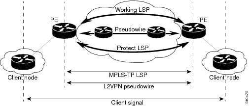
MPLS-TP tunnels provide the transport network service layer over which IP and MPLS traffic traverse. MPLS-TP tunnels help transition from SONET/SDH TDM technologies to packet switching to support services with high bandwidth utilization and lower cost. Transport networks are connection oriented, statically provisioned, and have long-lived connections. Transport networks usually avoid control protocols that change identifiers (like labels). MPLS-TP tunnels provide this functionality through statically provisioned bidirectional label switched paths (LSPs), as shown in the figure below.
MPLS-TP Path Protection
MPLS-TP LSPs support 1-to-1 path protection. You can configure the working and protect LSPs as part of configuring the MPLS-TP tunnel. The working LSP is the primary LSP used to route traffic. The protect LSP is a backup for a working LSP. If the working LSP fails, traffic is switched to the protect LSP until the working LSP is restored, at which time forwarding reverts back to the working LSP.
Bidirectional LSPs
MPLS-TP LSPs are bidirectional and co-routed and are comprised of two unidirectional LSPs that are supported by the MPLS forwarding infrastructure. A TP tunnel consists of a pair of unidirectional tunnels providing a bidirectional LSP. Each unidirectional tunnel can optionally be protected with a protect LSP that activates automatically upon failure conditions.
MPLS-TP OAM Support
Several OAM protocols and messages support the provisioning and maintenance of MPLS-TP tunnels and bidirectional LSPs:
MPLS-TP OAM: GACH: Generic Associated Channel (G-ACh) is the control channel mechanism associated with MPLS LSPs in addition to MPLS pseudowire. The G-ACh Label (GAL) (Label 13) is a generic alert label to identify the presence of the G-ACh in the label packet. It is taken from the reserved MPLS label space.
G-ACh/GAL is used to support in-band OAMs of MPLS LSPs and PWs. The OAM messages are used for fault management, connection verification, continuity check and other functions.
The following OAM messages are forwarded along the specified MPLS LSP:
OAM Fault Management: AIS, LDI and LKR messages. (GAL with fault-OAM channel)
OAM Connection Verification: ping and traceroute messages. (GAL with IP channel by default)
OAM Continuity Check: BFD (non-IP BFD and IP BFD) messages. (GAL with BFD channel or IP channel depending on message format)
The following messages are forwarded along the specified PW:
Static PW OAM messages (static PW status)
PW ping and traceroute messages
PW BFD messages
MPLS-TP OAM: Fault Management: Link Down Indication (LDI), Alarm Indication Signal (AIS), and Lock Report (LKR) messages. LDI messages are generated at midpoint nodes when a failure is detected. At the midpoint, an LDI message will be sent to the endpoint that is reachable with the existing failure. Similarly, LKR messages will be sent from a midpoint node to the reachable endpoint when an interface is administratively shut. AIS messages are not generated by Cisco, but are processed if received. By default, reception of LDI and LKR on the active LSP at an endpoint will cause a path protection switchover, while AIS will not.
MPLS-TP OAM: Fault Management: Emulated Protection Switching for LSP Lockout. Cisco implements a form of Emulated Protection Switching in support of LSP Lockout using customized Fault messages. When a Cisco Lockout message is sent, it does not cause the LSP to be administratively down. The Cisco Lockout message causes a path protection switchover and prevents data traffic from using the LSP. The LSP remains up so that BFD and other OAM messages can continue to traverse it. Maintenance of the LSP can take place (such as reconfiguring or replacing a midpoint LSR). The LSP is shown as UP and OAM can verify connectivity before the LSP is put back into service by removing the lockout. Lockout of the working LSP is not allowed if no protect LSP is configured. Alternatively, lockout of the protect LSP is allowed if no working LSP is configured.
LSP ping and trace: For MPLS-TP connectivity verification, you can use pingmplstp and tracemplstpcommands. You can specify that the echo requests be sent along either the working LSP, the protect LSP, or the active LSP. You can also specify that the echo request be sent on a locked out MPLS-TP tunnel LSP (either working or protect) if the working or protect LSP is explicitly specified.
MPLS-TP OAM: Continuity Check via BFD: You can configure BFD sessions running over MPLS-TP LSPs. BFD sessions run on both the working LSP and the protect LSP. In order to perform a path protection switchover within 60 msec on an MPLS-TP endpoint, the BFD Hardware Offload feature enables the router hardware to construct and send BFD messages, which removes the task from the software path. You do not need to configure the BFD Hardware Offload feature. It works automatically on supported platforms. You must enable BFD.
MPLS-TP Static and Dynamic Multisegment Pseudowires
MPLS-TP supports the following combinations of static and dynamic multisegment pseudowires:
Static-static
Static-dynamic
Dynamic-static
MPLS-TP L2VPN Pseudowire Redundancy for Static and Dynamic Multisegment Pseudowires
MPLS-TP supports one-to-one L2VPN pseudowire redundancy for the following combinations of static and dynamic pseudowires:
Static pseudowire with a static backup pseudowire
Static pseudowire with a dynamic backup pseudowire
Dynamic pseudowire with a static backup pseudowire
MPLS-TP OAM Status for Static and Dynamic Multisegment Pseudowires
With static pseudowires, status notifications can be provided by BFD over VCCV or static pseudowire OAM protocol. However, BFD over VCCV sends only attachment circuit status code notifications. Hop-by-hop notifications of other pseudowire status codes are not supported. Therefore, static pseudowire OAM protocol is preferred. You can acquire per pseudowire OAM for attachment circuit/pseudowire notification over VCCV channel with or without the control word.
MPLS-TP Links and Physical Interfaces
MPLS-TP link numbers may be assigned to physical interfaces only. Bundled interfaces and virtual interfaces are not supported for MPLS-TP link numbers.
The MPLS-TP link is used to create a level of indirection between the MPLS-TP tunnel and midpoint LSP configuration and the physical interface. The mplstplinkcommand is used to associate an MPLS-TP link number with a physical interface and next-hop node. On point-to-point interfaces or Ethernet interfaces designated as point-to-point using the mediump2p command, the next-hop can be implicit, so the mplstplinkcommand just associates a link number to the interface.
Multiple tunnels and LSPs may then refer to the MPLS-TP link to indicate they are traversing that interface. You can move the MPLS-TP link from one interface to another without reconfiguring all the MPLS-TP tunnels and LSPs that refer to the link.
Link numbers must be unique on the router or node.
Tunnel LSPs, whether endpoint or midpoint, use the same identifying information. However, it is entered differently.
At the midpoint, all the information for the LSP is specified with the mplstplsp command, which enters the submode for configuring forward and reverse information for forwarding.
At the midpoint, determining which end is source and which is destination is arbitrary. That is, if you are configuring a tunnel between your router and a coworker's router, then your router is the source. However, your coworker considers his or her router to be the source. At the midpoint, either router could be considered the source. At the midpoint, the forward direction is from source to destination, and the reverse direction is from destination to source.
At the endpoint, the local information (source) either comes from the global router ID and global ID, or from locally configured information using the tpsourcecommand after you enter the command interfacetunnel-tpnumbercommand, where number is the local/source tunnel-number.
At the endpoint, the remote information (destination) is configured using the tpdestination
command after you enter the command interfacetunnel-tpnumber. The tpdestination
command includes the destination node ID, optionally the global ID, and optionally the destination tunnel number. If you do not specify the destination tunnel number, the source tunnel number is used.
At the endpoint, the LSP number is configured in working-lsp or protect-lsp submode. The default is 0 for the working LSP and 1 for the protect LSP.
When configuring the LSPs at the midpoint routers, make that the configuration does not reflect traffic back to the originating node.
Router(config)# mpls label range 1001 1003 static 10000 25000
Specifies a static range of MPLS labels
Configuring the Router ID and Global ID
SUMMARY STEPS
1.enable
2.configureterminal
3.mplstp
4.router-idnode-id
5.global-idnum
DETAILED STEPS
Command or Action
Purpose
Step 1
enable
Example:
Router> enable
Enables privileged EXEC mode.
Enter your password if prompted.
Step 2
configureterminal
Example:
Router# configure terminal
Enters global configuration mode.
Step 3
mplstp
Example:
Router(config)# mpls tp
Enters MPLS-TP configuration mode, from which you can configure MPLS-TP parameters for the router.
Step 4
router-idnode-id
Example:
Router(config-mpls-tp)# router-id10.10.10.10
Specifies the default MPLS-TP router ID, which is used as the default source node ID for all MPLS-TP tunnels configured on the router.
Step 5
global-idnum
Example:
Router(config-mpls-tp)# global-id1
(Optional) Specifies the default global ID used for all endpoints and midpoints. This command makes the router ID globally unique in a multiprovider tunnel. Otherwise, the router ID is only locally meaningful. The global ID is an autonomous system number, which is a controlled number space by which providers can identify each other.
The router ID and global ID are also included in fault messages by routers at tunnel midpoints to help isolate the location of faults.
The bfd-template command allows you to create a BFD template and enter BFD configuration mode. The template can be used to specify a set of BFD interval values. You invoke the template as part of the MPLS-TP tunnel. On platforms that support the BFD Hardware Offload feature and can provide 60-ms cutover for MPLS-TP tunnels, it is recommended to use the higher resolution timers in the BFD template.
When you create the pseudowire class, you specify the parameters of the pseudowire, such as the use of the control word, preferred path, OAM class, and VCCV BFD template.
Enters tunnel interface configuration mode. Tunnel numbers from 0 to 999 are supported.
Step 4
descriptiontunnel-description
Example:
Router(config-if)# descriptionheadendtunnel
(Optional) Specifies a tunnel description.
Step 5
tptunnel-namename
Example:
Router(config-if)# tptunnel-nametunnel22
Specifies the name of the MPLS-TP tunnel. The TP tunnel name is displayed in the showmplstptunnelcommand output. This command is useful for consistently identifying the tunnel at all endpoints and midpoints.
Step 6
tpbandwidthnum
Example:
Router(config-if)#tpbandwidth10000
Specifies the tunnel bandwidth.
Step 7
tpsourcenode-id [global-idnum]
Example:
Router(config-if)# tpsource10.10.11.11global-id10
(Optional) Specifies the tunnel source and endpoint. This command is and not typically used, because the global router ID and global ID can be used to identify the tunnel source at the endpoint. All tunnels on the router generally use the same (globally specified) source information.
Step 8
tpdestinationnode-id[[tunnel-tpnum] global-idnum]
Example:
Router(config-if)# tpdestination10.10.10.10
Specifies the destination node of the tunnel.
Step 9
bfdbfd-template
Example:
Router(config-if)# bfdmpls-tp-bfd-2
Specifies the BFD template.
Step 10
working-lsp
Example:
Router(config-if)# working-lsp
Specifies a working LSP, also known as the primary LSP. This LSP is used to route traffic. This command enters working LSP interface configuration mode (config-if-working).
Step 11
in-labelnum
Example:
Router(config-if-working)# in-label111
Specifies the in label.
Step 12
out-labelnumout-linknum
Example:
Router(config-if-working)# out-label112out-link1
Specifies the out label and out link.
Step 13
exit
Example:
Router(config-if-working)# exit
Exits from working LSP interface configuration mode.
Step 14
protect-lsp
Example:
Router(config-if)# protect-lsp
Specifies a backup for a working LSP. If the working LSP fails, traffic is switched to the protect LSP until the working LSP is restored, at which time forwarding reverts back to the working LSP. This command enters protect LSP interface configuration mode (config-if-protect).
Step 15
in-labelnum
Example:
Router(config-if-protect)# in-label100
Specifies the in label.
Step 16
out-labelnumout-linknum
Example:
Router(config-if-protect)# out-label113out-link2
Specifies the out label and out link.
Step 17
exit
Example:
Router(config-if-protect)# exit
Exits from protect LSP interface configuration mode.
Configuring MPLS-TP LSPs at Midpoints
Note
When configuring the LSPs at the midpoint routers, make that the
configuration does not reflect traffic back to the originating node.
Specifies the in label, out label, and out link numbers.
Configuring MPLS-TP Links and Physical Interfaces
MPLS-TP link numbers may be assigned to physical interfaces only. Bundled interfaces and virtual interfaces are not supported for MPLS-TP link numbers.
Associates an MPLS-TP link number with a physical interface and next-hop node. On point-to-point interfaces or Ethernet interfaces designated as point-to-point using the mediump2p command, the next-hop can be implicit, so the mplstplinkcommand just associates a link number to the interface.
Multiple tunnels and LSPs can refer to the MPLS-TP link to indicate they are traversing that interface. You can move the MPLS-TP link from one interface to another without reconfiguring all the MPLS-TP tunnels and LSPs that refer to the link.
Link numbers a must be unique on the router or node.
Enables Resource Reservation Protocol (RSVP) bandwidth for IP on an interface.
For the Cisco 7600 platform, if you configure non-zero bandwidth for the TP tunnel or at a midpoint LSP, make sure that the interface to which the output link is attached has enough bandwidth available. For example, if three tunnel LSPs run over link 1 and each LSP was assigned 1000 with the tpbandwidth command, the interface associated with link 1 needs bandwidth of 3000 with the iprsvpbandwidth command.
Step 7
exit
Example:
Router(config-if)# exit
Exits interface configuration mode.
Step 8
exit
Example:
Router(config)# exit
Exits global configuration mode.
Step 9
showmplstplink-numbers
Example:
Router# show mpls tp link-numbers
Displays the configured links.
Configuring Static-to-Static Multisegment Pseudowires for MPLS-TP
Configuring Static-to-Dynamic Multisegment Pseudowires for MPLS-TP
When you configure static-to-dynamic pseudowires, you configure the static pseudowire class with the protocolnone command, create a dynamic pseudowire class, then invoke those pseudowire classes with the neighbor commands.
Router(config-vfi)# neighbor 10.111.111.111 123 pw-class atom
Sets up an emulated VC. Specify the IP address and the VC ID of the remote router. Also specify the pseudowire class to use for the emulated VC. Enters config-vfi-neighbor command mode.
Note: Only twoneighbor commands are allowed for each l2 vfi point-to-point command.
Configuring the L2VPN Pseudowire Redundancy for Static Multisegment Pseudowires
Perform the following steps to configure the L2VPN pseudowire
redundancy for static multisegment pseudowires that are backed up with static
or dynamic multisegment pseudowires.
Bidirectional Forwarding Detection (BFD) for the Pseudowire Virtual Circuit Connectivity Verification (VCCV)
RFC 5586
MPLS Generic Associated Channel
Technical Assistance
Description
Link
The Cisco Support and Documentation website provides online resources to download documentation, software, and tools. Use these resources to install and configure the software and to troubleshoot and resolve technical issues with Cisco products and technologies. Access to most tools on the Cisco Support and Documentation website requires a Cisco.com user ID and password.
The following table provides release information about the feature or features described in this module. This table lists only the software release that introduced support for a given feature in a given software release train. Unless noted otherwise, subsequent releases of that software release train also support that feature.
Use Cisco Feature Navigator to find information about platform support and Cisco software image support. To access Cisco Feature Navigator, go to
www.cisco.com/go/cfn. An account on Cisco.com is not required.
Table 1
Feature Information for MPLS-TP
Feature Name
Releases
Feature Information
MPLS Transport Profile
15.1(1)SA
15.3(1)S
Cisco IOS XE Release 3.5S
MPLS Transport Profile (TP) enables you to create tunnels that provide the transport network service layer over which IP and MPLS traffic traverse. MPLS-TP tunnels enable a transition from Synchronous Optical Networking (SONET) and Synchronous Digital Hierarchy (SDH) time-division multiplexing (TDM) technologies to packet switching to support services with high bandwidth requirements, such as video.
In Cisco IOS XE Release 3.5S, support was added for the Cisco ASR 903 Router.
The following commands were introduced or modified:
L2VPN Static to Dynamic PW Interconnection & PW Preferred Path for MPLS-TP Tunnels
Cisco IOS XE Release 3.5S
In Cisco IOS XE Release 3.5S, support was added for the Cisco ASR 903 Router.
MPLS-TP: PW Redundancy for Static PWs
Cisco IOS XE Release 3.5S
In Cisco IOS XE Release 3.5S, support was added for the Cisco ASR 903 Router.
Bidirectional MPLS-TP LSP
Cisco IOS XE Release 3.5S
In Cisco IOS XE Release 3.5S, support was added for the Cisco ASR 903 Router.
MPLS-TP Path Protection
Cisco IOS XE Release 3.5S
In Cisco IOS XE Release 3.5S, support was added for the Cisco ASR 903 Router.
MPLS-TP OAM: GACH
Cisco IOS XE Release 3.5S
In Cisco IOS XE Release 3.5S, support was added for the Cisco ASR 903 Router.
MPLS-TP OAM: Continuity Check via BFD
Cisco IOS XE Release 3.5S
In Cisco IOS XE Release 3.5S, support was added for the Cisco ASR 903 Router.
MPLS-TP OAM: Ping/Trace
Cisco IOS XE Release 3.5S
In Cisco IOS XE Release 3.5S, support was added for the Cisco ASR 903 Router.
MPLS-TP OAM: Fault Management
Cisco IOS XE Release 3.5S
In Cisco IOS XE Release 3.5S, support was added for the Cisco ASR 903 Router.
MPLS TP: IP-less configuration of MPLS TP tunnels
Cisco IOS XE Release 3.5S
In Cisco IOS XE Release 3.5S, support was added for the Cisco ASR 903 Router.
Cisco and the Cisco logo are trademarks or registered trademarks of Cisco and/or its affiliates in the U.S. and other countries. To view a list of Cisco trademarks, go to this URL:
www.cisco.com/go/trademarks. Third-party trademarks mentioned are the property of their respective owners. The use of the word partner does not imply a partnership relationship between Cisco and any other company. (1110R)
Any Internet Protocol (IP) addresses and phone numbers used in this document are not intended to be actual addresses and phone numbers. Any examples, command display output, network topology diagrams, and other figures included in the document are shown for illustrative purposes only. Any use of actual IP addresses or phone numbers in illustrative content is unintentional and coincidental.

 Feedback