
 Feedback
Contents
- MPLS Traffic Engineering Interarea Tunnels
- Finding Feature Information
- Prerequisites for MPLS Traffic Engineering Interarea Tunnels
- Restrictions for MPLS Traffic Engineering Interarea Tunnels
- Information About MPLS Traffic Engineering Interarea Tunnels
- Interarea Tunnels Functionality
- Autoroute Destination Functionality
- CBTS Interaction with Autoroute Destination
- Manually Configured Static Routes Interaction with Autoroute Destination
- Autoroute Announce Interaction with Autoroute Destination
- Forwarding Adjacency Interaction with Autoroute Destination
- MPLS Traffic Engineering Interarea Tunnels Benefits
- How to Configure MPLS Traffic Engineering Interarea Tunnels
- Configuring OSPF for Interarea Tunnels
- Configuring OSPF for ABR Routers
- Configuring OSPF for Non-ABR Routers
- Configuring IS-IS for Interarea Tunnels
- Configuring IS-IS for Backbone Routers
- Configuring IS-IS for Nonbackbone Routers
- Configuring IS-IS for Interfaces
- Configuring MPLS and RSVP to Support Traffic Engineering
- Configuring an MPLS Traffic Engineering Interarea Tunnel
- Configuring an MPLS Traffic Engineering Interarea Tunnel to Use Explicit Paths
- Configuring Explicit Paths
- Configuring an MPLS Traffic Engineering Tunnel with Autoroute Destination
- Configuration Examples for MPLS Traffic Engineering Interarea Tunnels
- Configuring OSPF for Interarea Tunnels Example
- Configuring IS-IS for Interarea Tunnels Example
- Configuring MPLS and RSVP to Support Traffic Engineering Example
- Configuring an MPLS Traffic Engineering Interarea Tunnel Example
- Configuring an MPLS Traffic Engineering Tunnel with Autoroute Destination Example
- Additional References
- Feature Information for MPLS Traffic Engineering Interarea Tunnels
- Glossary
MPLS Traffic Engineering Interarea Tunnels
The MPLS Traffic Engineering: Interarea Tunnels feature allows you to establish Multiprotocol Label Switching (MPLS) traffic engineering (TE) tunnels that span multiple Interior Gateway Protocol (IGP) areas and levels, removing the restriction that had required the tunnel headend and tailend routers both be in the same area. The IGP can be either Intermediate System-to-Intermediate System (IS-IS) or Open Shortest Path First (OSPF).
- Finding Feature Information
- Prerequisites for MPLS Traffic Engineering Interarea Tunnels
- Restrictions for MPLS Traffic Engineering Interarea Tunnels
- Information About MPLS Traffic Engineering Interarea Tunnels
- How to Configure MPLS Traffic Engineering Interarea Tunnels
- Configuration Examples for MPLS Traffic Engineering Interarea Tunnels
- Additional References
- Feature Information for MPLS Traffic Engineering Interarea Tunnels
- Glossary
Finding Feature Information
Your software release may not support all the features documented in this module. For the latest feature information and caveats, see the release notes for your platform and software release. To find information about the features documented in this module, and to see a list of the releases in which each feature is supported, see the Feature Information Table at the end of this document.
Use Cisco Feature Navigator to find information about platform support and Cisco software image support. To access Cisco Feature Navigator, go to www.cisco.com/go/cfn. An account on Cisco.com is not required.
Prerequisites for MPLS Traffic Engineering Interarea Tunnels
Restrictions for MPLS Traffic Engineering Interarea Tunnels
- The dynamic path option feature for TE tunnels (which is specified in the tunnel mpls traffic-eng path-option number dynamic command) is not supported for interarea tunnels. An explicit path identifying the Area Border Routers (ABRs) is required. When there are choices for the ABRs to be used, multiple explicit paths are recommended, each of which identifies a different sequence of ABRs.
- The MPLS TE AutoRoute feature (which is specified in the tunnel mpls traffic-eng autoroute announce command) is not supported for interarea tunnels because you would need to know the network topology behind the tailend router.
- Tunnel affinity (the tunnel mpls traffic-eng affinity command) is not supported for interarea tunnels.
- The reoptimization of tunnel paths is not supported for interarea tunnels.
- Cisco IOS Release 12.4(20)T does not support stateful switchover (SSO) recovery of label-switched paths (LSPs) that include loose hops.
- MPLS traffic engineering supports only a single IGP process/instance. Multiple IGP processes/instances are not supported and MPLS traffic engineering should not be configured in more than one IGP process/instance.
Information About MPLS Traffic Engineering Interarea Tunnels
- Interarea Tunnels Functionality
- Autoroute Destination Functionality
- MPLS Traffic Engineering Interarea Tunnels Benefits
Interarea Tunnels Functionality
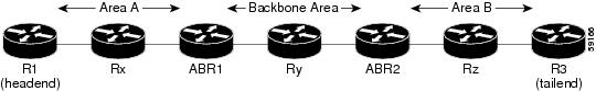
To configure an interarea tunnel, you specify on the headend router a loosely routed explicit path for the tunnel label switched path (LSP) that identifies each ABR the LSP should traverse using the next-address loose command. The headend router and the ABRs along the specified explicit path expand the loose hops, each computing the path segment to the next ABR or tunnel destination.
For example, to configure a TE tunnel from router R1 to router R3 in the simple multiarea network shown in the figure below, you would specify ABR1 and ABR2 as loose hops in the explicit path for the tunnel.
 Note | Rx can be configured as a loose hop as well. In that case, the headend router R1 computes the path to Rx and router Rx computes the path to ABR1. |
To signal the tunnel LSP, the headend router (R1) computes the path to ABR1 and sends a Resource Reservation Protocol (RSVP) Path message specifying the path from itself to ABR1 as a sequence of strict hops followed by the path from ABR1 to the tailend as a sequence of loose hops (ABR2, R3). When ABR1 receives the Path message, it expands the path across the backbone area to ABR2 and forwards the Path message specifying the path from itself to ABR2 as a sequence of strict hops followed by the path from ABR2 to the tunnel tailend (R3) as a loose hop. When ABR2 receives the Path message, it expands the path across the tailend area to R3 and propagates the Path message specifying the path from itself to R2 as a sequence of strict hops.
Note | Cisco IOS Release 12.2(33)SRB supports SSO recovery of LSPs that include loose hops. Cisco IOS Release 12.4(20)T does not support SSO recovery of LSPs that include loose hops. |
Note | With OSPF, if an area is connected to the backbone through a virtual link, there may be more than two ABRs in the path. |
The following MPLS TE features are supported on interarea traffic engineering LSPs:
Autoroute Destination Functionality
The autoroute destination feature allows you to automatically route traffic through a TE tunnel instead of manually configuring static routes.
You enable this feature on a per-tunnel basis by using the tunnel mpls traffic-eng autoroute destination command.
The following sections describe how the autoroute destination feature interacts with other features:
- CBTS Interaction with Autoroute Destination
- Manually Configured Static Routes Interaction with Autoroute Destination
- Autoroute Announce Interaction with Autoroute Destination
- Forwarding Adjacency Interaction with Autoroute Destination
CBTS Interaction with Autoroute Destination
TE tunnels that have the autoroute destination feature enabled can also be configured as class-based traffic shaping (CBTS) tunnel bundle masters or members. Within a CBTS bundle, only the master tunnel with autoroute destination enabled is installed into the Routing Information Base (RIB); that is, the member tunnels are not installed into the RIB.
If member tunnels that have autoroute destination enabled are unconfigured from the bundle, they become regular TE tunnels and TE requests that the static process installs static routes over those tunnels in the RIB. Conversely, when regular TE tunnels with autoroute destination enabled are added to a CBTS bundle as members, TE requests that the static process removes the automatic static routes over those tunnels from the RIB.
Manually Configured Static Routes Interaction with Autoroute Destination
If there is a manually configured static route to the same destination as a tunnel with autoroute destination enabled via the tunnel mpls traffic-eng autoroute destination command, traffic for that destination is load-shared between the static route and the tunnel with autoroute destination enabled.
Autoroute Announce Interaction with Autoroute Destination
For intra-area tunnels, if a tunnel is configured with both autoroute announce and autoroute destination, the tunnel is announced to the RIB by both the IGP and the static process. RIBs prefer static routes, not IGP routes, so the autoroute destination features takes precedence over autoroute announce.
Forwarding Adjacency Interaction with Autoroute Destination
If a tunnel is configured with both forwarding adjacency and autoroute destination, the tunnel is announced to the RIB by both the IGP and the static process. The RIB prefers the static route. However, because the IGP was notified about the tunnel via the forwarding adjacency command and the tunnel information was flooded, forwarding adjacency continues to function.
MPLS Traffic Engineering Interarea Tunnels Benefits
- When it is desirable for the traffic from one router to another router in a different IGP area to travel over TE LSPs, the MPLS Traffic Engineering: Interarea Tunnels feature allows you to configure a tunnel that runs from the source router to the destination router. The alternative would be to configure a sequence of tunnels, each crossing one of the areas between source and destination routers such that the traffic arriving on one such tunnel is forwarded into the next such tunnel.
- The autoroute destination feature prevents you from having to manually configure static routes to route traffic over certain interarea tunnels such as ASBRs.
How to Configure MPLS Traffic Engineering Interarea Tunnels
- Configuring OSPF for Interarea Tunnels
- Configuring IS-IS for Interarea Tunnels
- Configuring MPLS and RSVP to Support Traffic Engineering
- Configuring an MPLS Traffic Engineering Interarea Tunnel
- Configuring an MPLS Traffic Engineering Tunnel with Autoroute Destination
Configuring OSPF for Interarea Tunnels
Configuring OSPF for ABR Routers
For each ABR that is running OSPF, perform the following steps to configure traffic engineering on each area you want tunnels in or across. By having multiple areas and configuring traffic engineering in and across each area, the router can contain changes within the network within an area.
DETAILED STEPS
Configuring OSPF for Non-ABR Routers
For each non-ABR that is running OSPF, perform the following steps to configure OSPF.
Note | MPLS traffic engineering supports only a single IGP process/instance. Multiple IGP processes/instances are not supported and MPLS traffic engineering should not be configured in more than one IGP process/instance. |
DETAILED STEPS
| Command or Action | Purpose | |||
|---|---|---|---|---|
Step 1 |
enable
Example: Router> enable |
Enables privileged EXEC mode.
| ||
Step 2 |
configure
terminal
Example: Router# configure terminal |
Enters global configuration mode. | ||
Step 3 |
router
ospf
process-id
Example: Router(config)# router ospf 1 |
Enables OSPF and enters router configuration mode. The process-id argument is an internally used identification parameter for the OSPF routing process. It is locally assigned and can be any positive integer. Assign a unique value for each OSPF routing process. | ||
Step 4 |
network
ip-address
wildcard-mask
area
area-id
Example: Router(config-router)# network 192.168.10.10 255.255.255.0 area 1 |
Specifies the interfaces on which OSPF is to run and specifies the area to which the interface is connected. | ||
Step 5 |
mpls
traffic-eng
router-id
interface-name
Example: Router(config-router)# mpls traffic-eng router-id Loopback0 |
Specifies that the traffic engineering router identifier for the node is the IP address associated with a given interface. The router identifier is displayed in the show mpls traffic-eng topology path command output.
| ||
Step 6 |
mpls
traffic-eng
area
number
Example: Router(config-router)# mpls traffic-eng area 1 |
Specifies the area that the router is in.
| ||
Step 7 |
end
Example: Router(config-router)# end |
Returns to privileged EXEC mode. |
Configuring IS-IS for Interarea Tunnels
- Configuring IS-IS for Backbone Routers
- Configuring IS-IS for Nonbackbone Routers
- Configuring IS-IS for Interfaces
Configuring IS-IS for Backbone Routers
To configure IS-IS for background (level-1-2) routers, perform the following steps.
Note | MPLS traffic engineering supports only a single IGP process/instance. Multiple IGP processes/instances are not supported and MPLS traffic engineering should not be configured in more than one IGP process/instance. |
DETAILED STEPS
| Command or Action | Purpose | |||
|---|---|---|---|---|
Step 1 |
enable
Example: Router> enable |
Enables privileged EXEC mode.
| ||
Step 2 |
configure
terminal
Example: Router# configure terminal |
Enters global configuration mode. | ||
Step 3 |
router
isis
Example: Router(config)# router isis |
Enables IS-IS routing and specifies an IS-IS process for IP, and places the router in router configuration mode. | ||
Step 4 |
metric-style
wide
Example: Router(config-router)# metric-style wide |
Configures a router to generate and accept only new-style type, length, value objects (TLVs). | ||
Step 5 |
net
nn.nnnn.nnnn.nnnn.nnnn
Example: Router(config-router)# net 10.0000.0100.0000.0010 |
Configures the area ID (area address) and the system ID. | ||
Step 6 |
mpls
traffic-eng
router-id
interface-name
Example: Router(config-router)# mpls traffic-eng router-id Loopback0 |
Specifies that the traffic engineering router identifier for the node is the IP address associated with interface Loopback0. | ||
Step 7 |
mpls
traffic-eng
level-1
Example: Router(config-router)# mpls traffic-eng level-1 |
Turns on MPLS traffic engineering for IS-IS at level 1.
| ||
Step 8 |
mpls
traffic-eng
level-2
Example: Router(config-router)# mpls traffic-eng level-2 |
Turns on MPLS traffic engineering for IS-IS at level 2.
| ||
Step 9 |
interface
typeslot
/
port
Example: Router(config-router)# interface POS1/0 |
Configures an interface type and enters interface configuration mode. | ||
Step 10 |
ip
router
isis
Example: Router(config-if)# ip router isis |
Enables IS-IS routing. Specify this command on each interface on which you want to run IS-IS. | ||
Step 11 |
end
Example: Router(config-if)# end |
Returns to privileged EXEC mode. |
Configuring IS-IS for Nonbackbone Routers
To configure IS-IS for nonbackbone routers, perform the following steps.
Note | MPLS traffic engineering supports only a single IGP process/instance. Multiple IGP processes/instances are not supported and MPLS traffic engineering should not be configured in more than one IGP process/instance. |
DETAILED STEPS
| Command or Action | Purpose | |||
|---|---|---|---|---|
Step 1 |
enable
Example: Router> enable |
Enables privileged EXEC mode.
| ||
Step 2 |
configure
terminal
Example: Router# configure terminal |
Enters global configuration mode. | ||
Step 3 |
router
isis
Example: Router(config)# router isis |
Enables IS-IS routing and specifies an IS-IS process for IP, and places the router in router configuration mode. | ||
Step 4 |
metric-style
wide
Example: Router(config-router)# metric-style wide |
Configures a router to generate and accept only new-style TLVs. | ||
Step 5 |
net
nn.nnnn.nnnn.nnnn.nnnn
Example: Router(config-router)# net 10.0000.2000.0100.0001 |
Configures the area ID (area address) and the system ID. | ||
Step 6 |
mpls
traffic-eng
router-id
interface-name
Example: Router(config-router)# mpls traffic-eng router-id Loopback0 |
Specifies that the traffic engineering router identifier for the node is the IP address associated with interface Loopback0. | ||
Step 7 |
mpls
traffic-eng
{level-1 | level-2} Example: Router(config-router)# mpls traffic-eng level-1 |
Turns on MPLS traffic engineering for IS-IS at level 1.
| ||
Step 8 |
end
Example: Router(config-router)# end |
Returns to privileged EXEC mode. |
Configuring IS-IS for Interfaces
To configure IS-IS for interfaces, perform the following steps.
Note | MPLS traffic engineering supports only a single IGP process/instance. Multiple IGP processes/instances are not supported and MPLS traffic engineering should not be configured in more than one IGP process/instance. |
DETAILED STEPS
| Command or Action | Purpose | |
|---|---|---|
Step 1 |
enable
Example: Router> enable |
Enables privileged EXEC mode.
|
Step 2 |
configure
terminal
Example: Router# configure terminal |
Enters global configuration mode. |
Step 3 |
router
isis
Example: Router(config)# router isis |
Enables IS-IS routing and specifies an IS-IS process for IP. This command places the router in router configuration mode. |
Step 4 |
metric-style
wide
Example: Router(config-router)# metric-style wide |
Configures a router to generate and accept only new-style TLVs. |
Step 5 |
net
nn.nnnn.nnnn.nnnn.nnnn
Example: Router(config-router)# net 10.0000.0100.0000.0010 |
Configures the area ID (area address) and the system ID. |
Step 6 |
mpls
traffic-eng
router-id
interface-name
Example: Router(config-router)# mpls traffic-eng router-id Loopback0 |
Specifies that the traffic engineering router identifier for the node is the IP address associated with interface Loopback0. |
Step 7 |
interface
typeslot
/port Example: Router(config-router)# interface POS1/0 |
Specifies the interface and enters interface configuration mode. |
Step 8 |
ip
router
isis
Example: Router(config-if)# ip router isis |
Enables IS-IS routing. Specify this command on each interface on which you want to run IS-IS. |
Step 9 |
end
Example: Router(config-if)# end |
Returns to privileged EXEC mode. |
Configuring MPLS and RSVP to Support Traffic Engineering
DETAILED STEPS
| Command or Action | Purpose | |
|---|---|---|
Step 1 |
enable
Example: Router> enable |
Enables privileged EXEC mode.
|
Step 2 |
configure
terminal
Example: Router# configure terminal |
Enters global configuration mode. |
Step 3 |
ip
cef
Example: Router(config)# ip cef |
Enables Cisco Express Forwarding on the Route Processor card. |
Step 4 |
mpls
traffic-eng
tunnels
Example: Router(config)# mpls traffic-eng tunnels |
Enables MPLS traffic engineering tunnel signaling on a device. |
Step 5 |
interface
typeslot
/
port
Example: Router(config)# interface Loopback0 |
Specifies the interface and enters interface configuration mode. |
Step 6 |
ip
address
ip-address
mask
[secondary [vrf vrf-name]] Example: Router(config-if)# ip address 192.168.10.10 255.255.255.255 |
Assigns an IP network address and network mask to the interface. |
Step 7 |
ip
rsvp
bandwidth
Example: Router(config-if)# ip rsvp bandwidth |
Enables RSVP for IP on an interface. |
Step 8 |
end
Example: Router(config-if)# end |
Returns to privileged EXEC mode. |
Configuring an MPLS Traffic Engineering Interarea Tunnel
- Configuring an MPLS Traffic Engineering Interarea Tunnel to Use Explicit Paths
- Configuring Explicit Paths
Configuring an MPLS Traffic Engineering Interarea Tunnel to Use Explicit Paths
DETAILED STEPS
| Command or Action | Purpose | |
|---|---|---|
Step 1 |
enable
Example: Router> enable |
Enables privileged EXEC mode.
|
Step 2 |
configure
terminal
Example: Router# configure terminal |
Enters global configuration mode. |
Step 3 |
interface
tunnel-interface
Example: Router(config)# interface Tunel1 |
Configures an interface type and enters interface configuration mode. |
Step 4 |
ip
unnumbered
type
number
Example: Router(config-if)# ip unnumbered Loopback 0 |
Gives the tunnel interface an IP address. An MPLS traffic engineering tunnel interface should be unnumbered because it represents a unidirectional link. |
Step 5 |
tunnel
destination
ip-address
Example: Router(config-if)# tunnel destination 192.168.20.20 |
Specifies the destination for a tunnel. You must enter the MPLS traffic engineering router ID of the destination device. |
Step 6 |
tunnel
mode
mpls
traffic-eng
Example: Router(config-if)# tunnel mode mpls traffic-eng |
Sets the tunnel encapsulation mode to MPLS traffic engineering. |
Step 7 |
tunnel
mpls
traffic-eng
bandwidth
bandwidth
Example: Router(config-if)# tunnel mpls traffic-eng bandwidth 300 |
Configures the bandwidth required for the MPLS traffic engineering tunnel. |
Step 8 |
tunnel
mpls
traffic-eng
path-option
number
explicit
{name path-name | identifier path-number} [lockdown] Example: Router(config-if)# tunnel mpls traffic-eng path-option 1 explicit name path-Tunnel1 |
Configures the tunnel to use a named IP explicit path or a path dynamically calculated from the traffic engineering topology database. The namekeyword must specify the ABRs the tunnel LSP must traverse as loose hops via the next-address loose command. |
Step 9 |
end
Example: Router(config-if)# end |
Returns to privileged EXEC mode. |
Configuring Explicit Paths
DETAILED STEPS
| Command or Action | Purpose | |
|---|---|---|
Step 1 |
enable
Example: Router> enable |
Enables privileged EXEC mode.
|
Step 2 |
configure
terminal
Example: Router# configure terminal |
Enters global configuration mode. |
Step 3 |
ip
explicit-path
name
pathname
Example: Router(config)# ip explicit-path name path-tunnel1 |
Enters IP explicit path configuration mode and creates or modifies the specified path. |
Step 4 |
next-address
[loose | strict] ip-address Example: Router(config-ip-expl-path)# next-address loose 192.168.40.40 |
Specifies the next IP address in the explicit path. In a next-address loose command you must specify each ABR the path must traverse. |
Step 5 |
end
Example: Router(config-ip-expl-path)# end |
Returns to privileged EXEC mode. |
Configuring an MPLS Traffic Engineering Tunnel with Autoroute Destination
DETAILED STEPS
| Command or Action | Purpose | |
|---|---|---|
Step 1 |
enable
Example: Router> enable |
Enables privileged EXEC mode.
|
Step 2 |
configure
terminal
Example: Router# configure terminal |
Enters global configuration mode. |
Step 3 |
interface
tunnel-interface
Example: Router(config)# interface Tunnel1 |
Configures an interface type and enters interface configuration mode. |
Step 4 |
ip
unnumbered
type
number
Example: Router(config-if)# ip unnumbered Loopback 0 |
Gives the tunnel interface an IP address. An MPLS traffic engineering tunnel interface should be unnumbered because it represents a unidirectional link. |
Step 5 |
tunnel
destination
ip-address
Example: Router(config-if)# tunnel destination 192.168.20.20 |
Specifies the destination for a tunnel. You must enter the MPLS traffic engineering router ID of the destination device. |
Step 6 |
tunnel
mode
mpls
traffic-eng
Example: Router(config-if)# tunnel mode mpls traffic-eng |
Sets the tunnel encapsulation mode to MPLS traffic engineering. |
Step 7 |
tunnel
mpls
traffic-eng
bandwidth
bandwidth
Example: Router(config-if)# tunnel mpls traffic-eng bandwidth 300 |
Configures the bandwidth required for the MPLS traffic engineering tunnel. |
Step 8 |
tunnel
mpls
traffic-eng
path-option
number
explicit
{name path-name | identifier path-number} [lockdown] Example: Router(config-if)# tunnel mpls traffic-eng path-option 1 explicit name path-Tunnel1 |
Configures the tunnel to use a named IP explicit path or a path dynamically calculated from the traffic engineering topology database. The namekeyword must specify the ABRs the tunnel LSP must traverse as loose hops via the next-address loose command. |
Step 9 |
tunnel
mpls
traffic-eng
autoroute
destination
Example: Router(config-if)# tunnel mpls traffic-eng autoroute destination |
Automatically routes traffic through a TE tunnel. |
Step 10 |
end
Example: Router(config-if)# end |
Returns to privileged EXEC mode. |
Configuration Examples for MPLS Traffic Engineering Interarea Tunnels
- Configuring OSPF for Interarea Tunnels Example
- Configuring IS-IS for Interarea Tunnels Example
- Configuring MPLS and RSVP to Support Traffic Engineering Example
- Configuring an MPLS Traffic Engineering Interarea Tunnel Example
- Configuring an MPLS Traffic Engineering Tunnel with Autoroute Destination Example
Configuring OSPF for Interarea Tunnels Example
The following configuration fragments show how to configure OSPF for interarea tunnels assuming that:
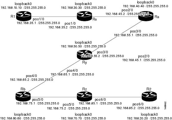
Router R1 OSPF Configuration
router ospf 1
 network 192.168.10.10 0.0.0.0 area 1
 network 192.168.35.0 0.0.0.255 area 1
 mpls traffic-eng router-id Loopback0
 mpls traffic-eng area 1
Router Rx OSPF Configuration
router ospf 1
 network 192.168.30.30 0.0.0.0 area 1
 network 192.168.35.0 0.0.0.255 area 1
 network 192.168.45.0 0.0.0.255 area 1
 mpls traffic-eng router-id Loopback0
 mpls traffic-eng area 1
Router Ra OSPF Configuration
Ra is an ABR for Area 0 and Area 1. Interface POS2/0 is in Area 1 and interface POS3/0 is in Area 0. The mpls traffic-eng area commands configure Ra for IGP TE updates for both areas.
router ospf 1
 network 192.168.40.40 0.0.0.0 area 0
 network 192.168.45.0 0.0.0.255 area 1
 network 192.168.55.0 0.0.0.255 area 0
 mpls traffic-eng router-id Loopback0
 mpls traffic-eng area 0
 mpls traffic-eng area 1
Router Rb OSPF Configuration
Rb is an ABR for Area 0 and Area 2. Interface POS4/0 is in Area 0 and interface POS5/0 is in Area 2. The mpls traffic-eng area commands configure Rb for IGP TE updates for both areas.
router ospf 1
 network 192.168.60.60 0.0.0.0 area 0
 network 192.168.65.0 0.0.0.255 area 0
 network 192.168.75.0 0.0.0.255 area 2
 mpls traffic-eng router-id Loopback0
 mpls traffic-eng area 0
 mpls traffic-eng area 2
Router Rz OSPF Configuration
router ospf 1
 network 192.168.70.70 0.0.0.0 area 2
 network 192.168.75.0 0.0.0.255 area 2
 network 192.168.85.0 0.0.0.255 area 2
 mpls traffic-eng router-id Loopback0
 mpls traffic-eng area 2
Router R2 OSPF Configuration
router ospf 1
 network 192.168.20.20 0.0.0.0 area 2
 network 192.168.85.0 0.0.0.255 area 2
 mpls traffic-eng router-id Loopback0
 mpls traffic-eng area 2
Configuring IS-IS for Interarea Tunnels Example
The following configuration fragments illustrate how to configure IS-IS for interarea tunnels assuming that:
Router R1 IS-IS Configuration
interface POS1/0
 ip router isis
router isis
 metric-style wide
 net 10.0000.0100.0000.0010
 mpls traffic-eng router-id Loopback0
 mpls traffic-eng level-1
Router Rx IS-IS Configuration
clns routing
interface POS1/0
 ip router isis
interface POS2/0
 ip router isis
router isis
 metric-style wide
 net 10.0000.2000.0100.0001
 mpls traffic-eng router-id Loopback0
 mpls traffic-eng level-1
Router Ra IS-IS Configuration
clns routing
interface POS2/0
 ip router isis
interface POS3/0
 ip router isis
router isis
 metric-style wide
 net 10.0000.2000.0200.0002
 mpls traffic-eng router-id Loopback0
 mpls traffic-eng level-1
 mpls traffic-eng level-2
Router Ry IS-IS Configuration
clns routing
interface POS3/0
 ip router isis
interface POS4/0
 ip router isis
router isis
 metric-style wide
 net 10.0000.2000.0300.0003
 mpls traffic-eng router-id Loopback0
 mpls traffic-eng level-2
Router Rb IS-IS Configuration
clns routing
interface POS4/0
 ip router isis
interface POS5/0
 ip router isis
router isis
 metric-style wide
 net 10.0000.2000.0400.0004
 mpls traffic-eng router-id Loopback0
 mpls traffic-eng level-1
 mpls traffic-eng level-2
Configuring MPLS and RSVP to Support Traffic Engineering Example
The following configuration fragments show how to configure MPLS and RSVP to support traffic engineering on the routers.
Router R1 Traffic Engineering Configuration
ip cef
mpls traffic-eng tunnels
interface Loopback0
 ip address 192.168.10.10 255.255.255.255
interface POS1/0
!Each interface supporting MPLS TE must include the following:
 mpls traffic-eng tunnels
 ip rsvp bandwidth
The configuration of routers Rx, Ra, Ry, Rb, Rz, and R2 for traffic engineering operation is similar to that for R1.
Configuring an MPLS Traffic Engineering Interarea Tunnel Example
The following configuration fragments show how to configure an MPLS traffic engineering interarea tunnel. Tunnel1 is configured with a path option that is loosely routed through Ra and Rb.
R1 Interarea Tunnel Configuration
The following commands configure an MPLS TE tunnel to use explicit paths:
interface Tunnel1
 ip unnumbered Loopback0
 tunnel destination 192.168.20.20
 tunnel mode mpls traffic-eng
 tunnel mpls traffic-eng bandwidth 300
 tunnel mpls traffic-eng path-option 1 explicit name path-tunnel1
The following commands configure an explicit path:
ip explicit-path name path-tunnel1
 next-address loose 192.168.40.40
 next-address loose 192.168.60.60
 next-address loose 192.168.20.20  !Specifying the tunnel tailend in the loosely routed
!path is optional.
Note | Generally for an interarea tunnel you should configure multiple loosely routed path options that specify different combinations of ABRs (for OSPF) or level-1-2 boundary routers (for IS-IS) to increase the likelihood that the tunnel will be successfully signaled. In this simple topology there are no other loosely routed paths. |
Additional References
Related Documents
MIBs
Technical Assistance
|
Description |
Link |
|---|---|
|
The Cisco Support website provides extensive online resources, including documentation and tools for troubleshooting and resolving technical issues with Cisco products and technologies. To receive security and technical information about your products, you can subscribe to various services, such as the Product Alert Tool (accessed from Field Notices), the Cisco Technical Services Newsletter, and Really Simple Syndication (RSS) Feeds. Access to most tools on the Cisco Support website requires a Cisco.com user ID and password. |
Feature Information for MPLS Traffic Engineering Interarea Tunnels
The following table provides release information about the feature or features described in this module. This table lists only the software release that introduced support for a given feature in a given software release train. Unless noted otherwise, subsequent releases of that software release train also support that feature.
Use Cisco Feature Navigator to find information about platform support and Cisco software image support. To access Cisco Feature Navigator, go to www.cisco.com/go/cfn. An account on Cisco.com is not required.
| Table 1 | Feature Information for MPLS Traffic Engineering: Interarea Tunnels |
|
Feature Name |
Releases |
Feature Configuration Information |
|---|---|---|
|
MPLS Traffic Engineering: Interarea Tunnels |
12.0(19)ST1 12.0(21)ST 12.2(18)S 12.2(18)SXD 12.2(27)SBC 12.2(28)SB 12.2(33)SRB 12.4(20)T 12.2(33)SRE 15.2(1)S |
The MPLS Traffic Engineering: Interarea Tunnels feature allows you to establish MPLS TE tunnels that span multiple IGP areas and levels, removing the restriction that had required the tunnel headend and tailend routers both to be in the same area. In 12.0(19)ST1, this feature was introduced. In 12.0(21)ST, support was added for the Cisco 10000 series routers. In 12.2(18)S, this feature was integrated. In 12.2(18)SXD, this feature was integrated. In 12.2(27)SBC, this feature was integrated. In 12.2(28)SB, this feature was integrated. In 12.2(33)SRB, support was added for stateful switchover (SSO) recovery of LSPs that include loose hops. In 12.4(20)T, support was eliminated for SSO recovery of LSPs that include loose hops. In 12.2(33)SRE, the MPLS-TE Autoroute Destinations feature was added. In 15.2(1)S the MPLS-TE Autoroute Destinations feature was added. The following commands were added or modified: show ip static route, show mpls traffic-eng autoroute, show mpls traffic-eng tunnels, and tunnel mpls traffic-eng autoroute destination. |
Glossary
ABR --Area Border Router.A router connecting two areas. In OSPF, ABRs belong to both areas and must maintain separate topological databases for each. When an OSPF router has interfaces in more than one area, it is an Area Border Router.
area --A logical set of network segments (for example, one that is OSPF-based) and their attached devices. Areas usually are connected to other areas by routers, making up a single autonomous system. OSPF and IS-IS define their areas differently. OSPF area borders are marked by routers. Some interfaces are in one area, and other interfaces are in another area. With IS-IS, all the routers are completely within an area, and the area borders are on links, not on routers. The routers that connect the areas are level-2 routers, and routers that have no direct connectivity to another area are level-1 routers.
area ID --In an IS-IS router, this area address is associated with the entire router rather than an interface. A router can have up to three area addresses. Both the area ID and the system ID are defined on an IS-IS router by a single address, the Network Entry Title (NET).
autonomous system --A collection of networks under a common administration sharing a common routing strategy. Autonomous systems are subdivided by areas.
Cisco Express Forwarding --An advanced Layer 3 IP switching technology. Cisco Express Forwarding optimizes network performance and scalability for networks that have large and dynamic traffic patterns, such as the Internet, and for networks characterized by intensive Web-based applications or interactive sessions. Cisco Express Forwarding uses a Forwarding Information Base (FIB) to make IP destination prefix-based switching decisions. The FIB is conceptually similar to a routing table or information base. When routing or topology changes occur in the network, the IP routing table is updated, and those changes are reflected in the FIB. The FIB maintains next-hop address information based on the information in the IP routing table.
headend --The upstream, transmit end of a tunnel. The router that originates and maintains the traffic engineering LSP.
IGP --Interior Gateway Protocol. Internet protocol used to exchange routing information within an autonomous system. Examples of common IGPs include OSPF and Routing Information Protocol (RIP).
interarea TE --Ability for a traffic engineering LSP to span multiple areas.
IS-IS --Intermediate System-to-Intermediate System. IS-IS is an OSI link-state hierarchical routing protocol based on DECnet Phase V routing, where intermediate system (IS) routers exchange routing information based on a single metric to determine the network topology.
label switched path (LSP) tunnel --A configured connection between two routers in which label switching is used to carry the packets.
level-1 routers --Routers that are directly connected to other areas. The routers are not in the backbone. MPLS does not run in the background. These routers are also called internal routers.
level-2 routers --Routers that connect two areas. These routers let you run MPLS in the background.
load balancing --The distribution of traffic among multiple paths to the same destination so that the router uses bandwidth efficiently. Load balancing increases the use of network segments, thus increasing effective network bandwidth.
LSP --label switched path. A sequence of hops such as R0...Rn in which a packet travels from R0 to Rn through label switching mechanisms. A label switched path can be chosen dynamically, based on normal routing mechanisms, or through configuration.
mask --A bit combination used to describe which part of an address refers to the network or the subnet and which part refers to the host.
MPLS --Multiprotocol Label Switching. A method for forwarding packets (frames) through a network. It enables routers at the edge of a network to apply labels to packets. ATM switches or existing routers in the network core can switch packets according to the labels with minimal lookup overhead.
OSPF --Open Shortest Path First. Link-state, hierarchical IGP routing algorithm proposed as a successor to Routing Information Protocol (RIP) in the Internet community. OSPF features include least-cost routing, multipath routing, and load balancing.
process ID --Distinguishes one process from another within the device. An OSPF process ID can be any positive integer, and it has no significance outside the router on which it is configured.
router ID --Something by which a router originating a packet can be uniquely distinguished from all other routers. For example, an IP address from one of the router's interfaces.
static routing --A static route is a fixed path preprogrammed by a network administrator. Static routes cannot make use of routing protocols and don't self-update after receipt of routing update messages; they must be updated by hand.
tailend --The downstream, receive end of a tunnel. The router that terminates the traffic engineering LSP.
traffic engineering --The techniques and processes that cause routed traffic to travel through the network on a path other than the one that would have been chosen if standard routing methods were used.
tunnel --A secure communication path between two peers, such as two routers. A traffic engineering tunnel is a label switched tunnel that is used for traffic engineering. Such a tunnel is set up through means other than normal Layer 3 routing; it is used to direct traffic over a path different from the one that Layer 3 routing could cause the tunnel to take.
virtual link --Ordinarily, each area is directly connected to area 0. A virtual link is used for a connection when an area is connected to an area that is one area away from area 0.
Cisco and the Cisco logo are trademarks or registered trademarks of Cisco and/or its affiliates in the U.S. and other countries. To view a list of Cisco trademarks, go to this URL: www.cisco.com/go/trademarks. Third-party trademarks mentioned are the property of their respective owners. The use of the word partner does not imply a partnership relationship between Cisco and any other company. (1110R)
Any Internet Protocol (IP) addresses and phone numbers used in this document are not intended to be actual addresses and phone numbers. Any examples, command display output, network topology diagrams, and other figures included in the document are shown for illustrative purposes only. Any use of actual IP addresses or phone numbers in illustrative content is unintentional and coincidental.