
 Feedback
Contents
- Cisco TrustSec SGT Exchange Protocol IPv4
- Finding Feature Information
- Prerequisites for Cisco TrustSec SGT Exchange Protocol IPv4
- Restrictions for Cisco TrustSec SGT Exchange Protocol IPv4
- Information About Cisco TrustSec SGT Exchange Protocol IPv4
- Security Group Tagging
- Using CTS-SXP for SGT Propagation Across Legacy Access Networks
- Identity-Based Firewall
- VRF-Aware CTS-SXP
- How to Configure the CiscoTrustSec SGT Exchange Protocol IPv4
- Enabling CTS-SXP
- Configuring a CTS-SXP Peer Connection
- Examples
- Configuring the Default CTS-SXP Password
- Configuring the Default CTS-SXP Source IP Address
- Configuring the CTS-SXP Reconciliation Period
- Configuring the CTS-SXP Retry Period
- Creating Syslogs to Capture IP-to-SGT Mapping Changes
- Additional References
- Feature Information for Cisco TrustSec SGT Exchange Protocol IPv4
Cisco TrustSec SGT Exchange Protocol IPv4
First Published: July 25, 2011
Cisco TrustSec (CTS) builds secure networks by establishing domains of trusted network devices. Each device in the domain is authenticated by its peers. Communication on the links between devices in the domain is secured with a combination of encryption, message integrity check, and data-path replay protection mechanisms.
The Security Group Tag (SGT) Exchange Protocol (SXP) is one of several protocols that supports CTS and is referred to in this document as CTS-SXP. CTS-SXP is a control protocol for propagating IP-to-SGT binding information across network devices that do not have the capability to tag packets. CTS-SXP passes IP to SGT bindings from authentication points to upstream devices in the network. This process allows security services on switches, routers, or firewalls to learn identity information from access devices.
- Finding Feature Information
- Prerequisites for Cisco TrustSec SGT Exchange Protocol IPv4
- Restrictions for Cisco TrustSec SGT Exchange Protocol IPv4
- Information About Cisco TrustSec SGT Exchange Protocol IPv4
- How to Configure the CiscoTrustSec SGT Exchange Protocol IPv4
- Additional References
- Feature Information for Cisco TrustSec SGT Exchange Protocol IPv4
Finding Feature Information
Your software release may not support all the features documented in this module. For the latest feature information and caveats, see the release notes for your platform and software release. To find information about the features documented in this module, and to see a list of the releases in which each feature is supported, see the Feature Information Table at the end of this document.
Use Cisco Feature Navigator to find information about platform support and Cisco software image support. To access Cisco Feature Navigator, go to www.cisco.com/go/cfn. An account on Cisco.com is not required.
Prerequisites for Cisco TrustSec SGT Exchange Protocol IPv4
The CTS-SXP network needs to be established before implementing SXP. The CTS-SXP network has the following prerequisites:
- CTS-SXP software runs on all network devices
- Connectivity exists between all network devices
- Cisco Secure Access Control System (ACS) 5.1 operates with a CTS-SXP license
- Directory, DHCP, DNS, certificate authority, and NTP servers function within the network
- Configure the retry open timer command to a different value on different routers.
Restrictions for Cisco TrustSec SGT Exchange Protocol IPv4
- AAA for CTS-SXP uses RADIUS and is supported only by the Cisco Secure Access Control System (ACS), version 5.1 or later.
- 802.1X must be enabled globally for CTS-SXP to perform the Network Device Admission Control (NDAC) authentication process where each network device in the CTS domain can verify the credentials and trustworthiness of its peer device. If 802.1X is disabled globally, NDAC is disabled.
- CTS-SXP is supported only on physical interfaces, not on logical interfaces.
- CTS-SXP does not support IPv6.
- If the default password is configured on a router, the connection on that router should configure the password to use the default password. If the default password is not configured, the connection on that router should configure to not use the password configuration. The configuration of the password option should be consistent across the deployment network.
Information About Cisco TrustSec SGT Exchange Protocol IPv4
- Security Group Tagging
- Using CTS-SXP for SGT Propagation Across Legacy Access Networks
- Identity-Based Firewall
- VRF-Aware CTS-SXP
Security Group Tagging
CTS-SXP uses the device and user credentials acquired during authentication for classifying the packets by security groups (SGs) as they enter the network. This packet classification is maintained by tagging packets on ingress to the CTS-SXP network so that they can be properly identified for the purpose of applying security and other policy criteria along the data path. The Security Group Tag (SGT) allows the network to enforce the access control policy by enabling the endpoint device to act upon the SGT to filter traffic.
Using CTS-SXP for SGT Propagation Across Legacy Access Networks
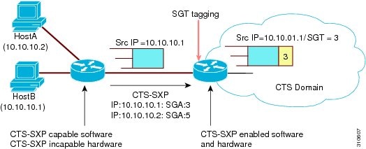
Tagging packets with SGTs requires hardware support. There may be devices in the network that can participate in CTS authentication, but lack the hardware capability to tag packets with SGTs. However, if CTS-SXP is used, then these devices can pass IP-to-SGT mappings to a CTS peer device that has CTS-capable hardware.
CTS-SXP typically operates between ingress access layer devices at the CTS domain edge and distribution layer devices within the CTS domain. The access layer device performs CTS authentication of external source devices to determine the appropriate SGTs for ingress packets. The access layer device learns the IP addresses of the source devices using IP device tracking and (optionally) DHCP snooping, then uses CTS-SXP to pass the IP addresses of the source devices along with their SGTs to the distribution switches. Distribution switches with CTS-capable hardware can use this IP-to-SGT mapping information to tag packets appropriately and to enforce Security Group Access Control List (SGACL) policies as shown in the figure below. An SGACL associates a security group tag with a policy. The policy is enforced when SGT-tagged traffic egresses the CTS domain.
You must manually configure a CTS-SXP connection between a peer without CTS hardware support and a peer with CTS hardware support. The following tasks are required when configuring the CTS-SXP connection:
- If CTS-SXP data integrity and authentication are required, the same CTS-SXP password can be configured on both peer devices. The CTS-SXP password can be configured either explicitly for each peer connection or globally for the device. Although a CTS-SXP password is not required it is recommended.
- Each peer on the CTS-SXP connection must be configured as either a CTS-SXP speaker or CTS-SXP listener. The speaker device distributes the IP-to-SGT mapping information to the listener device.
- A source IP address can be specified to use for each peer relationship or a default source IP address can be configured for peer connections where a specific source IP address is not configured. If no source IP address is specified, then the device uses the interface IP address of the connection to the peer.
CTS-SXP allows multiple hops. That is, if the peer of a device lacking CTS hardware support also lacks CTS hardware support, the second peer can have a CTS-SXP connection to a third peer, continuing the propagation of the IP-to-SGT mapping information until a hardware-capable peer is reached. A device can be configured as a CTS-SXP listener for one CTS-SXP connection as a CTS-SXP speaker for another CTS-SXP connection.
A CTS device maintains connectivity with its CTS-SXP peers by using the TCP keepalive mechanism. To establish or restore a peer connection, the device repeatedly attempts the connection setup by using the configured retry period until the connection is successful or until the connection is removed from the configuration.
Identity-Based Firewall
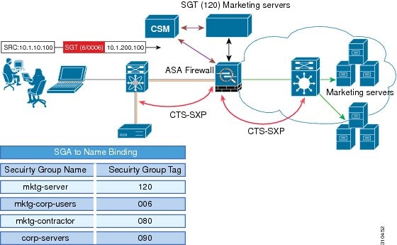
CTS-SXP extends the deployment of additional platforms such as network devices, Identity firewalls, and the wireless controller to additional places on the network. CTS-SXP is used for Identity distribution through inline devices where the identity information is learned from a primary communication path that exists across networks as shown in the figure below.
The SG name is one of the attributes that is used by the Identity firewall to apply enforcement policy. With the SG-name-to-SGT mapping information learned through an authentication server and IP-to-SGT binding learned through CTS-SXP, when a packet arrives, source and destination IP addresses in the packet are used to derive source and destination tags. The Identity firewall applies a policy to the received IP packets based on the configured policy where the SG name or SGT is one of the attributes.
VRF-Aware CTS-SXP
The CTS-SXP implementation of Virtual Routing and Forwarding (VRF) binds a CTS-SXP connection with a specific VRF. It is assumed that the network topology is correctly configured for Layer 2 or Layer 3 VPNs, and that all VRFs are configured before enabling CTS-SXP.
CTS-SXP VRF support can be summarized as follows:
- Only one CTS-SXP connection can be bound to one VRF.
- Different VRFs may have overlapping CTS-SXP peer or source IP addresses.
- IP-to-SGT mappings learned (added or deleted) in one VRF can be updated only in the same VRF domain. The CTS-SXP connection cannot update a mapping bound to a different VRF. If no SXP connection exits for a VRF, IP-SGT mappings for that VRF wonât be updated by SXP.
- Multiple address families per VRF are supported. Therefore, one CTS-SXP connection in a VRF domain can forward both IPv4 and IPv6 IP-to-SGT mappings.
- CTS-SXP has no limitation on the number of connections and number of IP-to-SGT mappings per VRF.
How to Configure the CiscoTrustSec SGT Exchange Protocol IPv4
- Enabling CTS-SXP
- Configuring a CTS-SXP Peer Connection
- Configuring the Default CTS-SXP Password
- Configuring the Default CTS-SXP Source IP Address
- Configuring the CTS-SXP Reconciliation Period
- Configuring the CTS-SXP Retry Period
- Creating Syslogs to Capture IP-to-SGT Mapping Changes
Enabling CTS-SXP
DETAILED STEPS
Configuring a CTS-SXP Peer Connection
The CTS-SXP peer connection must be configured on both devices. One device is the speaker and the other is the listener. When using password protection, make sure to use the same password on both ends.
 Note | If a default CTS-SXP source IP address is not configured and you do not configure a CTS-SXP source address in the connection, the Cisco TrustSec software derives the CTS-SXP source IP address from existing local IP addresses. The CTS-SXP source IP address might be different for each TCP connection initiated from the router. |
DETAILED STEPS
| Command or Action | Purpose | |
|---|---|---|
Step 1 |
enable
Example: Router> enable |
Enables privileged EXEC mode. |
Step 2 |
configure
terminal
Example: Router# configure terminal |
Enters global configuration mode. |
Step 3 |
cts
sxp
connection
peer
ipv4-address {source |
password} {default |
none}
mode {local |
peer} [[listener |
speaker] [vrf
vrf-name]]
Example: Router(config)# cts sxp connection peer 10.20.2.2 password default mode local speaker |
Configures the CTS-SXP peer address connection. The source keyword specifies the IPv4 address of the source device. If no address is specified, the connection uses the default source address, if configured, or the address of the port. The password keyword specifies the password that CTS-SXP uses for the connection using the following options:
The mode keyword specifies the role of the remote peer device:
The optional vrf keyword specifies the VRF to the peer. The default is the default VRF. |
Step 4 |
exit
|
Exits configuration mode. |
Step 5 |
show
cts
sxp {connections |
sgt-map} [brief |
vrf
vrf-name]
Example: Router# show cts sxp connections |
(Optional) Displays CTS-SXP status and connections. |
Examples
This example shows how to enable CTS-SXP and configure the CTS-SXP peer connection on Router_A, a speaker, for connection to Router_B, a listener:
Router# configure terminal
Router_A(config)# cts sxp enable
Router_A(config)# cts sxp default password Cisco123
Router_A(config)# cts sxp default source-ip 10.10.1.1
Router_A(config)# cts sxp connection peer 10.20.2.2 password default mode local speaker
This example shows how to configure the CTS-SXP peer connection on Router_B, a listener, for connection to Router_A, a speaker:
Router# configure terminal
Router_B(config)# cts sxp enable
Router_B(config)# cts sxp default password Cisco123
Router_B(config)# cts sxp default source-ip 10.20.2.2
Router_B(config)# cts sxp connection peer 10.10.1.1 password default mode local listener
This example shows CTS-SXP connections:
Router_B# show cts sxp connections
 SXP              : Enabled
 Default Password : Set
 Default Source IP: 10.10.1.1
Connection retry open period: 10 secs
Reconcile period: 120 secs
Retry open timer is not running
----------------------------------------------
Peer IP          : 10.20.2.2
Source IP        : 10.10.1.1
Conn status      : On
Connection mode  : SXP Listener
Connection inst# : 1
TCP conn fd      : 1
TCP conn password: default SXP password
Duration since last state change: 0:00:21:25 (dd:hr:mm:sec)
Total num of SXP Connections = 1
Configuring the Default CTS-SXP Password
DETAILED STEPS
| Command or Action | Purpose | |||
|---|---|---|---|---|
Step 1 |
enable
Example: Router> enable |
Enables privileged EXEC mode. | ||
Step 2 |
configure
terminal
Example: Router# configure terminal |
Enters global configuration mode. | ||
Step 3 |
cts
sxp
default
password
[0 |
6 |
7]
password
Example: Router(config)# cts sxp default password Cisco123 |
Configures the CTS-SXP default password. You can enter either a clear text password (using the 0 or no option) or an encrypted password (using the 6 or 7 option). The maximum password length is 32 characters.
|
Configuring the Default CTS-SXP Source IP Address
DETAILED STEPS
| Command or Action | Purpose | |||
|---|---|---|---|---|
Step 1 |
enable
Example: Router> enable |
Enables privileged EXEC mode. | ||
Step 2 |
configure
terminal
Example: Router# configure terminal |
Enters global configuration mode. | ||
Step 3 |
cts
sxp
default
source-ip
src-ip-addr
Example: Router(config)# cts sxp default source-ip 10.20.2.2 |
Configures the CTS-SXP default source IP address that is used for all new TCP connections where a source IP address is not specified.
|
Configuring the CTS-SXP Reconciliation Period
After a peer terminates a CTS-SXP connection, an internal hold-down timer starts. If the peer reconnects before the internal hold-down timer expires, the CTS-SXP reconciliation period timer starts. While the CTS-SXP reconciliation period timer is active, the CTS software retains the SGT mapping entries learned from the previous connection and removes invalid entries. The default value is 120 seconds (2 minutes). Setting the CTS-SXP reconciliation period to 0 seconds disables the timer and causes all entries from the previous connection to be removed.
DETAILED STEPS
| Command or Action | Purpose | |
|---|---|---|
Step 1 |
enable
Example: Router> enable |
Enables privileged EXEC mode. |
Step 2 |
configure
terminal
Example: Router# configure terminal |
Enters global configuration mode. |
Step 3 |
cts
sxp
reconciliation
period
seconds
Example: Router(config)# cts sxp reconciliation period 150 |
Sets the CTS-SXP reconciliation timer, in seconds. The range is from 0 to 64000. The default is 120. |
Configuring the CTS-SXP Retry Period
The CTS-SXP retry period determines how often the CTS software retries a CTS-SXP connection. If a CTS-SXP connection is not established successfully, then the CTS software makes a new attempt to set up the connection after the CTS-SXP retry period timer expires. The default value is 2 minutes. Setting the CTS-SXP retry period to 0 seconds disables the timer and retries are not attempted.
DETAILED STEPS
| Command or Action | Purpose | |
|---|---|---|
Step 1 |
enable
Example: Router> enable |
Enables privileged EXEC mode. |
Step 2 |
configure
terminal
Example: Router# configure terminal |
Enters global configuration mode. |
Step 3 |
cts
sxp
retry
period
seconds
Example: Router# cts sxp retry period 160 |
Sets the CTS-SXP retry timer, in seconds. The range is from 0 to 64000. The default is 120. |
Creating Syslogs to Capture IP-to-SGT Mapping Changes
DETAILED STEPS
| Command or Action | Purpose | |||
|---|---|---|---|---|
Step 1 |
enable
Example: Router> enable |
Enables privileged EXEC mode. | ||
Step 2 |
configure
terminal
Example: Router# configure terminal |
Enters global configuration mode. | ||
Step 3 |
cts
sxp
log
binding-changes
Example: Router(config)# cts sxp log binding-changes |
Enables logging for IP-to-SGT binding changes causing CTS-SXP syslogs (sev 5 syslog) to be generated whenever a change to IP-to-SGT binding occurs (add, delete, change). These changes are learned and propagated on the CTS-SXP connection.
|
Additional References
Related Documents
MIBs
Technical Assistance
|
Description |
Link |
|---|---|
|
The Cisco Support and Documentation website provides online resources to download documentation, software, and tools. Use these resources to install and configure the software and to troubleshoot and resolve technical issues with Cisco products and technologies. Access to most tools on the Cisco Support and Documentation website requires a Cisco.com user ID and password. |
Feature Information for Cisco TrustSec SGT Exchange Protocol IPv4
The following table provides release information about the feature or features described in this module. This table lists only the software release that introduced support for a given feature in a given software release train. Unless noted otherwise, subsequent releases of that software release train also support that feature.
Use Cisco Feature Navigator to find information about platform support and Cisco software image support. To access Cisco Feature Navigator, go to www.cisco.com/go/cfn. An account on Cisco.com is not required.
| Table 1 | Feature Information for Cisco TrustSec SGT Exchange Protocol IPv4. |
|
Feature Name |
Releases |
Feature Information |
|---|---|---|
|
Cisco TrustSec SGT Exchange Protocol IPv4 |
12.2(53)SE2 12.2(50)SG5 12.2(33)SXI3 NX-OS 4.2.1 Cisco IOS XE Release 3.4S 15.1(3)S |
The Security Group Tag (SGT) Exchange Protocol (SXP) is one of several protocols that supports CTS and is referred to in this document as CTS-SXP. CTS-SXP is a control protocol for propagating IP-to-SGT binding information across network devices that do not have the capability to tag packets. CTS-SXP passes IP-to-SGT bindings from authentication points to upstream devices in the network. This allows security services on switches, routers, or firewalls to learn identity information from access devices. In Cisco IOS Release 12.2(53)SE2, this feature was introduced on the Cisco Catalyst 3500 and 3750 Series Switches. In Cisco IOS Release 12.2(50)SG5, this feature was introduced on the Cisco Catalyst 4500 Series Switch. In Cisco IOS Release 12.2(33)SXI3, this feature was introduced on the Cisco Catalyst 6500 Series Switches. In Cisco NX-OS 4.2.1 Release, this feature was introduced on the Nexus 7000 Series Switches. This feature was introduced in Cisco IOS Release 15.1(3)S. This feature was introduced in Cisco IOS XE Release 3.4S. The following commands were introduced or modified: cts sxp enable, cts sxp connection peer, show cts sxp, cts sxp default source-ip, cts sxp reconciliation period, cts sxp retry period, cts sxp log binding-changes. |
Cisco and the Cisco Logo are trademarks of Cisco Systems, Inc. and/or its affiliates in the U.S. and other countries. A listing of Cisco's trademarks can be found at www.cisco.com/go/trademarks. Third party trademarks mentioned are the property of their respective owners. The use of the word partner does not imply a partnership relationship between Cisco and any other company. (1005R)
Any Internet Protocol (IP) addresses and phone numbers used in this document are not intended to be actual addresses and phone numbers. Any examples, command display output, network topology diagrams, and other figures included in the document are shown for illustrative purposes only. Any use of actual IP addresses or phone numbers in illustrative content is unintentional and coincidental.