Table Of Contents
Configuring Remote Source-Route Bridging
Configuring RSRB Using Direct Encapsulation
Defining a Ring Group in RSRB Context
Identifying the Remote Peers (Direct Encapsulation)
Enabling SRB on the Appropriate Interfaces
Configuring RSRB Using IP Encapsulation over an FST Connection
Setting Up an FST Peer Name and Assigning an IP Address
Identifying the Remote Peers (FST Connection)
Enabling SRB on the Appropriate Interfaces
Configuring RSRB Using IP Encapsulation over a TCP Connection
Identifying the Remote Peer (TCP Connection)
Enabling SRB on the Appropriate Interfaces
Configuring RSRB Using TCP and LLC2 Local Acknowledgment
Enabling LLC2 Local Acknowledgment Between Two Remote Peer Bridges
Enabling SRB on the Appropriate Interfaces
Enabling Local Acknowledgment and Passthrough
Configuring Direct Frame Relay Encapsulation Between RSRB Peers
Establishing SAP Prioritization
RSRB Network Tuning Configuration Task List
Prioritizing Traffic Based on SNA Local LU Addresses
Assigning a Priority Group to an Input Interface
Configuring the Largest Frame Size
Monitoring and Maintaining the RSRB Network
RSRB Direct Frame Relay Encapsulation Example
RSRB Using IP Encapsulation over a TCP Connection Example
RSRB/TCP Fast-Switching Configuration Example
RSRB Using IP Encapsulation over an FST Connection Example
RSRB Using All Types of Transport Methods Example
RSRB with Local Acknowledgment Example
RSRB with Local Acknowledgment and Passthrough Example
Local Acknowledgment for LLC2 Example
IP for Load Sharing over RSRB Example
Configuring Priority for Locally Terminated Token Ring Interfaces in RSRB Example
Configuring Remote Source-Route Bridging
This chapter describes how to configure remote source-route bridging (RSRB). For a complete description of the RSRB commands mentioned in this chapter, refer to the "Remote Source-Route Bridging Commands" chapter of the Cisco IOS Bridging and IBM Networking Command Reference (Volume 1 of 2). To locate documentation of other commands that appear in this chapter, use the command reference master index or search online.
This chapter contains the following sections:
•
RSRB Network Tuning Configuration Task List
•
To identify the hardware platform or software image information associated with a feature, use the Feature Navigator on Cisco.com to search for information about the feature or refer to the software release notes for a specific release. For more information, see the "Identifying Platform Support for Cisco IOS Software Features" section in the "Using Cisco IOS Software" chapter.
Technology Overview
In contrast to Source-Route Bridging (SRB), which involves bridging between Token Ring media only, RSRB is Cisco's first technique for connecting Token Ring networks over non-Token Ring network segments. (DLSw+ is Cisco's strategic method for providing this function.)
Cisco's RSRB software implementation includes the following features:
•
–
–
–
•
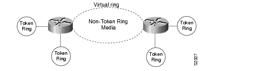
Figure 114 shows an RSRB topology. The virtual ring can extend across any non-Token Ring media supported by RSRB, such as serial, Ethernet, FDDI, and WANs. The type of media you select determines the way you set up RSRB.
Figure 114 RSRB Topology
Note
Configuration Considerations
Only use IP encapsulation over a TCP connection within complex meshed networks to support connections between peers that are separated by multiple hops and can potentially use multiple paths, and where performance is not an issue. Use direct encapsulation in point-to-point connections. In a point-to-point configuration, using TCP adds unnecessary processing overhead. Multiple peer types, however, can be combined to in a single router by following the directions for each peer type. For example, for a peer to support both TCP and FST remote-peers, you would need to define both a source-bridge fst peername and a source-bridge remote-peer command for the local router, using the same local IP address.
FST is fast-switched when it receives or sends frames from Ethernet, Token Ring, or FDDI interfaces. It is also fast-switched when it sends and receives from serial interfaces configured with the High-Level Data Link Control (HDLC) encapsulation. In all other cases, FST is slow-switched.
In cases where FST is fast-switched, in either the Cisco routers configured for FST or in the routers contained within the IP "cloud" between a pair of FST peers, only one path is used at a given time between the two FST peers. A single path greatly decreases the likelihood that frames arrive out of sequence. In the rare cases where frames do arrive out of sequence, the FST code on the receiving peer discards the out-of-order frame. Thus the Token Ring end hosts rarely lose a frame over the FST router cloud, and performance levels remain adequate.
The same conditions are true for any slow-switched topology that provides only a single path (for example, a single X.25 network cloud) between the peers. Similarly, if two slow-switched paths are of very different costs such that one always will be chosen over the other, the chances of having frames received out of sequence are also rare.
However, if two or more slow-switched paths of equal cost exist between the two routers (such as two parallel X.25 networks), the routers alternate in sending packets between the two or more equal-cost paths. This results in a high probability of frames arriving out of sequence at the receiver. In such cases, the FST code disposes of every out-of-sequence packet, leading to a large number of drops. This requires that the end hosts resend frames, greatly reducing overall throughput.
When parallel paths exist, we strongly recommend choosing one as the preferred path. Choose a preferred path by specifying a higher bandwidth for the path that contains the direct connections to the two or more parallel paths on the router.
Do not use FST when the probability exists for frames to lose their order in your network. If you have a network where frames are routinely reordered, it is better to use the TCP protocol for remote source-route bridging. TCP provides the overhead necessary to bring frames back in order on the receiving router. FST, to remain fast, does not provide for such a mechanism, and will discard out-of-order frames.
Logical Link Control, type 2 (LLC2) local acknowledgment can only be enabled with TCP remote peers (as opposed to LAN or direct serial interface remote peers) because the Cisco IOS software needs the reliability of TCP to provide the same reliability that an LLC2 LAN end-to-end connection provides. Therefore, the direct media encapsulation options for the source-bridge remote-peer command cannot be used.
If the LLC2 session between the local host and the router terminates on either side of the connection, the other device will be informed to terminate its connection to its local host.
If the TCP queue length of the connection between the two routers reaches 90 percent of its limit, they send Receiver-not-Ready (RNR) messages to the local hosts until the queue limit is reduced to below this limit.
The configuration of the LLC2 parameters for the local Token Ring interfaces can affect overall performance. Refer to the "Configuring LLC2 and SDLC Parameters" chapter for more details about fine-tuning your network through the LLC2 parameters.
Note
The routers at each end of the LLC2 session execute the full LLC2 protocol, which can result in some overhead. The decision to turn on local acknowledgment for LLC2 should be based on the speed of the backbone network in relation to the Token Ring speed. For LAN segments separated by slow-speed serial links (for example, 56 kbps), the T1 timer problem could occur more frequently. In such cases, it may be wise to turn on local acknowledgment for LLC2. For LAN segments separated by a FDDI backbone, backbone delays will be minimal; in such cases, local acknowledgment for LLC2 should not be turned on. Speed mismatch between the LAN segments and the backbone network is one criterion to be used in the decision to use local acknowledgment for LLC2.
There are some situations (such as host B failing between the time host A sends data and the time
host B receives it) in which host A would behave as if, at the LLC2 layer, data was received when it actually was not, because the device acknowledges that it received data from host A before it confirms that host B can actually receive the data. But because both NetBIOS and SNA have error recovery in situations where an end device goes down, these higher-level protocols will resend any missing or lost data. These transaction request/confirmation protocols exist above LLC2, so they are not affected by tight timers, as is LLC2. They also are transparent to local acknowledgment.If you are using NetBIOS applications, note that there are two NetBIOS timers—one at the link level and one at the next higher level. Local acknowledgment for LLC2 is designed to solve session timeouts at the link level only. If you are experiencing NetBIOS session timeouts, you have two options:
•
•
In a configuration scenario where RSRB is configured between Router A and Router B and both routers are not routing IP, a Host connected to router A through Token Ring (or other LAN media) has no IP connectivity to router B. This restriction exists because IP datagrams received from the Host by
Router A are encapsulated and sent to router B where they can only be de-encapsulated and source-bridged to a tokenring. In this scenario, IP routing is recommended. To enable the Host to reach Router B in this scenario, IP routing should be enabled on Router A's Token Ring interface to which the Host is attached.RSRB Configuration Task List
To configure RSRB, perform the tasks in one of the following sections:
•
•
•
•
•
•
See the "RSRB Configuration Examples" section for examples.
Configuring RSRB Using Direct Encapsulation
Configuring RSRB using the direct encapsulation method uses an HDLC-like encapsulation to pass frames over a single physical network connection between two routers attached to Token Rings. Use this method when you run source-route bridge traffic over point-to-point, single-hop, serial, or LAN media. Although this method does not have the flexibility of the TCP method, it provides better performance because it involves less overhead.To configure a remote source-route bridge to use a point-to-point serial line or a single Ethernet, or single FDDI hop, perform the tasks in the following sections:
•
•
•
Defining a Ring Group in RSRB Context
In our implementation of RSRB, whenever you connect Token Rings using non-Token Ring media, you must treat that non-Token Ring media as a virtual ring by assigning it to a ring group. Every router with which you wish to exchange Token Ring traffic must be a member of this same ring group. These routers are referred to as remote peer bridges. The ring group is therefore made up of interfaces that reside on separate routers.
A ring group must be assigned a ring number that is unique throughout the network. It is possible to assign different interfaces on the same router to different ring groups, if, for example, you plan to administer them as interfaces in separate domains.
To define or remove a ring group, use one of the following commands in global configuration mode, as needed:
:
Identifying the Remote Peers (Direct Encapsulation)
The interfaces that you identify as remote peer bridges must be serial, Ethernet, FDDI, or Token Ring interfaces. On a serial interface, you must use HDLC encapsulation. To identify remote-peer bridges, use the following command in global configuration mode:
Configure a source-bridge remote peer command for each peer router that is part of the virtual ring. When using direct encapsulation, you do not need to configure a local router ID.
Note
To assign a keepalive interval to the remote source-bridging peer, use the following command in interface configuration mode:
Router(config-if)# source-bridge keepalive seconds
Defines the keepalive interval of the remote source-bridging peer.
Enabling SRB on the Appropriate Interfaces
Enable Source-Route Bridging (SRB) on each interface through which SRB traffic will pass. The value you specify in the target ring parameter should be the ring group number you have assigned to the interface. To enable SRB on an interface, use the following command in interface configuration mode:
Router(config-if)# source-bridge local-ring bridge-number target-ring
Enables SRB on an interface.
Configuring RSRB Using IP Encapsulation over an FST Connection
Encapsulating the source-route bridged traffic inside IP datagrams passed over a FST connection between two routers is not as fast as using direct encapsulation. It does, however, outperform IP encapsulation over a TCP connection because it has lower overhead. However, this method is fast-switched and does not support any IP-level functions, including local acknowledgment or fragmentation. Nor is it suitable for use in networks that tend to reorder frame sequences.
To configure a remote source-route bridge to use IP encapsulation over an FST connection, you must perform the tasks in the following sections:
•
•
•
Note
For an example of how to configure RSRB over an FST connection, see the "RSRB Using IP Encapsulation over an FST Connection Example" section.
Setting Up an FST Peer Name and Assigning an IP Address
To set up an FST peer name and provide an IP address to be used by the local router, use the following command in global configuration mode:
Router(config)# source-bridge fst-peername local-interface-address
Sets up an FST peer name and provide the local router with an IP address.
In our implementation of RSRB, whenever you connect Token Rings using non-Token Ring media, you must treat that non-Token Ring media as a virtual ring by assigning it to a ring group. Every router with which you want to exchange Token Ring traffic must be a member of this same ring group. Therefore, after you set up an FST peer name, define a ring group. For more information about defining a ring group, see the "Define a Ring Group in SRB Context" section of the "Configuring Source-Route Bridging" chapter.
Identifying the Remote Peers (FST Connection)
All the routers with which you want to exchange Token Ring traffic are referred to as remote peer bridges. The remote peers can be at the other end of an FST connection. To identify the remote peers, use the following command in global configuration mode:
Router(config)# source-bridge remote-peer ring-group fst ip-address [lf size]
Identifies your peers and specify an FST connection.
Specify one source bridge remote peer command for each peer router that is part of the virtual ring. Also specify one source bridge remote peer command to identify the IP address of the local router. The IP address you specify should be the IP address you want the router to reach.
You can assign a keepalive interval to the RSRB peer. Use the following command in interface configuration mode:
Router(config-if)# source-bridge keepalive seconds
Defines the keepalive interval of the RSRB peer.
Enabling SRB on the Appropriate Interfaces
Enable SRB on each interface through which SRB traffic passes. Make the value of the target ring parameter you specify the ring group number you assigned to the interface. To enable SRB on an interface, use the following command in interface configuration mode:
Router(config-if)# source-bridge local-ring bridge-number target-ring
Enables local SRB on a Token Ring interface.
Configuring RSRB Using IP Encapsulation over a TCP Connection
Encapsulating the source-route bridged traffic inside IP datagrams passed over a TCP connection between two routers offers lower performance, but is the appropriate method to use under the following conditions:
•
•
•
To configure a remote source-route bridge to use IP encapsulation over a TCP connection, you must perform the tasks in the following sections:
•
•
Identifying the Remote Peer (TCP Connection)
In our implementation, whenever you connect Token Rings using non-Token Ring media, you must treat that non-Token Ring media as a virtual ring by assigning it to a ring group. Every router with which you want to exchange Token Ring traffic must be a member of this same ring group. For more information about defining a ring group, see the "Define a Ring Group in SRB Context" section of the "Configuring Source-Route Bridging" chapter.
To identify the remote peers, use the following command in global configuration mode:
Specify one source-bridge remote peer command for each peer router that is part of the virtual ring. Configure an additional source-bridge remote peer command to identify the IP address to be used by the local router.
You can assign a keepalive interval to the RSRB peer. Use the following command in interface configuration mode:
Router(config-if)# source-bridge keepalive seconds
Defines the keepalive interval of the remote source-bridging peer.
Enabling SRB on the Appropriate Interfaces
To enable SRB on an interface, use the following command in interface configuration mode:
Router(config-if)# source-bridge local-ring bridge-number target-ring
Enables local source-route bridging on a Token Ring interface.
The value of the target ring parameter you specify should be the ring group number.
Configuring RSRB Using TCP and LLC2 Local Acknowledgment
Encapsulating source-route bridged traffic inside IP datagrams that traverse a TCP connection between two routers with local acknowledgment enabled is appropriate when you have LANs separated by wide geographic distances and you want to avoid time delays, multiple resending, or loss of user sessions.
LLC2 is an ISO standard data link level protocol used in Token Ring networks. LLC2 was designed to provide reliable sending of data across LAN media and to cause minimal or at least predictable time delays. However, RSRB and WAN backbones created LANs that are separated by wide, geographic distances spanning countries and continents. As a result, LANs have time delays that are longer than LLC2 allows for bidirectional communication between hosts. Local acknowledgment addresses the problem of unpredictable time delays, multiple resending, and loss of user sessions.
In a typical LLC2 session, when one host sends a frame to another host, the sending host expects the receiving host to respond positively or negatively in a predefined period of time commonly called the T1 time. If the sending host does not receive an acknowledgment of the frame it sent within the T1 time, it retries a few times (normally 8 to 10 times). If there is still no response, the sending host drops the session.
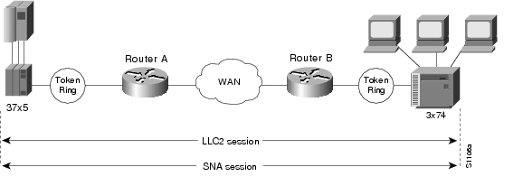
Figure 115 illustrates an LLC2 session. A 37x5 on a LAN segment can communicate with a 3x74 on a different LAN segment separated via a wide-area backbone network. Frames are transported between Router A and Router B using RSRB. However, the LLC2 session between the 37x5 and the 3x74 is still end-to-end; that is, every frame generated by the 37x5 traverses the backbone network to the 3x74, and the 3x74, on receipt of the frame, acknowledges it.
Figure 115 LLC2 Session without Local Acknowledgment
On backbone networks consisting of slow serial links, the T1 timer on end hosts could expire before the frames reach the remote hosts, causing the end host to resend. Resending results in duplicate frames reaching the remote host at the same time as the first frame reaches the remote host. Such frame duplication breaks the LLC2 protocol, resulting in the loss of sessions between the two IBM machines.
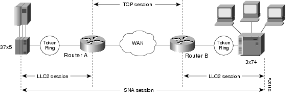
One way to solve this time delay is to increase the timeout value on the end nodes to account for the maximum transit time between the two end machines. However, in networks consisting of hundreds or even thousands of nodes, every machine would need to be reconfigured with new values. With local acknowledgment for LLC2 enabled, the LLC2 session between the two end nodes would not be end-to-end, but instead, would terminate at two local routers. Figure 116 shows the LLC2 session with the 37x5 ending at Router A and the LLC2 session with the 3x74 ending at Router B. Both Router A and Router B execute the full LLC2 protocol as part of local acknowledgment for LLC2.
Figure 116 LLC2 Session with Local Acknowledgment
With local acknowledgment for LLC2 enabled in both routers, Router A acknowledges frames received from the 37x5. The 37x5 still operates as if the acknowledgments it receives are from the 3x74. Router A looks like the 3x74 to the 37x5. Similarly, Router B acknowledges frames received from the 3x74. The 3x74 operates as if the acknowledgments it receives are from the 37x5. Router B looks like the 3x74 to 37x5. The end stations do not time out and lose sessions because the frames no longer have to travel the WAN backbone networks to be acknowledged. Instead, they are locally acknowledged by routers,
Enabling local acknowledgment for LLC2 has the following advantages:
•
•
To configure a remote source-route bridge to use IP encapsulation over a TCP connection, perform the tasks in the following sections:
•
•
Enabling LLC2 Local Acknowledgment Between Two Remote Peer Bridges
In our implementation, whenever you connect Token Rings using non-Token Ring media, you must treat that non-Token Ring media as a virtual ring by assigning it to a ring group. Every router with which you wish to exchange Token Ring traffic must be a member of this same ring group. For more information about defining a ring group, see the "Define a Ring Group in SRB Context" section of the "Configuring Source-Route Bridging" chapter.
To enable LLC2 local acknowledgment, use the following command in global configuration mode:
Router(config)# source-bridge remote-peer ring-group tcp ip-address local-ack
Enables LLC2 local acknowledgment on a per-remote-peer basis.
Use one instance of the source-bridge remote-peer command for each interface you configure for RSRB.
Enabling SRB on the Appropriate Interfaces
To enable SRB on an interface, use the following command in interface configuration mode:
Router(config-if)# source-bridge local-ring bridge-number target-ring
Enables local SRB on a Token Ring interface.
The value of the target ring parameter you specify should be the ring group number.
For an example of how to configure RSRB with local acknowledgment, see the "RSRB with Local Acknowledgment Example" section.
Enabling Local Acknowledgment and Passthrough
To configure some sessions on a few rings to be locally acknowledged while the remaining sessions are passed through, use the following command in global configuration mode:
Router(config)# source-bridge passthrough ring-group
Configures the Cisco IOS software for passthrough.
Configuring Direct Frame Relay Encapsulation Between RSRB Peers
You can configure direct Frame Relay encapsulation to allow the RSRB peers to send RSRB protocol packets on a Frame Relay PVC. This configuration eliminates the overhead introduced by TCP/IP encapsulated Frame Relay packets.
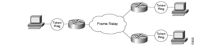
Figure 117 illustrates direct Frame Relay encapsulation between RSRB peers.
Figure 117 RSRB Direct Frame Relay Encapsulation
The RSRB direct encapsulation design can use RFC 1490 format or Cisco Frame Relay encapsulation for routed packets.
To configure RSRB direct Frame Relay encapsulation, use the following commands in interface configuration mode:
Note
Establishing SAP Prioritization
The SAP prioritization feature allows you to use SAP priority lists and filters to specify the priority of one protocol over another across an RSRB or SDLLC WAN.
Defining a SAP Priority List
To establish a SAP priority list, use the following commands in interface configuration mode:
Defining SAP Filters
You can define SAP filters and NetBIOS filters on Token Ring and Ethernet interfaces.
To filter by local service access point (LSAP) address on the RSRB WAN interface, use the following global configuration commands, as needed:
To filter packets by NetBIOS station name on an RSRB WAN interface, use one of the following global configuration commands, as needed:
RSRB Network Tuning Configuration Task List
The following sections describe how to configure features that enhance network performance by reducing the number of packets that traverse the backbone network:
•
•
•
•
Prioritizing Traffic Based on SNA Local LU Addresses
You can prioritize Systems Network Architecture (SNA) traffic on an interface configured for either serial tunnel (STUN) or RSRB communication. The SNA local logical unit (LU) address prioritization feature allows SNA traffic to be prioritized according to the address of the LUs on the FID2 transmission headers. Currently, only dependent LUs are supported. The prioritization takes place on LU-LU traffic between an SNA Node type 5 or Node type 4, and Node type 2.
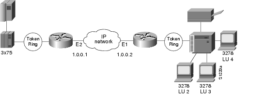
Figure 118 shows how SNA local address prioritization can be used.
Figure 118 SNA Local Address Prioritization
In Figure 118, the IBM mainframe is channel-attached to a 3x75 FEP, which is connected to a cluster controller via RSRB. Multiple 3270 terminals and printers, each with a unique local LU address, are then attached to the cluster controller. By applying SNA local LU address prioritization, each LU associated with a terminal or printer can be assigned a priority; that is, certain users can have terminals that have better response time than others, and printers can have lowest priority.
Note
With the SNA local LU address prioritization feature, you can establish queueing priorities based on the address of the logical unit. To prioritize traffic, use the following commands in global configuration mode:
Enabling Class of Service
To prioritize SNA traffic across the SNA backbone network, you can enable the class of service feature. This feature is useful only between FEP-to-FEP (PU 4-to-PU 4) communication across the non-SNA backbone. It allows important FEP traffic to flow on high-priority queues.
To enable class of service, IP encapsulation over a TCP connection and LLC2 local acknowledgment must be enabled.
To enable class of service, use the following command in global configuration mode:
Assigning a Priority Group to an Input Interface
To assign a priority group to an input interface, use the following command in interface configuration mode:
Router(config-if)# locaddr-priority list-number
Assigns a priority group to an input interface.
Configuring the Largest Frame Size
You can configure the largest frame size that is used to communicate with any peers in the ring group.
Generally, the router and the LLC2 device with which it communicates should support the same maximum SDLC I-frame size. The larger this value, the more efficiently the line is used, thus increasing performance.
Faster screen updates to 3278-style terminals often result by configuring the Token Ring FEP to send as large an I-frame as possible and then allowing the Cisco IOS software to segment the frame into multiple SDLC I-frames.
After you configure the Token Ring FEP to send the largest possible I-frame, configure the software to support the same maximum I-frame size. The default is 516 bytes and the maximum value is 8144 bytes.
To configure the largest frame size, use the following command in global configuration mode:
Router(config)# source-bridge largest-frame ring-group size
Specifies the largest frame size used to communicate with any peers in the ring group.
Monitoring and Maintaining the RSRB Network
To display a variety of information about the RSRB network, use one or more of the following commands in privileged EXEC mode:
In addition to the EXEC-mode commands to maintain the RSRB network, you can use the following command in global configuration mode:
RSRB Configuration Examples
The following sections provide RSRB configuration examples:
•
•
•
•
•
•
•
•
•
•
RSRB Direct Frame Relay Encapsulation Example
The following is the configuration file for direct Frame Relay encapsulation between RSRB peers:
source-bridge ring-group 200source-bridge remote-peer 200 frame-relay interface serial0 30!interface serial 0mtu 3000no ip addressencapsulation frame-relayclockrate 56000frame-relay lmi-type ansiframe-relay map rsrb 30!!interface TokenRing 0ip address 10.10.10.1 255.255.255.0ring-speed 16multiring allsource-bridge active 102 1 200source-bridge spanningRSRB Using IP Encapsulation over a TCP Connection Example
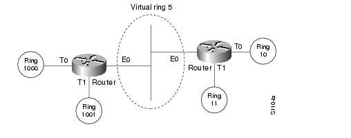
Figure 119 illustrates two routers configured for RSRB using TCP as a transport. Each router has two Token Rings. They are connected by an Ethernet segment over which the source-route bridged traffic will pass. The first router configuration is a source-route bridge at address 131.108.2.29.
Figure 119 RSRB Using TCP as a Transport
Using TCP as the transport, the configuration for the source-route bridge at address 131.108.2.29 as depicted in Figure 119 is as follows:
source-bridge ring-group 5source-bridge remote-peer 5 tcp 131.108.2.29source-bridge remote-peer 5 tcp 131.108.1.27!interface ethernet 0ip address 131.108.4.4 255.255.255.0!interface tokenring 0ip address 131.108.2.29 255.255.255.0source-bridge 1000 1 5source-bridge spanning!interface tokenring 1ip address 131.108.128.1 255.255.255.0source-bridge 1001 1 5source-bridge spanningThe configuration of the source-route bridge at 131.108.1.27 is as follows:
source-bridge ring-group 5source-bridge remote-peer 5 tcp 131.108.2.29source-bridge remote-peer 5 tcp 131.108.1.27!interface ethernet 0ip address 131.108.4.5 255.255.255.0!interface tokenring 0ip address 131.108.1.27 255.255.255.0source-bridge 10 1 5source-bridge spanning!interface tokenring 1ip address 131.108.131.1 255.255.255.0source-bridge 11 1 5source-bridge spanningRSRB/TCP Fast-Switching Configuration Example
The following configuration enables RSRB/TCP fast switching:
source-bridge ring group 100RSRB Using IP Encapsulation over an FST Connection Example
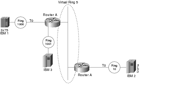
Figure 120 shows two routers connecting IBM hosts on Token Rings through an Ethernet backbone.
Figure 120 RSRB Using FST as a Transport
This configuration example enables IP encapsulation over an FST connection. In this configuration, the source-bridge fst-peername global configuration command is used to provide an IP address for the local router. The source-bridge ring-group global configuration command is used to define a ring group. The source-bridge remote peer command with the fst option is used to associate the remote peer's IP address with the router's ring group and specify the remote peer's remote source-route bridging protocol version number. Because all FST peers support version 2 RSRB, the version keyword is always specified.
The configuration of the source-route bridge at 131.108.2.29 is as follows:
source-bridge fst-peername 131.108.2.29source-bridge ring-group 5source-bridge remote-peer 5 fst 131.108.1.27!interface ethernet 0ip address 131.108.4.4 255.255.255.0!interface tokenring 0ip address 131.108.2.29 255.255.255.0source-bridge 1000 1 5source-bridge spanning!interface tokenring 1ip address 131.108.128.1 255.255.255.0source-bridge 1001 1 5source-bridge spanningThe configuration of the source-route bridge at 131.108.1.27 is as follows:
source-bridge fst-peername 131.108.1.27source-bridge ring-group 5source-bridge remote-peer 5 fst 131.108.2.29!interface ethernet 0ip address 131.108.4.5 255.255.255.0!interface tokenring 0ip address 131.108.1.27 255.255.255.0source-bridge 10 1 5source-bridge spanning!interface tokenring 1ip address 131.108.131.1 255.255.255.0source-bridge 11 1 5source-bridge spanningRSRB Using All Types of Transport Methods Example
Figure 121 shows a router configured for RSRB using all types of transport methods.
Figure 121 RSRB Using All Types of Transport Methods
The configuration for the network in Figure 121 is as follows:
source-bridge fst-peername 131.108.251.1source-bridge ring-group 5source-bridge remote-peer 5 interface serial0source-bridge remote-peer 5 interface serial1source-bridge remote-peer 5 interface Ethernet0 0000.0c00.1234source-bridge remote-peer 5 tcp 131.108.251.1source-bridge remote-peer 5 fst 131.108.252.4source-bridge remote-peer 5 tcp 131.108.253.5!interface tokenring 0source-bridge 1 1 5source-bridge spanning!interface ethernet 0ip address 131.108.251.1 255.255.255.0The two peers using the serial transport method only function correctly if routers at the other end of the serial line have been configured to use the serial transport. The peers must also belong to the same ring group.
RSRB with Local Acknowledgment Example
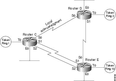
In Figure 122, a triangular configuration provides the maximum reliability with minimal cost, and one of the links is doubled to gain better bandwidth. In addition to IP and SRB traffic, AppleTalk is also routed between all the sites. In this configuration, all the sessions between Router C and Router D are locally acknowledged. All the sessions between Router C and Router E are not locally acknowledged and are configured for normal remote source-route bridging. This example shows that not every peer must be locally acknowledged and that local acknowledgment can be turned on or off at the customer's discretion.
Figure 122 RSRB with Local Acknowledgment—Simple Configuration
The configuration for each of the routers in Figure 122 follows.
Router C
appletalk routing!source-bridge ring-group 5source-bridge remote-peer 5 tcp 132.21.1.1source-bridge remote-peer 5 tcp 132.21.2.6 local-acksource-bridge remote-peer 5 tcp 132.21.10.200!interface tokenring 0ip address 132.21.1.1 255.255.255.0source-bridge 1 1 5source-bridge spanningmultiring all!interface ethernet 0ip address 132.21.4.25 255.255.255.0appletalk address 4.25appletalk zone Twilight!interface serial 0ip address 132.21.16.1 255.255.255.0appletalk address 16.1appletalk zone Twilight!interface serial 1ip address 132.21.17.1 255.255.255.0appletalk address 17.1appletalk zone Twilight!interface serial 2ip address 132.21.18.1 255.255.255.0appletalk address 18.1appletalk zone Twilight!router igrp 109network 132.21.0.0!hostname RouterCRouter D
appletalk routing!source-bridge ring-group 5source-bridge remote-peer 5 tcp 132.21.1.1 local-acksource-bridge remote-peer 5 tcp 132.21.2.6source-bridge remote-peer 5 tcp 132.21.10.200!interface tokenring 0ip address 132.21.2.6 255.255.255.0source-bridge 2 1 5source-bridge spanningmultiring all!interface ethernet 0ip address 132.21.5.1 255.255.255.0appletalk address 5.1appletalk zone Twilight!interface serial 0ip address 132.21.16.2 255.255.255.0appletalk address 16.2appletalk zone Twilight!interface serial 1ip address 132.21.19.1 255.255.255.0appletalk address 19.1appletalk zone Twilight!router igrp 109network 132.21.0.0!hostname RouterDRouter E
appletalk routing!source-bridge ring-group 5source-bridge remote-peer 5 tcp 132.21.1.1source-bridge remote-peer 5 tcp 132.21.2.6source-bridge remote-peer 5 tcp 132.21.10.200!interface tokenring 0ip address 132.21.10.200 255.255.255.0source-bridge 10 1 5source-bridge spanningmultiring all!interface ethernet 0ip address 132.21.7.1 255.255.255.0appletalk address 7.1appletalk zone Twilight!interface serial 0ip address 132.21.19.2 255.255.255.0appletalk address 19.2appletalk zone Twilight!interface serial 1ip address 132.21.17.2 255.255.255.0appletalk address 17.2appletalk zone Twilight!interface serial 2ip address 132.21.18.2 255.255.255.0appletalk address 18.2appletalk zone Twilight!router igrp 109network 132.21.0.0!hostname RouterERSRB with Local Acknowledgment and Passthrough Example
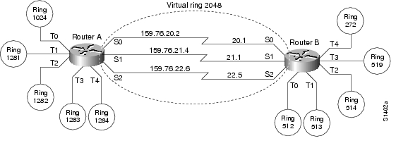
Figure 123 shows two routers configured for RSRB with local acknowledgment and passthrough over the three serial lines that connect these routers. In the example, five Token Rings connect to each of these routers.
Figure 123 Network Topology for RSRB with Local Acknowledgment and Passthrough
The configuration files for each of these routers follows.
Router A
source-bridge ring-group 2048source-bridge remote-peer 2048 tcp 159.76.1.250 local-ack version 2source-bridge remote-peer 2048 tcp 159.76.7.250 version 2source-bridge passthrough 1281source-bridge passthrough 1282source-bridge passthrough 1283source-bridge passthrough 1284!interface tokenring 0ip address 159.76.7.250 255.255.255.0llc2 ack-max 1llc2 t1-time 1800llc2 idle-time 29000llc2 ack-delay-time 5source-bridge 1024 1 2048source-bridge spanningearly-token-releasemultiring all!interface tokenring 1ip address 159.76.8.250 255.255.255.0clns-speed 4clns mtu 464source-bridge 1281 1 2048source-bridge spanningmultiring all!interface tokenring 2ip address 159.76.9.250 255.255.255.0ring-speed 4clns mtu 4464source-bridge 1282 1 2048source-bridge spanningmultiring all!interface tokenring 3ip address 159.76.10.250 255.255.255.0ring speed 4clns mtu 4464source-bridge 1283 1 2048source-bridge spanningmultiring all!interface tokenring 4ip address 159.78.11.250 255.255.255.0ring speed 4clns mtu 4464source-bridge 1284 1 2048source-bridge spanningmultiring all!interface serial 0ip address 159.76.20.2 255.255.255.0!interface serial 1ip address 159.76.21.4 255.255.255.0!interface serial 2ip address 159.76.22.6 255.255.255.0shutdown! interface serial 3no ip addressshutdownRouter B
source-bridge ring-group 2048source-bridge remote-peer 2048 tcp 159.76.1.250 version 2source-bridge remote-peer 2048 tcp 159.76.7.250 local-ack version 2!interface tokenring 0ip address 159.76.1.250 255.255.255.0llc2 ack-max 2llc2 t1-time 1900llc2 idle-time 29000llc2 ack-delay-time 5source-bridge 512 1 2048source-bridge spanningearly-token-releasemultiring all!interface tokenring 1ip address 159.76.2.250 255.255.255.0ring-speed 16clns mtu 8136!source-bridge 513 1 2048source-bridge spanningearly-token-releasemultiring all!interface tokenring 2ip address 159.76.3.250 255.255.255.0ring speed 16clns mtu 8136source-bridge 514 1 2048source-bridge spanningearly-token-releasemultiring all!interface tokenring 3ip address 159.76.4.250 255.255.255.0ring-speed 4clns mtu 4464source-bridge 519 2 2043source-bridge spanningmultiring all!interface tokenring 4ip address 159.76.5.250 255.255.255.0ring-speed 4clns mtu 4464source-bridge 272 2 2048source-bridge spanningmultiring all!interface serial 0ip address 159.76.20.1 255.255.255.0!interface serial 1ip address 159.76.21.3 255.255.255.0!interface serial 2ip address 159.76.22.5 255.255.255.0!interface serial 3no ip addressshutdownLocal Acknowledgment for LLC2 Example
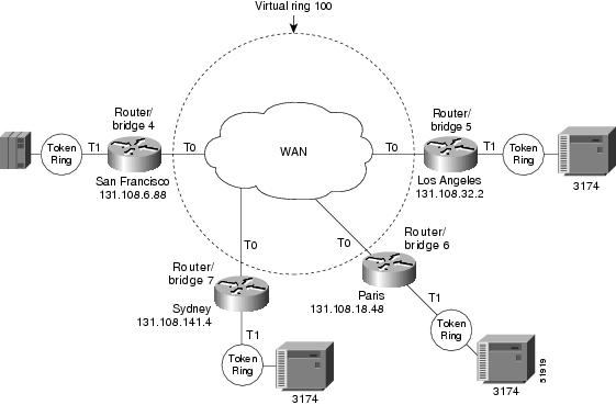
Figure 124 shows an IBM FEP located in San Francisco communicating with IBM 3174 cluster controller hosts in Sydney, Paris, and Los Angeles. The session between the FEP and the IBM 3174 system in Los Angeles is not locally terminated, because the distance is great enough to cause timeouts on the line. However, the sessions to Paris and Sydney are locally terminated.
Figure 124 RSRB with Local Acknowledgment—Complex Configuration
The configuration for each of these routers follows.
Router/Bridge 4 in San Francisco
source-bridge ring-group 100! use direct encapsulation across serial link to Los Angelessource-bridge remote-peer 100 direct 131.108.32.2! use fast sequenced transport with local termination to Parissource-bridge remote-peer 100 tcp 131.108.18.48 local-ack! use tcp encapsulation with local termination to Sydneysource-bridge remote-peer 100 tcp 131.108.141.4 local-ack!interface tokenring 0! source ring 1, bridge 4, destination ring 100source-bridge 1 4 100! receive up to seven frames before sending an acknowledgmentllc2 ack-max 7! allow a 30 msec delay before I-frames must be acknowledgedllc2 ack-delay-time 30!interface tokenring 1! source ring 100, bridge 4, destination ring 1source-bridge 100 4 1Router/Bridge 7 in Sydney
source-bridge ring-group 100! use tcp encapsulation with local termination from Sydneysource-bridge remote-peer 100 tcp 131.108.6.88 local-ackinterface tokenring 0! source ring 1, bridge 7, destination ring 100source-bridge 1 7 100! receive up to seven frames before sending an acknowledgmentllc2 ack-max 7! allow a 30 msec delay before I-frames must be acknowledgedllc2 ack-delay-time 30!interface tokenring 1! source ring 100, bridge 7, destination ring 1source-bridge 100 7 1Router/Bridge 6 in Paris
source-bridge ring-group 100! use fast sequenced transport with local termination from Parissource-bridge remote-peer 100 tcp 131.108.6.88 local-ackinterface tokenring 0! source ring 1, bridge 6, destination ring 100source-bridge 1 6 100! receive up to seven frames before sending an acknowledgmentllc2 ack-max 7! allow a 30 msec delay before I-frames must be acknowledgedllc2 ack-delay-time 30!interface tokenring 1! source ring 100, bridge 6, destination ring 1source-bridge 100 6 1Router/Bridge 5 in Los Angeles
source-bridge ring-group 100! use direct encapsulation across serial link from Los Angelessource-bridge remote-peer 100 direct 131.108.6.88interface tokenring 0! source ring 1, bridge 5, destination ring 100source-bridge 1 5 100! receive up to seven frames before sending an acknowledgmentllc2 ack-max 7! allow a 30 msec delay before I-frames must be acknowledgedllc2 ack-delay-time 30!interface tokenring 1! source ring 100, bridge 5, destination ring 1source-bridge 100 5 1
Note
IP for Load Sharing over RSRB Example
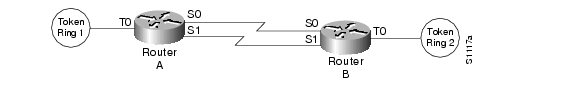
As Figure 125 shows, two routers are connected by two serial lines. Each is configured as a basic remote dual-port bridge, but extended to include both reliability and IP load sharing. When both serial lines are up, traffic is split between them, effectively combining the bandwidth of the connections. If either serial line goes down, all traffic is routed to the remaining line with no disruption. This happens transparently with respect to the end connections, unlike other source-route bridges that would abort those connections.
Figure 125 RSRB—Simple Reliability
The sample configuration files that enable this configuration follow.
Configuration for Router/Bridge A
source-bridge ring-group 5source-bridge remote-peer 5 tcp 204.31.7.1source-bridge remote-peer 5 tcp 204.31.8.1!interface tokenring 0ip address 204.31.7.1 255.255.255.0source-bridge 1 1 5source-bridge spanningmultiring all!interface serial 0ip address 204.31.9.1 255.255.255.0!interface serial 1ip address 204.31.10.1 255.255.255.0!router igrp 109network 204.31.7.0network 204.31.9.0network 204.31.10.0!hostname RouterAConfiguration for Router/Bridge B
source-bridge ring-group 5source-bridge remote-peer 5 tcp 204.31.7.1source-bridge remote-peer 5 tcp 204.31.8.1!interface tokenring 0ip address 204.31.8.1 255.255.255.0source-bridge 2 1 5source-bridge spanningmultiring all!interface serial 0ip address 204.31.9.2 255.255.255.0!interface serial 1ip address 204.31.10.2 255.255.255.0!router igrp 109network 204.31.8.0network 204.31.9.0network 204.31.10.0!hostname RouterBConfiguring Priority for Locally Terminated Token Ring Interfaces in RSRB Example
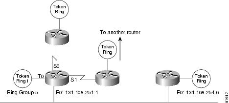
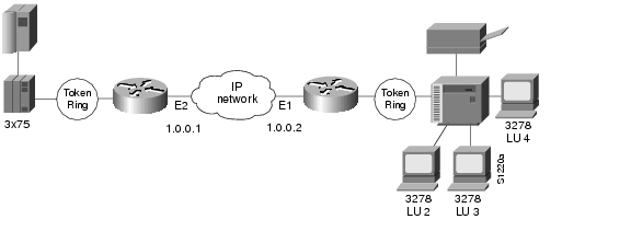
Figure 126 shows a network that uses RSRB to bridge Token Ring traffic.
Figure 126 RSRB Configuration Example
The configuration for each of the routers in Figure 126 follows.
Router/Bridge A
source-bridge ring-group 2624source-bridge remote-peer 2624 tcp 1.0.0.1source-bridge remote-peer 2624 tcp 1.0.0.2 local-ack priority!interface tokenring 0source-bridge 2576 8 2624source-bridge spanningmultiring alllocaddr-priority 1!interface ethernet 0ip address 1.0.0.1 255.255.255.0priority-group 1!locaddr-priority-list 1 02 highlocaddr-priority-list 1 03 highlocaddr-priority-list 1 04 mediumlocaddr-priority-list 1 05 low!priority-list protocol ip high tcp 1996priority-list protocol ip medium tcp 1987priority-list protocol ip normal tcp 1988priority-list protocol ip low tcp 1989Router/Bridge B
source-bridge ring-group 2624source-bridge remote-peer 2624 tcp 1.0.0.2source-bridge remote-peer 2624 tcp 1.0.0.1 local-ack priority!interface tokenring 0source-bridge 2626 8 2624source-bridge spanningmultiring alllocaddr-priority 1!interface ethernet 0ip address 1.0.0.2 255.255.255.0priority-group 1!locaddr-priority-list 1 02 highlocaddr-priority-list 1 03 highlocaddr-priority-list 1 04 mediumlocaddr-priority-list 1 05 low!priority-list protocol ip high tcp 1996priority-list protocol ip medium tcp 1987priority-list protocol ip normal tcp 1988priority-list protocol ip low tcp 1989