Analog Modem Network Modules
Available Languages
Table Of Contents
Connecting Cisco Analog Modem Network Modules to the Network
8- and 16-Port Analog Modem Network Modules
8- and 16-Port Analog Modem Network Modules, Version 2
Connecting the Modules to the Telephone Network
Analog Modem Network Module LEDs
Obtaining Documentation, Obtaining Support, and Security Guidelines
Connecting Cisco Analog Modem Network Modules to the Network
Revised: May 1, 2008, OL-12814-01
This guide describes how to connect Cisco Analog Modem network modules to your network. It contains the following sections:
•
8- and 16-Port Analog Modem Network Modules
•
8- and 16-Port Analog Modem Network Modules, Version 2
•
Connecting the Modules to the Telephone Network
•
Analog Modem Network Module LEDs
•
Obtaining Documentation, Obtaining Support, and Security Guidelines
8- and 16-Port Analog Modem Network Modules
The following analog modem network modules originate or terminate analog telephone transmissions through RJ-11 modular jacks:
•
8-port analog modem network module (NM-8AM) (see Figure 1)
•
16-port analog modem network module (NM-16AM) (see Figure 2)
Figure 1 8-Port Analog Modem Network Module

Figure 2 16-Port Analog Modem Network Module

The following warning applies in Australia:

Warning
This equipment will be inoperable when main power fails.
The following warning applies in New Zealand:

Warning
This equipment does not fully meet Telecom's impedance requirements. Performance limitations may occur when used in conjunction with some parts of the network. Telecom will accept no responsibility should difficulties arise in such circumstances.
Network Protocols Supported
The analog modems described in this chapter support the following protocols:
•
All standard data rates from 300 bps to 33.6 kbps (V.34bis)
•
V.42bis and Microcom Network Protocol (MNP) 5 data compression
•
V.42, Link Access Procedure for Modems (LAPM), and MNP 2 to 4 error correction
•
MNP 10 for high performance under all line conditions
•
MNP 10EC for high performance in analog cellular environments
8- and 16-Port Analog Modem Network Modules, Version 2
The following analog modem network modules originate or terminate analog telephone transmissions through RJ-11 modular jacks:
•
8-port analog modem network module (NM-8AM-V2) (see Figure 3)
•
16-port analog modem network module (NM-16AM-V2) (see Figure 4)

CautionTo comply with the Telcordia GR-1089 NEBS standard for electromagnetic compatibility and safety, connect the 16-port analog modem network module (NM-16AM-V2) only to intra-building or non-exposed wiring or cabling. The intrabuilding cable must be shielded and the shield must be grounded at both ends.
Figure 3 8-Port Analog Modem Network Module (NM-8AM-V2)

Figure 4 16-Port Analog Modem Network Module (NM-16AM-V2)

The following warning applies in Australia:

Warning
This equipment will be inoperable when main power fails.
The following warning applies in New Zealand:

Warning
This equipment does not fully meet Telecom's impedance requirements. Performance limitations may occur when used in conjunction with some parts of the network. Telecom will accept no responsibility should difficulties arise in such circumstances.
Network Protocols Supported
The analog modems described in this chapter support these protocols:
•
Standardized modem protocols
–
ITU-T V.90
–
V.92 Quick Connect
–
ITU-T V.34bis
–
ITU-T V.34
–
ITU-T V.34+ up to 33,600 bps
–
ITU-T V.32bis
–
ITU-T V.32
–
ITU-T V.32 turbo up to 19,200 bps
–
ITU-T V.22bis (with V.54 loopback)
–
ITU-T V.22 A/B
–
ITU-T V.23 at 75 and 1200 bps
–
ITU-T V.21 at 300 bps
–
BELL 103 and 212a
•
Standardized fax protocols
–
ITU-T V.17
–
ITU-T V.29
–
ITU-T V.27ter
–
ITU-T V.21 channel 2
–
EIA 578 Class 2
–
Group 3 fax class 1 and class 2
•
Standardized modem error correction and compression
–
MNP 2 - 4
–
ITU-T V.42 Link Access Procedure for Modems (LAPM)
–
Microcom Network Protocol (MNP) 5
–
V.42bis (with 4-K dictionaries)
–
ITU-T V.44
Interface Numbering
Cisco IOS software identifies each modem uniquely by its slot number and port number.
Some Cisco IOS configuration commands identify asynchronous ports by an interface number (or a line number, which is the same as the interface number). The interface number of a port on an 8- or 16-port analog modem network module is related to the slot number where the module is installed and the number of the port in the module.
Ports in the 8- and 16-port analog modem network modules are numbered in the same pattern as slot numbers, beginning at 0 at the lower right and continuing from right to left and (in the 16-port module) from bottom to top.
The interface number of a port is determined in the following way:
interface-number = (32 x slot-number) + port-number + 1
For example, modem port 12 in slot 1 corresponds to interface number (32 x 1) + 12 + 1 = 45. This is also the line number for the port. Port 12 in slot 1 is always assigned interface number 45, regardless of whether the module in slot 0 is an 8-port analog modem network module, a 16-port analog modem module, or some other kind of module entirely, or even whether there is a network module in slot 0 at all. If you move the module from slot 1 to a different slot, however, its interface numbers change.
Table 1 shows the range of interface numbers available for each type of analog modem network module in each router slot. (Interface 0 is automatically assigned to the console.)
Connecting the Modules to the Telephone Network
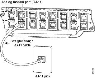
Each analog modem network module provides 8 or 16 RJ-11 jacks for standard modular cables. These ports are color-coded pink. Cables are not provided with the network module.
To establish an analog connection, use a straight-through RJ-11 modular cable to connect the jack to a wall telephone outlet. (See Figure 5.)
Figure 5 Connecting an Analog Modem Network Module

Analog Modem Network Module LEDs
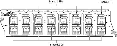
All network modules have an enable (EN) LED. This LED indicates that the module has passed its self-tests and is available.
Each modem in the module has an in use (IN USE) LED that lights when the modem is off-hook. (See Figure 6 and Figure 7.)
Figure 6 8-Port Analog Modem Network Module LEDs

Figure 7 16-Port Analog Modem Network Module LEDs

Related Documents
For additional information, see the following documents and resources.
Regulatory compliance and safety information
Cisco Network Modules and Interface Cards Regulatory Compliance and Safety Information
http://www.cisco.com/en/US/docs/routers/access/interfaces/rcsi/IOHrcsi.htmlCisco IOS software website and reference documentation
Cisco IOS Software
http://www.cisco.com/web/psa/products/index.html?c=268438303
Obtaining Documentation, Obtaining Support, and Security Guidelines
For information on obtaining documentation, obtaining support, providing documentation feedback, security guidelines, and also recommended aliases and general Cisco documents, see the monthly What's New in Cisco Product Documentation, which also lists all new and revised Cisco technical documentation, at:
http://www.cisco.com/en/US/docs/general/whatsnew/whatsnew.html
CCDE, CCENT, Cisco Eos, Cisco Lumin, Cisco StadiumVision, the Cisco logo, DCE, and Welcome to the Human Network are trademarks; Changing the Way We Work, Live, Play, and Learn is a service mark; and Access Registrar, Aironet, AsyncOS, Bringing the Meeting To You, Catalyst, CCDA, CCDP, CCIE, CCIP, CCNA, CCNP, CCSP, CCVP, Cisco, the Cisco Certified Internetwork Expert logo, Cisco IOS, Cisco Press, Cisco Systems, Cisco Systems Capital, the Cisco Systems logo, Cisco Unity, Collaboration Without Limitation, EtherFast, EtherSwitch, Event Center, Fast Step, Follow Me Browsing, FormShare, GigaDrive, HomeLink, Internet Quotient, IOS, iPhone, iQ Expertise, the iQ logo, iQ Net Readiness Scorecard, iQuick Study, IronPort, the IronPort logo, LightStream, Linksys, MediaTone, MeetingPlace, MGX, Networkers, Networking Academy, Network Registrar, PCNow, PIX, PowerPanels, ProConnect, ScriptShare, SenderBase, SMARTnet, Spectrum Expert, StackWise, The Fastest Way to Increase Your Internet Quotient, TransPath, WebEx, and the WebEx logo are registered trademarks of Cisco Systems, Inc. and/or its affiliates in the United States and certain other countries.
All other trademarks mentioned in this document or Website are the property of their respective owners. The use of the word partner does not imply a partnership relationship between Cisco and any other company. (0804R)
Any Internet Protocol (IP) addresses used in this document are not intended to be actual addresses. Any examples, command display output, and figures included in the document are shown for illustrative purposes only. Any use of actual IP addresses in illustrative content is unintentional and coincidental.
© 2008 Cisco Systems, Inc. All rights reserved.
Contact Cisco
- Open a Support Case

- (Requires a Cisco Service Contract)
 Feedback