Ethernet, Fast Ethernet, and Token Ring Network Modules
Available Languages
Table Of Contents
Connecting Cisco Ethernet, Fast Ethernet, and Token Ring Network Modules to the Network
1- and 4-Port Ethernet Modules
Ethernet 2-WAN Card Slot Modules
Fast Ethernet 2-WAN Card Slot Modules
Connecting Fast Ethernet Ports
Obtaining Documentation, Obtaining Support, and Security Guidelines
Connecting Cisco Ethernet, Fast Ethernet, and Token Ring Network Modules to the Network
Revised: 08/07/2008, OL-12807-01
This guide describes how to connect Cisco Ethernet, Fast Ethernet, and Token Ring network modules to your network. It contains the following sections:
•
Fast Ethernet Network Modules
•
Obtaining Documentation, Obtaining Support, and Security Guidelines
Ethernet Network Modules
Ethernet connections are provided on 1- and 4-port Ethernet modules, and on 1-port Ethernet, 2-port Ethernet, and 1-port Ethernet 1-port Token Ring 2-WAN card slot modules.
1- and 4-Port Ethernet Modules
The following network modules provide Ethernet interfaces:
•
1-port Ethernet network module (NM-1E) (see Figure 1)
•
4-port Ethernet network module (NM-4E) (see Figure 2)
Figure 1 1-Port Ethernet Network Module

Figure 2 4-Port Ethernet Network Module

Ethernet 2-WAN Card Slot Modules
The following 2-slot network modules provide one or two Ethernet interfaces, plus two slots for optional WAN interface cards:
•
1-Ethernet 2-WAN card slot network module (NM-1E2W) (see Figure 3)
•
2-Ethernet 2-WAN card slot network module (NM-2E2W) (see Figure 4)
•
1-Ethernet 1-Token Ring 2-WAN card slot network module (NM-1E1R2W) (see Figure 5)
Figure 3 1-Ethernet 2-WAN Card Slot Network Module

Figure 4 2-Ethernet 2-WAN Card Slot Network Module

Figure 5 1-Ethernet 1-Token Ring 2-WAN Card Slot Network Module
Ethernet Connectors
The 1-port Ethernet network module, the 1-Ethernet 2-slot network module, and the 1-Ethernet 1-Token Ring 2-slot network module each provide a single Ethernet port. This port uses either the attachment unit interface (AUI) DB-15 connector on the right side of the module or the 10BASE-T (RJ-45) connector next to it. Only one of these connectors can be active at a time. The active port is identified in software by port type (Ethernet), slot number on the module, and port number 0.
All modules detect the type of network connection automatically, and you do not need to choose the media type in software. If cables are plugged into both ports, the 10BASE-T connection is chosen.
The 4-port Ethernet network module has ports for four Ethernet connections (0, 1, 2, and 3). Port 0 offers a choice of an AUI or 10BASE-T interface. Ethernet ports 1, 2, and 3 use 10BASE-T connectors only. These ports do not provide an AUI connector.
The 2-Ethernet 2-slot network module has ports for two Ethernet connections. Port 0 offers a choice of AUI or 10BASE-T. Port 1 uses 10BASE-T only.
Connecting Ethernet Ports
If an Ethernet port offers both an AUI connector and a 10BASE-T connector, you can use either connector, but not both at the same time.
AUI Connections
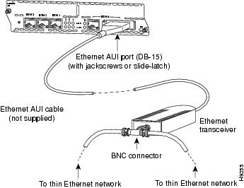
Use an Ethernet AUI cable to connect an AUI port to an Ethernet transceiver. These ports are color-coded yellow. The female end of the AUI cable mates with the slide-latch connector of the transceiver cable. Figure 6 shows a thin Ethernet transceiver as an example, but you can use any type of Ethernet transceiver.
If the transceiver cable has thumbscrew connectors, you can connect it directly to the AUI port by replacing the AUI port slide latch with a jackscrew (provided in a separate bag).
Figure 6 Connecting an Ethernet AUI Port to a Transceiver
10BASE-T Connections
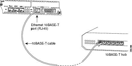
Use an Ethernet 10BASE-T cable to connect a 10BASE-T port to a hub or other network device. These ports are color-coded yellow. Figure 7 shows the 10BASE-T port on an Ethernet network module connected to a hub.
Figure 7 Connecting an Ethernet 10BASE-T Port to a Hub
Ethernet LEDs
This section describes Ethernet module LEDs. Figure 8 shows 4-port Ethernet network module LEDs as an example.
All network modules have an enable (EN) LED. This LED indicates that the module has passed its self-tests and is available to the router.
Each Ethernet port has two LEDs. The activity (ACT) LED indicates that the router is sending or receiving Ethernet transmissions. The link (LINK) LED indicates that the Ethernet port is receiving the link integrity signal from the hub (10BASE-T only).
Figure 8 Ethernet Network Module LEDs (Typical)

Fast Ethernet Network Modules
Fast Ethernet connections are provided on 1-port Fast Ethernet modules, and on 1-port Fast Ethernet, 2-port Fast Ethernet, and 1-port Fast Ethernet 1-port Token Ring 2-WAN card slot modules.
1-Port Fast Ethernet Modules
The following network modules provide Fast Ethernet interfaces:
•
1-port Fast Ethernet network module with TX connector, Cisco product number NM-1FE-TX. (See Figure 9.) This module provides an RJ-45 connector for direct connection to 100BASE-T Ethernet networks.
•
1-port Fast Ethernet network module with FX connector, Cisco product number NM-1FE-FX. (See Figure 10.) This module provides a duplex SC-type fiber-optic port for direct connection to 100BASE-FX Ethernet networks.
Figure 9 1-Port Fast Ethernet Network Module (TX Connector)

Figure 10 1-Port Fast Ethernet Network Module (FX Connector)

Fast Ethernet 2-WAN Card Slot Modules
The following 2-slot network modules provide one or two 100BASE-T Fast Ethernet interfaces, plus two slots for optional WAN interface cards:
•
1-Fast Ethernet 2-WAN card slot network module (NM-1FE2W and NM-1FE2W-V2). See Figure 11 for a sample faceplate.
•
2-Fast Ethernet 2-WAN card slot network module (NM-2FE2W and NM-2FE2W-V2). See Figure 12 for a sample faceplate.
•
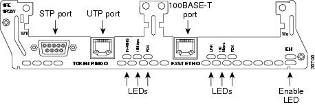
1-Fast Ethernet 1-Token Ring 2-WAN card slot network module (NM-1FE1R2W and NM-1FE1R2W-V2). See Figure 13 for a sample faceplate.

CautionTo comply with the Telcordia GR-1089 NEBS standard for electromagnetic compatibility and safety, connect the 1-Fast Ethernet 2-WAN card slot network modules (NM-1FE2W-V2, NM-1FE2W), the 2-Fast Ethernet 2-WAN card slot network modules (NM-2FE2W-V2, NM-2FE2W), the 2 WAN Card Slot Network Module (NM-2W)and the 1-Fast Ethernet 1-Token Ring 2-WAN card slot network modules (NM-1FE1R2W) only to intrabuilding or nonexposed wiring or cabling. The intrabuilding cable must be shielded and the shield must be grounded at both ends. The intra-building port(s) of the equipment or subassembly must not be metallically connected to interfaces that connect to the OSP or its wiring. These interfaces are designed for use as intra-building interfaces only (Type 2 or Type 4 ports as described in GR-1089-CORE, Issue 4) and require isolation from the exposed OSP cabling. The addition of Primary Protectors is not sufficient protection in order to connect these interfaces metallically to OSP wiring.
Figure 11 1-Fast Ethernet 2-WAN Card Slot Network Module
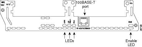
Figure 12 2-Fast Ethernet 2-WAN Card Slot Network Module
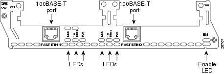
Figure 13 1-Fast Ethernet 1-Token Ring 2-WAN Card Slot Network Module
Connecting Fast Ethernet Ports
Use the following sections for 100BASE-T or 100BASE-FX connections.
100BASE-T Connections
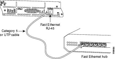
Use a two-pair Category 5 or unshielded twisted-pair (UTP) straight-through RJ-45 cable to connect a Fast Ethernet RJ-45 port to a switch, hub, repeater, server, or other network device. Figure 14 shows an RJ-45 port connected to a hub.

Note
RJ-45 cables are not available from Cisco Systems. These cables are widely available and must be Category 5 cables.
Figure 14 Connecting a Fast Ethernet RJ-45 Port to a Hub
100BASE-FX Connections
Attach a multimode fiber-optic cable with SC-type connectors directly to the port on the Fast Ethernet network module (remove the protective plug from the port if it is present). Use either one duplex SC connector (see Figure 15 and Figure 17) or two simplex SC connectors (see Figure 16 and Figure 18). Attach the other end of the cable to a repeater, hub, or wall outlet. Be sure to observe the correct relationship between the receive (RX) and transmit (TX) ports on the network module and the cable.

Note
Multimode SC-type fiber-optic cables are widely available commercially. Cisco Systems does not supply these cables.
Figure 15 Duplex SC Connector

Figure 16 Simplex SC Connector

Figure 17 Connecting a Fast Ethernet FX Port to a Repeater or Hub (Duplex Connector)
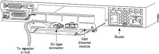
Figure 18 Connecting a Fast Ethernet FX Port to a Repeater or Hub (Simplex Connectors)

Fast Ethernet LEDs
This section describes Fast Ethernet module LEDs. Figure 19 shows 1-port Fast Ethernet network module LEDs as an example.
Figure 19 1-Port Fast Ethernet Network Module LEDs

All network modules have an enable (EN) LED. The enable LED indicates that the module has passed its self-tests and is available to the router.
Fast Ethernet network modules have the additional LEDs shown in Table 1.
Token Ring Network Modules
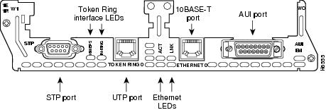
The following network modules provide Token Ring interfaces:
•
1-port Ethernet 1-port Token Ring 2-WAN card slot module (NM-1E1R2W) (see Figure 20)
•
1-port Fast Ethernet 1-port Token Ring 2-WAN card slot module (NM-1FE2R2W) (see Figure 21)
Figure 20 1-Ethernet 1-Token Ring 2-WAN Card Slot Network Module

Figure 21 1-Fast Ethernet 1-Token Ring 2-WAN Card Slot Network Module

Connecting Token Ring Ports
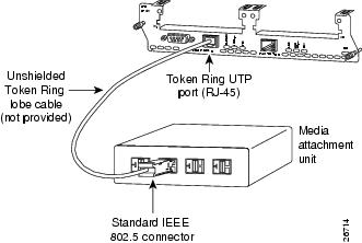
The 1-Ethernet 1-Token Ring 2-WAN card slot network module and the 1-Fast Ethernet 1-Token Ring 2-WAN card slot network module each have one DB-9 connector for an STP Token Ring connection and one RJ-45 connector for a UTP Token Ring connection. Only one connector can be active at a time.
To connect the module to a Token Ring network, attach one end of a shielded Token Ring lobe cable to the DB-9 connector on the network module (see Figure 22), or attach one end of an unshielded Token Ring lobe cable to the UTP connector on the network module (see Figure 23). Attach the other end of the cable to the Token Ring media attachment unit (MAU). The network module automatically detects which connector is in use.
Figure 22 Connecting a Token Ring STP Port (DB-9) to a MAU
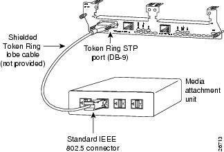
Figure 23 Connecting a Token Ring UTP Port (RJ-45) to an MAU
Token Ring LEDs
All network modules have an enable (EN) LED. The enable LED indicates that the module has passed its self-tests and is available to the router.
The 1-Ethernet 1-Token Ring 2-WAN card slot network module and the 1-Fast Ethernet 1-Token Ring 2-WAN card slot network module both have the following Token Ring LEDs:
•
The 16MBPS LED indicates a ring speed of 16 Mbps. If it is off, the ring speed is 4 Mbps.
•
The IN-RING LED indicates that the Token Ring interface is inserted into the ring. If it is off, the interface is not inserted into the ring.
The 1-Fast Ethernet 1-Token Ring 2-slot network module also has the FDX LED, which indicates full-duplex mode.

Timesaver
When the IN-RING LED is off, you can unplug the Token Ring cable without causing a problem on the ring.
Related Documents
For additional information, see the following documents and resources.
Regulatory compliance and safety information
Cisco Network Modules and Interface Cards Regulatory Compliance and Safety Information
http://www.cisco.com/en/US/docs/routers/access/interfaces/rcsi/IOHrcsi.htmlCisco IOS software website and reference documentation
Cisco IOS Software http://www.cisco.com/web/psa/products/index.html?c=268438303
Obtaining Documentation, Obtaining Support, and Security Guidelines
For information on obtaining documentation, obtaining support, providing documentation feedback, security guidelines, and also recommended aliases and general Cisco documents, see the monthly What's New in Cisco Product Documentation, which also lists all new and revised Cisco technical documentation, at:
http://www.cisco.com/en/US/docs/general/whatsnew/whatsnew.html
CCDE, CCENT, Cisco Eos, Cisco Lumin, Cisco Nexus, Cisco StadiumVision, Cisco TelePresence, the Cisco logo, DCE, and Welcome to the Human Network are trademarks; Changing the Way We Work, Live, Play, and Learn and Cisco Store are service marks; and Access Registrar, Aironet, AsyncOS, Bringing the Meeting To You, Catalyst, CCDA, CCDP, CCIE, CCIP, CCNA, CCNP, CCSP, CCVP, Cisco, the Cisco Certified Internetwork Expert logo, Cisco IOS, Cisco Press, Cisco Systems, Cisco Systems Capital, the Cisco Systems logo, Cisco Unity, Collaboration Without Limitation, EtherFast, EtherSwitch, Event Center, Fast Step, Follow Me Browsing, FormShare, GigaDrive, HomeLink, Internet Quotient, IOS, iPhone, iQ Expertise, the iQ logo, iQ Net Readiness Scorecard, iQuick Study, IronPort, the IronPort logo, LightStream, Linksys, MediaTone, MeetingPlace, MeetingPlace Chime Sound, MGX, Networkers, Networking Academy, Network Registrar, PCNow, PIX, PowerPanels, ProConnect, ScriptShare, SenderBase, SMARTnet, Spectrum Expert, StackWise, The Fastest Way to Increase Your Internet Quotient, TransPath, WebEx, and the WebEx logo are registered trademarks of Cisco Systems, Inc. and/or its affiliates in the United States and certain other countries.
All other trademarks mentioned in this document or Website are the property of their respective owners. The use of the word partner does not imply a partnership relationship between Cisco and any other company. (0807R)
Any Internet Protocol (IP) addresses used in this document are not intended to be actual addresses. Any examples, command display output, and figures included in the document are shown for illustrative purposes only. Any use of actual IP addresses in illustrative content is unintentional and coincidental.
© 2008 Cisco Systems, Inc. All rights reserved.
Contact Cisco
- Open a Support Case

- (Requires a Cisco Service Contract)
 Feedback