Digital Modem Network Modules
Available Languages
Table Of Contents
Connecting Cisco Digital Modem Network Modules to the Network
Digital Modem Network Modules Overview
Hardware and Software Requirements
Adding 6-Port MICA Modules to a Digital Modem Network Module
Removing the Digital Modem Network Module
Installing 6-Port MICA Modules
Reinstalling the Digital Modem Network Module
Obtaining Documentation, Obtaining Support, and Security Guidelines
Connecting Cisco Digital Modem Network Modules to the Network
Revised: May 1, 2008, OL-12813-01
This guide describes how to connect Cisco digital modem network modules to your network. It contains the following sections:
•
Digital Modem Network Modules Overview
•
Adding 6-Port MICA Modules to a Digital Modem Network Module
•
Obtaining Documentation, Obtaining Support, and Security Guidelines
Digital Modem Network Modules Overview
These modules (see Figure 1) contain 6, 12, 18, 24, or 30 V.34+ digital modems for a direct digital connection to an Integrated Services Digital Network (ISDN) Primary Rate Interface (PRI) or Basic Rate Interface (BRI) channel, allowing you to mix digital and analog calls to provide remote access to a LAN.
Figure 1 Digital Modem Network Module

Digital modem network modules do not provide network interfaces of their own, but instead handle analog calls passing through other router interfaces. In addition to the digital modem module, the router must contain a PRI or BRI interface to connect to the ISDN channel, and another interface, such as Ethernet, to provide connectivity to the LAN. The PRI or BRI module concurrently handles digital ISDN data connections and remote voice-channel (analog) modem connections, allowing a dynamic mix of digital and modem connections. The digital modem module acts as a pool of available modems that can be used for both incoming and outgoing calls.
The digital modems support all standard data rates from 300 bps through 33.6 kbps (V.34 bis); V.42 bis and MNP 5 data compression; and V.42, LAPM, and MNP 4 error correction.
Each digital modem module contains from one to five banks of 6-port modem ISDN channel aggregation (MICA) modules. You can add modems to a module, in groups of six, by installing additional MICA modules (Cisco product number MICA-6MOD), up to a maximum of 30 modems.
Hardware and Software Requirements
In addition to the digital modem module, the router must contain a PRI or BRI network interface to connect to the ISDN channel, and another interface, such as Ethernet or Fast Ethernet, to provide connectivity to the LAN.
A PRI network module (NM-1CT1, NM-2CT1, NM-1CT1-CSU, NM-2CT1-CSU, NM-1CE1B, NM-2CE1B, NM-1CE1U, or NM-2CE1U) used with a digital modem module must be revision level -03 or higher. A BRI S/T network module (NM-4B-S/T or NM-8B-S/T) must be revision level -03 or higher, and a BRI U module (NM-4B-U or NM-8B-U) must be revision level -06 or higher. Earlier revisions of these network modules cannot send modem calls to the digital modem module.
If the PRI or BRI module is the wrong revision, you see a message similar to this one when the router boots:
The T1 or E1 network module in slot 0 is incompatible with the digital modems installed in
the router.
To determine the revision level, you can examine the network module itself (outside the router), or use the Cisco IOS show diag command. The label on the module board should show a part number beginning with 800- and ending with the revision level. The output of the show diag command looks similar to the following:
Slot 3:Port adapter is analyzedPort adapter insertion time unknownHardware revision 1.0 Board revision A0Serial number 4152626 Part number 800-01228-01Test history 0x0 RMA number 00-00-00EEPROM format version 1EEPROM contents (hex):0x20: 01 26 01 00 00 3F 5D 32 50 04 CC 01 00 00 00 000x30: 50 00 00 00 96 11 04 17 FF FF FF FF FF FF FF FFInterface Numbering
Individual digital modem ports are not physically distinct, but Cisco IOS software identifies each modem uniquely through its slot number and port number.
Each digital modem module can hold up to five banks of MICA modules, numbered 0 to 4 from left to right (as viewed from the rear of the router). Each MICA module holds six modems, which are assigned modem numbers 0 to 5.
Each modem in a digital modem module is also assigned a port number in the range 0 to 29. Modems in the left MICA module (as viewed from the rear of the router), bank 0, are assigned port numbers 0 to 5. Additional MICA modules, if present, are assigned port numbers as follows:
port-number = (6 x bank-number) + modem-number
For example, the third modem (modem 2) in the second MICA module from the left (bank 1) is assigned port number (6 x 1) + 2 = 8.
Some Cisco IOS commands identify ports by interface number (or line number or TTY number, which is the same as the interface number) rather than slot and port number. The interface number of a modem port is related to its slot and port number in the following way:
interface-number = (32 x slot-number) + port-number + 1
This can also be expressed as:
interface-number = (32 x slot-number) + ((6 x bank-number) + modem-number) + 1
For example, if the module containing the modem in the last example is placed in slot 2, the modem is assigned interface number (32 x 2) + ((6 x 1) + 2) + 1 = (32 x 2) + 8 + 1 = 73. This is also the line and TTY number for the port. The modem in this position is always assigned interface 73, whether or not there are other MICA modules in the digital modem network module or other digital modem network modules in the router chassis. If you move the MICA module to a different position in the digital modem network module, however, or move the digital modem network module to a different slot in the router chassis, the interface number changes.
Table 1 shows the range of interface numbers available in each router slot. Interface 0 is automatically assigned to the console.
Table 1 Digital Modem Network Module Interface Numbering
0
1-30
1
33-62
2
65-94
3
97-126
4
129-158
5
161-190
6
193-222
Adding 6-Port MICA Modules to a Digital Modem Network Module
You can add modems to a digital modem network module, in groups of six, by installing additional 6-port MICA modules, up to a maximum of five MICA modules (30 modems).
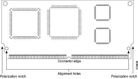
MICA modules are manufactured with a polarization notch to ensure proper orientation, and alignment holes that fit over guide posts to ensure proper positioning. (See Figure 2.)
Figure 2 6-Port MICA Module

CautionTo avoid damaging electrostatic discharge (ESD)-sensitive components, observe all ESD precautions when handling MICA modules. To avoid damaging the network module or the MICA module, avoid excessive force when you remove or replace MICA modules.
To remove, replace, or install a MICA module, you must first remove the digital modem module from the router chassis.
Removing the Digital Modem Network Module

CautionDigital modem network modules do not currently support online insertion and removal (hot swap) of network modules. To avoid damaging the module, you must turn off electrical power and disconnect network cables before you remove it from the chassis slot.
To remove a digital modem network module, follow these steps:
Step 1
Turn off electrical power to the router. However, to channel ESD voltages to ground, do not unplug the power cable. Remove all network interface cables, including telephone cables, from the rear panel.
The following warning applies to routers that use a DC power supply:

Warning
Before performing any of the following procedures, ensure that power is removed from the DC circuit. To ensure that all power is OFF, locate the circuit breaker on the panel board that services the DC circuit, switch the circuit breaker to the OFF position, and tape the switch handle of the circuit breaker in the OFF position. Statement 7
Step 2
Loosen the modules captive mounting screws, using a Phillips or flat-blade screwdriver.
Step 3
Hold the captive screws between two fingers, and pull the network module toward you until it slides free of the chassis. (See Figure 3.)
Step 4
Set the network module on an ESD-preventive mat.
Figure 3 Removing a Digital Modem Network Module from a Router

Removing 6-Port MICA Modules
To remove a MICA module from the digital modem network module, follow these steps:
Step 1
Orient the digital modem network module so that the faceplate is on the right.

CautionHandle MICA modules by the card edges only. MICA modules are ESD-sensitive components and can be damaged by mishandling.
Step 2
Remove one MICA module at a time, beginning with the one farthest from you.
Step 3
To lift the MICA module out of its socket, pull the spring clips on both sides outward (see Figure 4) and tilt the MICA module away from you until it is free of the clips (see Figure 5).
Step 4
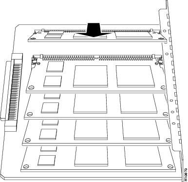
Hold the MICA module by the edges with your thumb and index finger and lift it out of the socket (see Figure 6). Place the removed MICA module in an antistatic bag to protect it from ESD damage.
Step 5
Repeat Step 2 through Step 4 for any remaining MICA modules that you want to remove.
Figure 4 Releasing the Mounting Clips
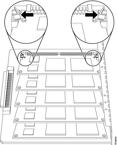
Figure 5 Tilting a 6-Port MICA Module Free of the Mounting Clips
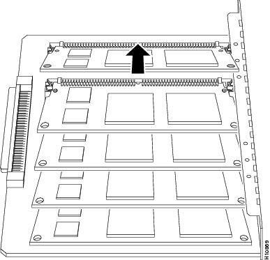
Figure 6 Lifting a 6-Port MICA Module Out of the Socket
Installing 6-Port MICA Modules
To install new or replacement MICA modules, follow these steps:
Step 1
Orient the digital modem network module so that the faceplate is on the right.

CautionHandle MICA modules by the card edges only. MICA modules are ESD-sensitive components and can be damaged by mishandling.
Step 2
Hold the MICA module with the connector edge at the bottom and the polarization notch at the right.
Step 3
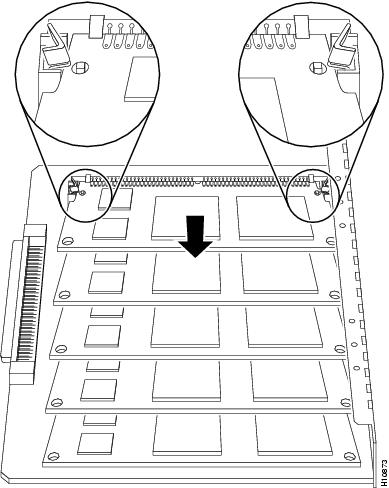
Tilting the MICA module toward you at about a 45-degree angle, insert it into a socket, beginning with the empty socket closest to you. (See Figure 7.) Rock it downward, using the minimum amount of force required. (See Figure 8.) When the MICA module is properly seated, the socket guide posts fit through the alignment holes, and the spring clips click into place.
Step 4
Ensure that the MICA module is straight and that the alignment holes line up with the plastic guides on the socket. It is normal to feel some resistance, but do not use excessive force on the MICA module, and do not touch the surface components.
Step 5
Repeat Step 2 through Step 4 for any additional MICA modules.
Figure 7 Inserting a 6-Port MICA Module into a Socket
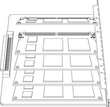
Figure 8 Rocking a 6-Port MICA Module Downward
Reinstalling the Digital Modem Network Module
When you finish installing MICA modules, replace the digital modem network module in the router chassis, following these steps:
Step 1
Align the network module with the guides in the chassis and slide it gently into the slot.
Step 2
Push the module into place until you feel its edge connector mate securely with the connector on the motherboard.
Step 3
Fasten the module captive mounting screws into the holes in the chassis, using the Phillips or flat-blade screwdriver.
Step 4
If the router was previously running, reinstall the network interface cables and turn on power to the router.
The following warning applies to routers that use a DC power supply:

Warning
After wiring the DC power supply, remove the tape from the circuit breaker switch handle and reinstate power by moving the handle of the circuit breaker to the ON position. Statement 8
Digital Modem Module LEDs
All network modules have an enable (EN) LED. (See Figure 9.) This LED indicates that the module has passed its self-tests and is available to the router.
Digital modem modules have five additional LEDs, one for each MICA module bank. The LEDs blink during initialization. After the enable LED comes on, the MICA module LEDs indicate that the corresponding MICA module is functioning. If a MICA module fails its diagnostics, or if no MICA module is installed in a position, its LED remains off.
Figure 9 Digital Modem Network Module LEDs

Related Documents
For additional information, see the following documents and resources.
Regulatory compliance and safety information
Cisco Network Modules and Interface Cards Regulatory Compliance and Safety Information
http://www.cisco.com/en/US/docs/routers/access/interfaces/rcsi/IOHrcsi.htmlCisco IOS software website and reference documentation
Cisco IOS Software http://www.cisco.com/web/psa/products/index.html?c=268438303
Obtaining Documentation, Obtaining Support, and Security Guidelines
For information on obtaining documentation, obtaining support, providing documentation feedback, security guidelines, and also recommended aliases and general Cisco documents, see the monthly What's New in Cisco Product Documentation, which also lists all new and revised Cisco technical documentation, at:
http://www.cisco.com/en/US/docs/general/whatsnew/whatsnew.html
CCDE, CCENT, Cisco Eos, Cisco Lumin, Cisco StadiumVision, the Cisco logo, DCE, and Welcome to the Human Network are trademarks; Changing the Way We Work, Live, Play, and Learn is a service mark; and Access Registrar, Aironet, AsyncOS, Bringing the Meeting To You, Catalyst, CCDA, CCDP, CCIE, CCIP, CCNA, CCNP, CCSP, CCVP, Cisco, the Cisco Certified Internetwork Expert logo, Cisco IOS, Cisco Press, Cisco Systems, Cisco Systems Capital, the Cisco Systems logo, Cisco Unity, Collaboration Without Limitation, EtherFast, EtherSwitch, Event Center, Fast Step, Follow Me Browsing, FormShare, GigaDrive, HomeLink, Internet Quotient, IOS, iPhone, iQ Expertise, the iQ logo, iQ Net Readiness Scorecard, iQuick Study, IronPort, the IronPort logo, LightStream, Linksys, MediaTone, MeetingPlace, MGX, Networkers, Networking Academy, Network Registrar, PCNow, PIX, PowerPanels, ProConnect, ScriptShare, SenderBase, SMARTnet, Spectrum Expert, StackWise, The Fastest Way to Increase Your Internet Quotient, TransPath, WebEx, and the WebEx logo are registered trademarks of Cisco Systems, Inc. and/or its affiliates in the United States and certain other countries.
All other trademarks mentioned in this document or Website are the property of their respective owners. The use of the word partner does not imply a partnership relationship between Cisco and any other company. (0804R)
Any Internet Protocol (IP) addresses used in this document are not intended to be actual addresses. Any examples, command display output, and figures included in the document are shown for illustrative purposes only. Any use of actual IP addresses in illustrative content is unintentional and coincidental.
© 2008 Cisco Systems, Inc. All rights reserved.
Contact Cisco
- Open a Support Case

- (Requires a Cisco Service Contract)
 Feedback