High-Density Analog Telephony Network Modules
Available Languages
Table Of Contents
Connecting Cisco High-Density Analog Telephony Network Modules to the Network
High-Density Analog Telephony Network Module
Connecting the High-Density Analog Telephony Network Module to the Network
High-Density Analog Telephony Network Module LEDs
High-Density Analog Voice Card Pinouts
Obtaining Documentation, Obtaining Support, and Security Guidelines
Connecting Cisco High-Density Analog Telephony Network Modules to the Network
Revised: October 21, 2009, OL-12820-01
This guide describes how to connect Cisco high-density analog telephony network modules to your network. It contains the following sections:
•
High-Density Analog Telephony Network Module
•
Connecting the High-Density Analog Telephony Network Module to the Network
•
Adding Port Expansion Modules
•
High-Density Analog Telephony Network Module LEDs
•
High-Density Analog Voice Card Pinouts
•
Obtaining Documentation, Obtaining Support, and Security Guidelines
High-Density Analog Telephony Network Module
The high-density analog telephony network module is a modular, high-density voice network module that provides dual tone multifrequency (DTMF) detection, voice compression and decompression, call progress tone generation, voice activity detection (VAD), echo cancellation, and adaptive jitter buffering.
The high-density analog telephony network module supports two different expansion modules, providing up to 12 ports in addition to the 4 Foreign Exchange Service (FXS) ports on the base high-density analog telephony network module (NM-HDA). See Table 1 for expansion module support information.
Table 1 Expansion Modules Supported on the Cisco High-Density Analog Telephony Network Module (NM-HDA)
EM-HDA-8FXS
FXS
8
EM3-HDA-8FXS
FXS
8
EM-HDA-4FXO
FXO1
4
EM2-HDA-4FXO
FXO
4
1 FXO = Foreign Exchange Office
These expansion modules can be used in the following combinations:
•
12 Foreign Exchange Station (FXS) ports (NM-HDA with installed EM-HDA-8FXS and EM3-HDA-8FXS expansion modules)
•
Eight Foreign Exchange Office (FXO) ports and four FXS ports (NM-HDA with two installed EM-HDA-4FXO or EM2-HDA-4FXO expansion modules)
•
12 FXS and four FXO ports (NM-HDA with installed EM-HDA-8FXS, EM3-HDA-8FXS, and EM-HDA-4FXO or EM2-HDA-4FXO expansion modules)
The FXO expansion module supports a power failure port that connects directly to the central office (CO) in case of failure. Physical ports are added as shown in Table 2.

Tip
To maintain an emergency connection during power outages, connect port 14 or port 24 to the public switched telephone network (PSTN). Phones connected to port 8 or port 18 fail over to the PSTN connections through port 14 or port 24 during power outages.

Note
If you have specified the use of a private line automatic ringdown (PLAR) off-premises extension (OPX) connection mode for an FXO voice port (with loop resistance less than 8000 Ohm), you must ensure that the soft-offhook option is enabled on the port.
This option allows a stepped offhook resistance during seizure which avoids overloading the circuit during offhook in the event that ringing voltage is present on the circuit at the same time as the trunk seizure. The stepped offhook resistance is initially set to 800 Ohms, then adjusts to 50 Ohms when ringing voltage is not present.
To enable soft-offhook command on the port, and to access the connection command with plar opx syntax, see the Cisco Command Lookup Tool.
The digital signal processors (DSPs) on the card support up to 8 ports of high-complexity codecs or up to 16 ports of medium- and low-complexity codecs. The number of DSPs must be increased if more than eight ports of high-complexity codecs are needed. In this case, a DSP expansion module must be installed.
The high-density analog telephony network module is connected to the network using an RJ-21 Amphenol connector on the front panel. The front of the card is shown in Figure 1.
Figure 1 High-Density Analog Telephony Network Module

Connecting the High-Density Analog Telephony Network Module to the Network
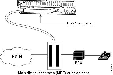
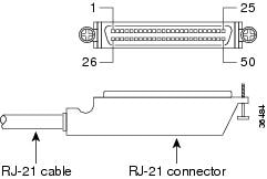
The high-density analog telephony network module is connected to a distribution frame with an RJ-21 cable. (See Figure 2.) RJ-21 cables are not provided with the network module. Some recommended cables are as follows:
•
253PP10GYADI male-to-male cable and 253PC10GYADI male-to-female cable from Gray Bar
•
AT125-SM patch panel (supports both male and female connection) from Gray Bar
For ordering information, see the "Obtaining Documentation, Obtaining Support, and Security Guidelines" section.
Figure 2 High-Density Analog Telephony Card Connected to a Main Distribution Frame
Adding DSP Expansion Modules
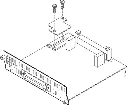
DSP expansion modules can be used if more than eight ports using high-complexity codecs are needed on the high-density analog telephony network module.
To install DSP expansion modules, follow these steps:
Step 1
Insert the connector on the DSP expansion module into the module connector on the network module. (See Figure 3.)

Note
Be sure to press firmly on the DSP expansion module until the board seats onto the connector.
Step 2
Insert the screws from the hardware kit through the DSP expansion module into the brackets on the network module.
Step 3
Install the network module into the router, as described in the "Installing Cisco Network Modules in Cisco Access Routers" section on page 5.
Figure 3 Installing a DSP Expansion Module
Adding Port Expansion Modules
Port expansion modules can be used to increase the number of ports supported on the high-density analog telephony network module.
To install port expansion modules, follow these steps:
Step 1
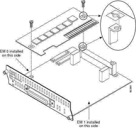
Decide if the expansion board is going in the EM0 slot or EM1 slot, as shown in Figure 4.
Step 2
Insert the connector on the port expansion module into the module connector on the network module, as shown in Figure 4. Use the alignment pins on the bracket to correctly align the expansion module. If the pin does not properly align with the expansion module, the rear bracket can be adjusted by loosening the screw underneath the bracket and tightening it when the module is correctly in place.

Note
Be sure to press firmly on the port expansion module until the board seats securely on the connector.

CautionFor each expansion module, two mounting screws must be installed with 6-8 lbs-in (67.8 N-cm) of torque. Failure to properly secure the expansion module to the base module with two screws compromises product reliability. In the case of FXO ports, failure to properly tighten both mounting screws causes FXO ground-start outgoing call operation to fail.
Step 3
Insert the screws from the hardware kit through the port expansion module into the brackets on the network module.

Warning
Failure to secure the expansion module to the base module with two screws defeats the earth ground, causing a potential safety hazard. Statement 347
Figure 4 Installing a Port Expansion Module
Step 4
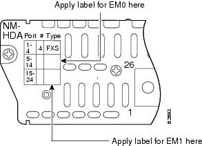
Apply the appropriate label on the front of the card, as shown in Figure 5.
Step 5
Install the network module into the router, as described in the "Installing Cisco Network Modules in Cisco Access Routers" section on page 5.
Figure 5 Label Locations for Expansion Ports
High-Density Analog Telephony Network Module LEDs
Figure 6 shows high-density analog telephony network module LEDs. Table 3 describes their meaning.
Figure 6 High-Density Analog Telephony Network Module LEDs

High-Density Analog Voice Card Pinouts
Figure 7 shows the RJ-21 connector wiring for the cable used for the high-density analog voice card; Table 4 lists the pinouts. The port usage depends on the type of expansion cards installed.
Figure 7 RJ-21 Connector Wiring
Related Documents
For additional information, see the following documents and resources.
Regulatory compliance and safety information
Cisco Network Modules and Interface Cards Regulatory Compliance and Safety Information
http://www.cisco.com/en/US/docs/routers/access/interfaces/rcsi/IOHrcsi.htmlCisco IOS software website and reference documentation
Cisco IOS Software http://www.cisco.com/web/psa/products/index.html?c=268438303
Obtaining Documentation, Obtaining Support, and Security Guidelines
For information on obtaining documentation, obtaining support, providing documentation feedback, security guidelines, and also recommended aliases and general Cisco documents, see the monthly What's New in Cisco Product Documentation, which also lists all new and revised Cisco technical documentation, at:
http://www.cisco.com/en/US/docs/general/whatsnew/whatsnew.html
CCDE, CCENT, CCSI, Cisco Eos, Cisco HealthPresence, Cisco IronPort, the Cisco logo, Cisco Lumin, Cisco Nexus, Cisco Nurse Connect, Cisco Pulse, Cisco StackPower, Cisco StadiumVision, Cisco TelePresence, Cisco Unified Computing System, Cisco WebEx, DCE, Flip Channels, Flip for Good, Flip Mino, Flipshare (Design), Flip Ultra, Flip Video, Flip Video (Design), Instant Broadband, and Welcome to the Human Network are trademarks; Changing the Way We Work, Live, Play, and Learn, Cisco Capital, Cisco Capital (Design), Cisco:Financed (Stylized), Cisco Store, and Flip Gift Card are service marks; and Access Registrar, Aironet, AllTouch, AsyncOS, Bringing the Meeting To You, Catalyst, CCDA, CCDP, CCIE, CCIP, CCNA, CCNP, CCSP, CCVP, Cisco, the Cisco Certified Internetwork Expert logo, Cisco IOS, Cisco Press, Cisco Systems, Cisco Systems Capital, the Cisco Systems logo, Cisco Unity, Collaboration Without Limitation, Continuum, EtherFast, EtherSwitch, Event Center, Explorer, Fast Step, Follow Me Browsing, FormShare, GainMaker, GigaDrive, HomeLink, iLYNX, Internet Quotient, IOS, iPhone, iQuick Study, IronPort, the IronPort logo, Laser Link, LightStream, Linksys, MediaTone, MeetingPlace, MeetingPlace Chime Sound, MGX, Networkers, Networking Academy, Network Registrar, PCNow, PIX, PowerKEY, PowerPanels, PowerTV, PowerTV (Design), PowerVu, Prisma, ProConnect, ROSA, ScriptShare, SenderBase, SMARTnet, Spectrum Expert, StackWise, The Fastest Way to Increase Your Internet Quotient, TransPath, WebEx, and the WebEx logo are registered trademarks of Cisco Systems, Inc. and/or its affiliates in the United States and certain other countries.
All other trademarks mentioned in this document or website are the property of their respective owners. The use of the word partner does not imply a partnership relationship between Cisco and any other company. (0908R)
Any Internet Protocol (IP) addresses used in this document are not intended to be actual addresses. Any examples, command display output, and figures included in the document are shown for illustrative purposes only. Any use of actual IP addresses in illustrative content is unintentional and coincidental.
© 2008 Cisco Systems, Inc. All rights reserved.
Contact Cisco
- Open a Support Case

- (Requires a Cisco Service Contract)
 Feedback