Alarm Interface Card Network Modules
Available Languages
Table Of Contents
Connecting Cisco Alarm Interface Controller Network Modules to the Network
Alarm Interface Controller Network Module
Connecting the AIC Network Module to the Network
Obtaining Documentation, Obtaining Support, and Security Guidelines
Connecting Cisco Alarm Interface Controller Network Modules to the Network
Revised: May 1, 2008, OL-12831-01
This guide describes how to connect Cisco Alarm Interface Controller (AIC) network modules to your network. It contains the following sections:
•
Alarm Interface Controller Network Module
•
Connecting the AIC Network Module to the Network
•
Obtaining Documentation, Obtaining Support, and Security Guidelines
Alarm Interface Controller Network Module
The AIC network module, shown in Figure 1, supports 64 alarm inputs. Fifty-six alarm inputs are discrete and can operate on dry contact closure when a patch panel is used. The last eight alarm inputs can be provisioned to accept analog inputs. The AIC network module has 16 control relay outputs.
The AIC network module can be connected to a patch panel. The patch panel provides the bias to the circuit.
The analog alarm inputs can be configured to monitor either DC voltage or current. The AIC can measure voltage from -60 to 60 V or current from 0 to 20 mA. The control relay can be operated to turn an external device on or off. When an event is detected, notification messages are sent to the Operations Support System (OSS) in the network operation center (NOC). These alarm inputs are configured in Cisco IOS software. Some reportable events include:
•
Equipment alarm
•
Building intrusion (door/window)
•
Temperature threshold violation
•
Voltage fluctuation
The AIC network module converts relay contact alarm signals to TL1 and SNMP message formats, providing TL1 over TCP/IP and SNMP protocols. All the contact closure-related alarms are routed and reported through the existing OSS and the associated OSS networks. With this network module, the Cisco router sends the TL1 or SNMP messages to the OSS autonomously or in response to TL1 or SNMP commands from the OSS.
The AIC network module is connected to the network using four high-density SCSI-type connectors on the front panel.
Figure 1 Alarm Interface Controller Network Module

Connecting the AIC Network Module to the Network
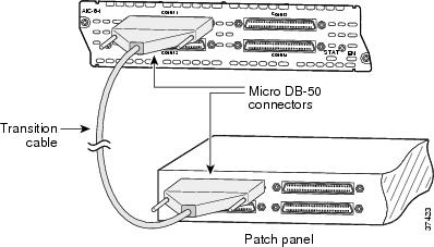
An AIC network module provides four 50-pin receptacles. Use cables that have male Micro DB-50 connectors at both ends with all conductors straight-wired. Central office equipment is cabled to the patch panel, and then cross-connected to the AIC cable.
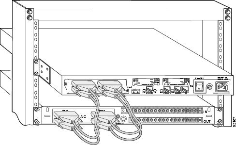
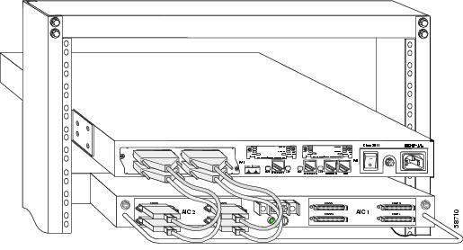
Two different patch panels can be used. The AIC-1 patch panel terminates one AIC and has voltage terminations with lugs and fuses for voltage monitoring. The AIC-2 patch panel terminates up to two AICs or 128 contact closure points
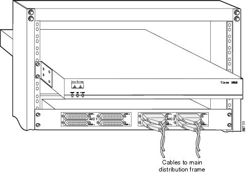
See Figure 2 through Figure 6 for examples of the AIC connections to the patch panels.
See the AIC data sheet for recommended patch panel and cable vendors.

CautionDamage to the AIC network module can occur if an alarm set for monitoring current is connected to a sensor for monitoring voltage. Make sure that your alarms are connected to the proper sensors.

CautionConnect the cable to the AIC before connecting it to the patch panel or other connection. Otherwise, voltage could be present on the male pins that connect to the AIC.

CautionThe signal I/O connections on this unit are intended only for connection to NEC/CEC Class 2 or equivalent circuit. This means that the voltages applied to I/O connections should not exceed 42.4 Vpk or 60 Vdc and it should be a limited/fused power source. For more details on Class 2 circuits, refer to the National Electrical Code/Canadian Electrical Code. This does not apply to the analog input/output terminal strip numbers 1-8 on the AIC-1 patch panel.

CautionThis unit is not intended for connection to exposed plant leads. Therefore, it should not be connected to circuit conductors that extend beyond one building and are run so as to be subject to accidental contact with AC main conductors, or are exposed to lightning on interbuilding circuits on the same premises.
Ports are numbered from right to left and from bottom to top, as labeled on the module rear panel. Pinouts for the AIC-1 patch panel are shown in Table 1. The connector 3 voltage monitor pinouts for AIC-1 are shown in Table 2. Pinouts for the AIC-2 patch panel are shown in Table 3.
Cables are not provided with the network module.
Figure 2 AIC Network Module Connection Diagram

Figure 3 AIC Network Module Faceplate Connections

Figure 4 AIC Network Module Connected to AIC-1 Patch Panel

Figure 5 AIC Network Module Connected to AIC-2 Patch Panel

Figure 6 AIC-2 Patch Panel Connected to MDF

Table 1 AIC-1 Connector Pinouts
1
Alarm Neg1
Alarm Neg 26
Alarm Neg 51
Control Common 1
26
Alarm Pos 1
Alarm Pos 26
Alarm Pos 51
Control N.O. 1
2
Alarm Neg 2
Alarm Neg 27
Alarm Neg 52
Control Common 2
27
Alarm Pos 2
Alarm Pos 27
Alarm Pos 52
Control N.O. 2
3
Alarm Neg 3
Alarm Neg 28
Alarm Neg 53
Control Common 3
28
Alarm Pos 3
Alarm Pos 28
Alarm Pos 53
Control N.O. 3
4
Alarm Neg 4
Alarm Neg 29
Alarm Neg 54
Control Common 4
29
Alarm Pos 4
Alarm Pos 29
Alarm Pos 54
Control N.O. 4
5
Alarm Neg 5
Alarm Neg 30
Alarm Neg 55
Control Common 5
30
Alarm Pos 5
Alarm Pos 30
Alarm Pos 55
Control N.O. 5
6
Alarm Neg 6
Alarm Neg 31
Alarm Neg 56
Control Common 6
31
Alarm Pos 6
Alarm Pos 31
Alarm Pos 56
Control N.O. 6
7
Alarm Neg 7
Alarm Neg 32
See Table 2
Control Common 7
32
Alarm Pos 7
Alarm Pos 32
See Table 2
Control N.O. 7
8
Alarm Neg 8
Alarm Neg 33
See Table 2
Control Common 8
33
Alarm Pos 8
Alarm Pos 33
See Table 2
Control N.O. 8
9
Alarm Neg 9
Alarm Neg 34
See Table 2
Control Common 9
34
Alarm Pos 9
Alarm Pos 34
See Table 2
Control N.O. 9
10
Alarm Neg 10
Alarm Neg 35
See Table 2
Control Common 10
35
Alarm Pos 10
Alarm Pos 35
See Table 2
Control N.O. 10
11
Alarm Neg 11
Alarm Neg 36
See Table 2
Control Common 11
36
Alarm Pos 11
Alarm Pos 36
See Table 2
Control N.O. 11
12
Alarm Neg 12
Alarm Neg 37
See Table 2
Control Common 12
37
Alarm Pos 12
Alarm Pos 37
See Table 2
Control N.O. 12
13
Alarm Neg 13
Alarm Neg 38
See Table 2
Control Common 13
38
Alarm Pos 13
Alarm Pos 38
See Table 2
Control N.O. 13
14
Alarm Neg 14
Alarm Neg 39
See Table 2
Control Common 14
39
Alarm Pos 14
Alarm Pos 39
See Table 2
Control N.O. 14
15
Alarm Neg 15
Alarm Neg 40
Not used
Control Common 15
40
Alarm Pos 15
Alarm Pos 40
Not used
Control N.O. 15
16
Alarm Neg 16
Alarm Neg 41
Not used
Control Common 16
41
Alarm Pos 16
Alarm Pos 41
Not used
Control N.O. 16
17
Alarm Neg 17
Alarm Neg 42
Not used
Not used
42
Alarm Pos 17
Alarm Pos 42
Not used
Not used
18
Alarm Neg 18
Alarm Neg 43
Not used
Not used
43
Alarm Pos 18
Alarm Pos 43
Not used
Not used
19
Alarm Neg 19
Alarm Neg 44
Not used
Not used
44
Alarm Pos 19
Alarm Pos 44
Not used
Not used
20
Alarm Neg 20
Alarm Neg 45
Not used
Not used
45
Alarm Pos 20
Alarm Pos 45
Not used
Not used
21
Alarm Neg 21
Alarm Neg 46
Not used
Not used
46
Alarm Pos 21
Alarm Pos 46
Not used
Not used
22
Alarm Neg 22
Alarm Neg 47
Not used
Not used
47
Alarm Pos 22
Alarm Pos 47
Not used
Not used
23
Alarm Neg 23
Alarm Neg 48
Not used
Not used
48
Alarm Pos 23
Alarm Pos 48
Not used
Not used
24
Alarm Neg 24
Alarm Neg 49
Not used
Not used
49
Alarm Pos 24
Alarm Pos 49
Not used
Not used
25
Alarm Neg 25
Alarm Neg 50
Not used
Not used
50
Alarm Pos 25
Alarm Pos 50
Not used
Not used
AIC Network Module LEDs
This section describes AIC network module LEDs. (See Figure 7.)
All network modules have an enable (EN) LED. This LED indicates that the module is receiving power from the router chassis.
The AIC network module also has a status (STAT) LED, which is a software-controlled bicolor (green and orange) LED. Both the EN and STAT LEDs turn on when the router is powered up, recycled, or power-cycled, or the AIC is hot-swapped. When the AIC starts to boot up, the STAT LED is initially turned off. It turns green when the software has initialized, has passed POST, and has established communication with IOS.
The STAT LED turns from green to orange when POST has failed or when the software encounters any other fatal fault in its firmware during normal operation.
Figure 7 AIC Network Module LEDs

Off
Off
Off
No power to the AIC
On
Off
Off
Software initializing
On
On
Off
Normal operation
On
Off
On
Fault encountered
Related Documents
For additional information, see the following documents and resources.
Regulatory compliance and safety information
Cisco Network Modules and Interface Cards Regulatory Compliance and Safety Information
http://www.cisco.com/en/US/docs/routers/access/interfaces/rcsi/IOHrcsi.htmlCisco IOS software website and reference documentation
Cisco IOS Software http://www.cisco.com/web/psa/products/index.html?c=268438303
Obtaining Documentation, Obtaining Support, and Security Guidelines
For information on obtaining documentation, obtaining support, providing documentation feedback, security guidelines, and also recommended aliases and general Cisco documents, see the monthly What's New in Cisco Product Documentation, which also lists all new and revised Cisco technical documentation, at:
http://www.cisco.com/en/US/docs/general/whatsnew/whatsnew.html
CCDE, CCENT, Cisco Eos, Cisco Lumin, Cisco StadiumVision, the Cisco logo, DCE, and Welcome to the Human Network are trademarks; Changing the Way We Work, Live, Play, and Learn is a service mark; and Access Registrar, Aironet, AsyncOS, Bringing the Meeting To You, Catalyst, CCDA, CCDP, CCIE, CCIP, CCNA, CCNP, CCSP, CCVP, Cisco, the Cisco Certified Internetwork Expert logo, Cisco IOS, Cisco Press, Cisco Systems, Cisco Systems Capital, the Cisco Systems logo, Cisco Unity, Collaboration Without Limitation, EtherFast, EtherSwitch, Event Center, Fast Step, Follow Me Browsing, FormShare, GigaDrive, HomeLink, Internet Quotient, IOS, iPhone, iQ Expertise, the iQ logo, iQ Net Readiness Scorecard, iQuick Study, IronPort, the IronPort logo, LightStream, Linksys, MediaTone, MeetingPlace, MGX, Networkers, Networking Academy, Network Registrar, PCNow, PIX, PowerPanels, ProConnect, ScriptShare, SenderBase, SMARTnet, Spectrum Expert, StackWise, The Fastest Way to Increase Your Internet Quotient, TransPath, WebEx, and the WebEx logo are registered trademarks of Cisco Systems, Inc. and/or its affiliates in the United States and certain other countries.
All other trademarks mentioned in this document or Website are the property of their respective owners. The use of the word partner does not imply a partnership relationship between Cisco and any other company. (0804R)
Any Internet Protocol (IP) addresses used in this document are not intended to be actual addresses. Any examples, command display output, and figures included in the document are shown for illustrative purposes only. Any use of actual IP addresses in illustrative content is unintentional and coincidental.
© 2008 Cisco Systems, Inc. All rights reserved.
Contact Cisco
- Open a Support Case

- (Requires a Cisco Service Contract)
 Feedback