IP VSAT Satellite WAN Network Modules
Available Languages
Table Of Contents
Connecting Cisco IP VSAT Satellite WAN Network Modules to the Network
Prerequisites for the NM-1VSAT-GILAT Network Module
Restrictions for the NM-1VSAT-GILAT Network Module
Information About the NM-1VSAT-GILAT Network Module
General Satellite Network Components
NM-1VSAT-GILAT Network Module Connectors
Outbound and Inbound Directions in a Satellite Communications Network
NM-1VSAT-GILAT Network Module LEDs
How to Install, Connect, or Replace the NM-1VSAT-GILAT Network Module
Installing the NM-1VSAT-GILAT Network Module in the Router Chassis
Connecting the NM-1VSAT-GILAT Network Module to the ODU
Connecting the NM-1VSAT-GILAT Network Module to the External Power Supply
Replacing the NM-1VSAT-GILAT Network Module in the Router Chassis
Performing Online Insertion and Removal of the NM-1VSAT-GILAT Network Module
Replacing the NM-1VSAT-GILAT Network Module in a Router
Obtaining Documentation, Obtaining Support, and Security Guidelines
Connecting Cisco IP VSAT Satellite WAN Network Modules to the Network
Revised: May 1, 2008, OL-12834-01
This guide describes how to connect Cisco IP VSAT satellite WAN network modules to your network. It contains the following sections:
•
NM-1VSAT-GILAT Network Module
•
Prerequisites for the NM-1VSAT-GILAT Network Module
•
Restrictions for the NM-1VSAT-GILAT Network Module
•
Information About the NM-1VSAT-GILAT Network Module
•
How to Install, Connect, or Replace the NM-1VSAT-GILAT Network Module
•
Obtaining Documentation, Obtaining Support, and Security Guidelines
NM-1VSAT-GILAT Network Module
The NM-1VSAT-GILAT network module provides Cisco modular access routers with two-way satellite WAN connectivity in Gilat SkyEdge-compatible satellite communications networks. The NM-1VSAT-GILAT network module functions as the indoor unit (IDU) of a very small aperture terminal (VSAT), or earthbound station of a satellite communications network. A "very small" dish antenna is called the outdoor unit (ODU) of a VSAT. As the IDU, the NM-1VSAT-GILAT network module serves as the interface between the ODU and the VSAT LAN. The ODU receives and sends signals to a satellite, and the satellite sends and receives signals from an earthbound central hub, which controls the entire operation of the satellite network. Figure 1 shows the NM-1VSAT-GILAT network module faceplate.
Figure 1 Cisco IP VSAT Satellite WAN Network Module (NM-1VSAT-GILAT) Faceplate

Prerequisites for the NM-1VSAT-GILAT Network Module
•
You need a router that supports the NM-1VSAT-GILAT network module. For a list of supported platforms, see the Cisco IP VSAT Satellite WAN Network Module (NM-1VSAT-GILAT) Data Sheet.
•
The NM-1VSAT-GILAT network module requires an associated central hub, which monitors and controls the satellite network. Therefore, you must take one of the following actions:
–
Subscribe to service from a Gilat SkyEdge satellite service provider.
–
Purchase your own Gilat SkyEdge hub equipment.
•
The NM-1VSAT-GILAT network module requires a "Sat Kit" provided by a Gilat SkyEdge satellite service provider. The Sat Kit includes the dish antenna equipment and an external power supply.

Warning
Only trained and qualified personnel should be allowed to install, replace, or service this equipment. Statement 1030

Note
For software-related prerequisites, see the Cisco IP VSAT Satellite WAN Network Module (NM-1VSAT-GILAT) Cisco IOS feature module.
Restrictions for the NM-1VSAT-GILAT Network Module
•
The NM-1VSAT-GILAT network module is supported only in Gilat SkyEdge-compatible satellite communications networks. For more information, go to http://www.gilat.com/.
•
One-way satellite connectivity is currently not supported.
•
The NM-1VSAT-GILAT network module is designed for Ku-band and C-band satellite networks using the Gilat SkyEdge Frequency and Time Division Multiple Access (FTDMA) technology. The NM-1VSAT-GILAT network module is not compatible with these items:
–
Other frequency bands, such as Ka-band
–
Other satellite TDMA systems, including Digital Video Broadcasting-Return Channel by Satellite (DVB-RCS), and Data Over Cable Service Interface Specification (DOCSIS)
–
Other media access methods, such as Single Channel Per Carrier (SCPC)
•
The following hardware tasks are not described in this document and must be performed by a Gilat SkyEdge-certified installer:
–
Installing and aligning the dish antenna
–
Running cables from the ODU to the IDU area
–
Connecting two NM-1VSAT-GILAT network modules to one ODU for Hot Standby Router Protocol (HSRP) redundancy
•
To avoid damaging the NM-1VSAT-GILAT network module, disconnect the power supply from the ODU PWR connector on the NM-1VSAT-GILAT network module before you attempt any of the following actions:
–
Connecting a cable to the RF-IN or RF-OUT connector
–
Disconnecting a cable from the RF-IN or RF-OUT connector
–
Inserting the NM-1VSAT-GILAT network module into the router chassis
–
Removing the NM-1VSAT-GILAT network module from the router chassis
•
After completing the hardware installation, moving the router with the installed NM-1VSAT-GILAT network module may require longer radio frequency (RF) cables. Depending on the ODU type and the additional length required for the cables, you may need a technician to install line amplifiers. Contact your satellite service provider if you plan to extend your cables by more than 35 feet (11 m).

Note
For software-related restrictions, see the Cisco IP VSAT Satellite WAN Network Module (NM-1VSAT-GILAT) Cisco IOS feature module.
Information About the NM-1VSAT-GILAT Network Module
Before performing the tasks in this document, you should understand the following concepts:
•
General Satellite Network Components
•
NM-1VSAT-GILAT Network Module Connectors
•
Outbound and Inbound Directions in a Satellite Communications Network
•
NM-1VSAT-GILAT Network Module LEDs

Note
For NM-1VSAT-GILAT network module features and benefits, supported hardware and software, and other product information, see the Cisco IP VSAT Satellite WAN Network Module (NM-1VSAT-GILAT) Data Sheet.
General Satellite Network Components
Figure 2 shows a satellite communications network that includes NM-1VSAT-GILAT network modules.

Note
Not shown in Figure 2 are the terrestrial WAN connections that are also commonly used to connect VSAT routers to the Internet or an intranet. A terrestrial WAN connection can be used to back up a satellite link or can serve as a primary link that is backed up by a satellite link.
Figure 2 Satellite Communications Network Using the NM-1VSAT-GILAT Network Module
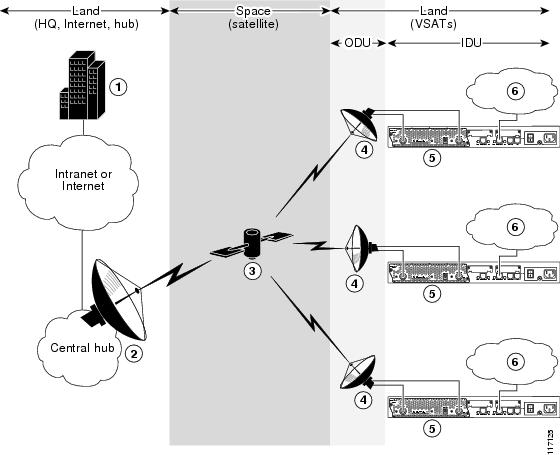
1 ODU = outdoor unit
2 VSAT = very small aperture terminal
At a high level, the many components of an enterprise satellite communications network can be divided into three categories:
•
Hub
Satellite
Placed in orbit around the earth, a satellite is a specialized repeater that receives radio-frequency signals from earth stations and retransmits them to other earth stations. The satellite also amplifies the signals and switches the frequencies between the uplink and the downlink carriers. Gilat SkyEdge systems use geostationary satellites with a fixed satellite-to-earth delay of about 250 ms.
Hub
The central hub—sometimes referred to as the "master earth station" but most often simply called the "hub"—contains many components, including:
•
Large dish antenna (15 to 36 feet [4.5 to 11 m] in diameter)
•
Satellite network management system (NMS) and provisioning stations, from which a network operator can monitor and control all components of the enterprise satellite communications network.
•
Baseband equipment that handles satellite access, routing between the hub and remote earth stations, dial backup, quality of service (QoS), TCP acceleration, and HTTP acceleration.
•
Optional components: web caches, MPEG transport coder/decoder, application server farms, and audio/video broadcast programming devices.

Note
Throughout this document, the "hub" refers specifically to a Gilat SkyEdge hub.
VSATs
A very small aperture terminal (VSAT) is an earth station that can be divided into two areas:
•
Indoor unit (IDU), which generally serves to connect the local network to the hub through the satellite link. The IDU components vary, depending on the functions required, but the components typically include these items:
–
Integrated receiver decoder (IRD) for the tuning
–
Demodulation and decoding of L-band or other type of intermediate frequency (IF) passed from the dish
–
End-user input/output
•
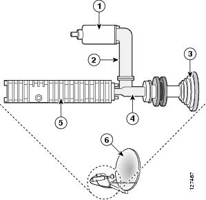
Outdoor unit (ODU), which includes a "very small" dish antenna (2 to 6 feet [0.5 to 2 m] in diameter) and its components, shown in Figure 3. The ODU is typically mounted on a building roof or outer wall, or placed on the ground.
The NM-1VSAT-GILAT network module functions as the IDU of a VSAT and is connected to the ODU through coaxial cables. A power supply is connected to the NM-1VSAT-GILAT network module to provide power over the coaxial cables to the ODU.

Note
The NM-1VSAT-GILAT network module supports only the ODU equipment and power supply that comes in the "Sat Kit" provided by a Gilat SkyEdge satellite service provider.
Figure 3 ODU Components
NM-1VSAT-GILAT Network Module Connectors
Table 1 lists the physical connectors that appear on the NM-1VSAT-GILAT network module faceplate.
Outbound and Inbound Directions in a Satellite Communications Network
The outbound direction applies to signals transmitted from the hub to the VSAT. Within a VSAT network, the outbound direction applies to RF communication from the dish antenna (ODU) to the NM-1VSAT-GILAT network module (IDU). From the VSAT perspective, the outbound direction is the receive path. Gilat SkyEdge outbound signals include user data and timing data that are compatible with the Digital Video Broadcasting-Satellite (DVB-S) standard.
The inbound direction applies to signals transmitted from the VSAT to the hub. Within a VSAT network, the inbound direction applies to RF communication from the NM-1VSAT-GILAT network module (IDU) to the dish antenna (ODU). From the VSAT perspective, the inbound direction is the transmit path. Inbound signals include user data and retransmission requests.
NM-1VSAT-GILAT Network Module LEDs
The Cisco IP VSAT satellite WAN network module (NM-1VSAT-GILAT) has six LEDs, shown in Figure 4 and described in Table 2.
Figure 4 NM-1VSAT-GILAT Network Module LEDs

Table 2 NM-1VSAT-GILAT Network Module LED Descriptions
Ref.1
EXT DC
Blinking
ODU1 power DC level is correct, and the network module VSAT2 software is running.
Normal indication. No action required.
Steady on
ODU power supply is connected properly, but the network module VSAT software is not running.
Wait until the VSAT software completes the boot process.
Off
ODU power supply is not connected or is outside the specified DC range.
Check ODU power supply connections. See the "Connecting the NM-1VSAT-GILAT Network Module to the External Power Supply" section.
2
RX LOCK
On
Normal indication. No action required.
Off
NM-1VSAT-GILAT network module does not see or recognize the DVB carrier signal from the hub.
The VSAT parameters are configured incorrectly. See the Cisco IP VSAT Satellite WAN Network Module (NM-1VSAT-GILAT) Cisco IOS feature module.
The network module is not properly connected to the LNB.5 Check the RF6 cables or contact your satellite service provider.
The dish antenna is misaligned. Contact your satellite service provider.
There is a hub failure, or the hub is configured incorrectly. Contact your satellite service provider.
3
SYNC
On
NM-1VSAT-GILAT network module is synchronized with the hub timing.
Normal indication. No action required.
Off
NM-1VSAT-GILAT network module is not synchronized with the hub timing.
If the RX LOCK LED is also off, then see the corrective actions for RX LOCK.
If the RX LOCK LED is on while the SYNC LED is off, then the following apply:
•
The VSAT parameters are configured incorrectly. See the Cisco IP VSAT Satellite WAN Network Module (NM-1VSAT-GILAT) Cisco IOS feature module.
•
There is a hub failure, or the hub is configured incorrectly. Contact your satellite service provider.
4
ON LINE
On
IP connectivity to the hub is fully established.
Normal indication. No action required.
Off
IP connectivity to the hub was unsuccessful.
If the SYNC LED is also off, then see the corrective actions for SYNC.
If the SYNC LED is on while the ON LINE LED is off, then the following apply:
•
There is a problem somewhere in the return path from the network module to the hub. Check the cabling between the RF-OUT connector and the SSPA.7
•
The SSPA may not be working. Contact your satellite service provider.
•
The dish antenna is misaligned. Contact your satellite service provider.
•
There is a hub failure, or the hub is configured incorrectly. Contact your satellite service provider.
5
TX
Flickering
Inbound8 transmission is in progress.
Normal indication. No action required.
Off
No inbound transmission is in progress.
If you are concerned about the TX LED being off, then try to ping the hub or another destination on the other side of the satellite link. If the TX LED does not flicker during the ping, then the network module is not attempting to send data to the hub.
•
Wait until the VSAT software completes the boot process.
•
Verify that your Cisco IOS software configuration is correct. See the Cisco IP VSAT Satellite WAN Network Module (NM-1VSAT-GILAT) Cisco IOS feature module.
•
The VSAT software has failed. Contact your satellite service provider.
6
EN
On
The router's Cisco IOS software recognizes the network module.
Normal indication. No action required.
Off
The router's Cisco IOS software does not recognize the network module.
Verify that the network module is properly installed in the router chassis. See the "Installing Cisco Network Modules in Cisco Access Routers" guide.
1 ODU = outdoor unit.
2 VSAT = very small aperture terminal.
3 DVB = Digital Video Broadcasting.
4 The receive direction at the remote VSAT is called the outbound direction from the hub. See the "Outbound and Inbound Directions in a Satellite Communications Network" section.
5 LNB = low noise block converter.
6 RF = radio frequency.
7 SSPA = solid state block converter and power amplifier.
8 The transmit direction at the remote VSAT is called the inbound direction to the hub. See the "Outbound and Inbound Directions in a Satellite Communications Network" section.
How to Install, Connect, or Replace the NM-1VSAT-GILAT Network Module
This section contains the following procedures, each of which may or may not be required, depending on which tasks your satellite service provider performs for you:
•
Installing the NM-1VSAT-GILAT Network Module in the Router Chassis
•
Connecting the NM-1VSAT-GILAT Network Module to the ODU
•
Connecting the NM-1VSAT-GILAT Network Module to the External Power Supply
•
Replacing the NM-1VSAT-GILAT Network Module in the Router Chassis
Installing the NM-1VSAT-GILAT Network Module in the Router Chassis
To install the NM-1VSAT-GILAT network module in the router chassis, see the "Installing Cisco Network Modules in Cisco Access Routers" guide.
Connecting the NM-1VSAT-GILAT Network Module to the ODU
This section describes how to connect the NM-1VSAT-GILAT network module to the ODU.
Shielded RG-6, RG-11, or both types of RF cables are used to connect the NM-1VSAT-GILAT network module to the ODU. Typically, a satellite service provider installation technician installs the ODU, connects RG-11 cables to the dish antenna, and runs the RG-11 cables to the area near the router. The technician also typically terminates the RG-11 cables and adds short RG-6 cables, which are then connected to the NM-1VSAT-GILAT network module in the router.

Note
If an installation technician has already connected the NM-1VSAT-GILAT to the ODU, then do not perform this task. Instead, proceed directly to the "Connecting the NM-1VSAT-GILAT Network Module to the External Power Supply" section.
Prerequisites
•
Install the NM-1VSAT-GILAT network module in the router chassis.
•
Make sure that your ODU is installed and connected to RF cables that lead to the area near the NM-1VSAT-GILAT network module. Contact your satellite service provider for ODU and cable installation information.
Steps
To connect the NM-1VSAT-GILAT network module to the ODU, follow these steps:
Step 1
Disconnect the power supply from the ODU PWR connector on the NM-1VSAT-GILAT network module.

CautionMake sure that the external power supply is disconnected from the NM-1VSAT-GILAT network module before connecting cables to the RF-IN or RF-OUT connectors. If the external power supply is connected to the ODU PWR connector while you connect or disconnect cables to the RF-IN or RF-OUT connectors, you might short-circuit the NM-1VSAT-GILAT network module F connectors. This may cause the network module to reset itself or lose data.
Step 2
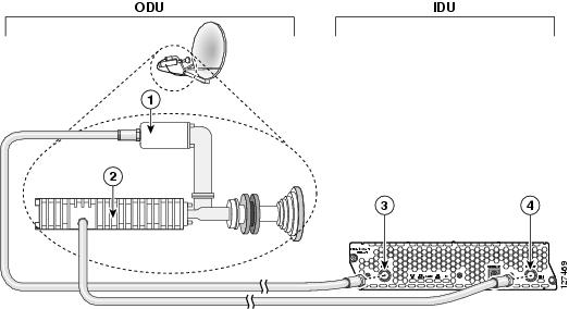
Take the indoor end of the cable that leads to the LNB, and connect it to the RF-IN connector on the NM-1VSAT-GILAT network module. (See Figure 5.)
Step 3
Take the indoor end of the cable that leads to the SSPA, and connect it to the RF-OUT connector on the NM-1VSAT-GILAT network module. (See Figure 5.)
Figure 5 Connecting the NM-1VSAT-GILAT Network Module to the ODU
What to Do Next
Proceed to the "Connecting the NM-1VSAT-GILAT Network Module to the External Power Supply" section.
Connecting the NM-1VSAT-GILAT Network Module to the External Power Supply
This section describes how to connect the NM-1VSAT-GILAT network module to the external power supply that comes in the "Sat Kit" provided by a Gilat SkyEdge satellite service provider. The NM-1VSAT-GILAT network module requires additional power to operate the ODU, which includes the dish antenna and its parts, such as the LNB, SSPA, OMT, and feed horn.

Note
If an installation technician has already connected a power supply to the ODU, then do not perform this task. Instead, proceed directly to the software configuration tasks for your NM-1VSAT-GILAT network module. See the Cisco IP VSAT Satellite WAN Network Module (NM-1VSAT-GILAT) Cisco IOS feature module.
Prerequisites
•
Install the NM-1VSAT-GILAT network module in the router chassis.
•
Connect the NM-1VSAT-GILAT network module to the ODU. See the "Connecting the NM-1VSAT-GILAT Network Module to the ODU" section.
Restrictions
Only use the power supply provided in the Gilat ODU kit. Use of any other power supply will void the warranties for your NM-1VSAT-GILAT network module and outdoor equipment.
Steps
To connect the NM-1VSAT-GILAT network module to the external power supply, follow these steps:
Step 1
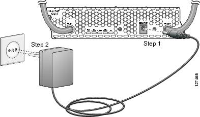
Connect the power supply cable to the ODU PWR connector on the NM-1VSAT-GILAT network module. (See Figure 6.)
Step 2
Connect the power supply to a general-purpose electrical outlet. (For the United States, see Figure 6. For Europe, see Figure 7.)
Figure 6 Connecting the NM-1VSAT-GILAT Network Module to the Power Supply (USA)
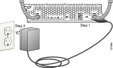
Figure 7 Connecting the NM-1VSAT-GILAT Network Module to the Power Supply (Europe)
What to Do Next
Proceed to the software configuration for your NM-1VSAT-GILAT network module. See the Cisco IP VSAT Satellite WAN Network Module (NM-1VSAT-GILAT) Cisco IOS feature module.
Replacing the NM-1VSAT-GILAT Network Module in the Router Chassis
This section describes how to replace the NM-1VSAT-GILAT network module in your router. Complete one of the following tasks, depending on whether or not your router supports online insertion and removal (OIR):
•
Performing Online Insertion and Removal of the NM-1VSAT-GILAT Network Module
•
Replacing the NM-1VSAT-GILAT Network Module in a Router
Performing Online Insertion and Removal of the NM-1VSAT-GILAT Network Module
The online insertion and removal (OIR) feature enables some Cisco modular access routers to support the replacement of network modules without switching off the router or affecting the operation of other interfaces. Also, routing information is maintained during OIR of network modules.
If your router does not support OIR, do not perform this task to replace your NM-1VSAT-GILAT network module. Instead, go to the "Replacing the NM-1VSAT-GILAT Network Module in a Router" section.
Restrictions
•
Only the Cisco 3745 and Cisco 3845 routers support OIR of the NM-1VSAT-GILAT network module.
•
All connections made through the NM-1VSAT-GILAT network module are reset during OIR.
•
You must perform OIR with similar modules. If you remove a network module, install another network module exactly like it in its place.
Steps
To perform OIR of the NM-1VSAT-GILAT network module in your router, follow these steps:
Step 1
Initiate a console session with your router.
Step 2
Enter satellite interface configuration mode and shut down the interface:
Router> enableRouter# configure terminalRouter(config)# interface satellite slot/0Router(config-if)# shutdownRouter(config-if)# endRouter#Step 3
Disconnect the power supply cable from the ODU PWR connector on the NM-1VSAT-GILAT network module.

CautionMake sure that the external power supply is disconnected from the NM-1VSAT-GILAT network module before connecting or disconnecting cables from the RF-IN or RF-OUT connectors. If the external power supply is connected to the ODU PWR connector while you connect or disconnect cables from the RF-IN or RF-OUT connectors, you might short-circuit the NM-1VSAT-GILAT network module F connectors. This may cause the network module to reset itself or lose data.
Step 4
(Optional but recommended) Label the RF cables "RF-IN" and "RF-OUT."
Step 5
Disconnect the cables from the RF-IN and RF-OUT connectors on the NM-1VSAT-GILAT network module.
Step 6
Using a number 1 Phillips or flat-blade screwdriver, loosen the captive mounting screws on the network module faceplate.

CautionTo avoid damaging the network module, always handle the network module by the handle or faceplate. Do not touch the circuit board.
Step 7
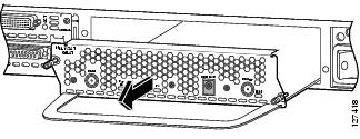
Using the module handle, pull the network module from the router slot. (See Figure 8.)
Figure 8 Removing a Single-Wide Network Module
Step 8
Align the replacement network module with the guides in the chassis walls or slot divider and slide it gently into the slot. (See Figure 9.)
Figure 9 Installing a Single-Wide Network Module

Step 9
Using the network module handle, push the NM-1VSAT-GILAT network module into place until you feel the edge connector seat securely into the connector on the router backplane. The network module faceplate should contact the chassis rear panel.
Step 10
Using a number 1 Phillips or flat-blade screwdriver, tighten the captive mounting screws on the network module faceplate.

CautionMake sure that the external power supply is disconnected from the NM-1VSAT-GILAT network module before connecting or disconnecting cables from the RF-IN or RF-OUT connectors. If the external power supply is connected to the ODU PWR connector while you connect or disconnect cables from the RF-IN or RF-OUT connectors, you might short-circuit the NM-1VSAT-GILAT network module F connectors. This may cause the network module to reset itself or lose data.
Step 11
Connect the RF cables to the RF-IN and RF-OUT connectors on the NM-1VSAT-GILAT network module.
Step 12
Connect the power supply cable to the ODU PWR connector on the NM-1VSAT-GILAT network module.
Step 13
Confirm that the network module LEDs come on. For more information about the LEDs, see the "NM-1VSAT-GILAT Network Module LEDs" section.
Step 14
Initiate a console session with your router.
Step 15
Enter satellite interface configuration mode, and enable the satellite interface:
Router> enableRouter# configure terminalRouter(config)# interface satellite slot/0Router(config-if)# no shutdownRouter(config-if)# endRouter#
What to Do Next
Configure the initial VSAT parameters for the new NM-1VSAT-GILAT network module. See the
Cisco IP VSAT Satellite WAN Network Module (NM-1VSAT-GILAT) Cisco IOS feature module.
Note
Satellite initial configuration mode can only be accessed by a password that is unique to each NM-1VSAT-GILAT network module. If an installation technician does not configure the initial VSAT parameters, then your satellite service provider will provide the password for your new NM-1VSAT-GILAT network module.
Replacing the NM-1VSAT-GILAT Network Module in a Router
This section describes how to replace the NM-1VSAT-GILAT network module when your router does not support online insertion and removal (OIR). If your router supports OIR, do not perform this task. Instead, go to the "Performing Online Insertion and Removal of the NM-1VSAT-GILAT Network Module" section.
To replace the NM-1VSAT-GILAT network module in your router, follow these steps:
Step 1
Disconnect the power supply cable from the ODU PWR connector on the NM-1VSAT-GILAT network module.

CautionMake sure that the external power supply is disconnected from the NM-1VSAT-GILAT network module before connecting or disconnecting cables from the RF-IN or RF-OUT connectors. If the external power supply is connected to the ODU PWR connector while you connect or disconnect cables from the RF-IN or RF-OUT connectors, you might short-circuit the NM-1VSAT-GILAT network module F connectors. This may cause the network module to reset itself or lose data.
Step 2
(Optional but recommended) Label the RF cables "RF-IN" and "RF-OUT."
Step 3
Disconnect the cables from the RF-IN and RF-OUT connectors on the NM-1VSAT-GILAT network module.
Step 4
Turn off electrical power to the router. Leave the power cable plugged in to channel ESD voltages to ground.
The following warning applies only to routers that use DC power.

Warning
Before performing any of the following procedures, ensure that power is removed from the DC circuit. To ensure that all power is OFF, locate the circuit breaker on the panel board that services the DC circuit, switch the circuit breaker to the OFF position, and tape the switch handle of the circuit breaker in the OFF position. Statement 7

Timesaver
Label the cables or prepare a network cabling diagram before removing cables.
Step 5
Remove all network cables, including telephone cables, from the rear panel of the router.
Step 6
Using a number 1 Phillips or flat-blade screwdriver, loosen the captive mounting screws on the NM-1VSAT-GILAT network module faceplate.

CautionTo avoid damaging the network module, always handle the network module by the handle or faceplate. Do not touch the circuit board.
Step 7
Using the module handle, pull the network module from the router slot. (See Figure 10.)
Figure 10 Removing a Single-Wide Network Module

Step 8
Align the replacement network module with the guides in the chassis walls or slot divider and slide it gently into the slot. (See Figure 11.)
Figure 11 Installing a Single-Wide Network Module

Step 9
Using the network module handle, push the module into place until you feel the edge connector seat securely into the connector on the router backplane. The network module faceplate should contact the chassis rear panel.
Step 10
Using a number 1 Phillips or flat-blade screwdriver, tighten the captive mounting screws on the network module faceplate.
Step 11
Turn on electrical power to the router.
The following warning applies only to routers that use DC power.

Warning
After wiring the DC power supply, remove the tape from the circuit breaker switch handle and reinstate power by moving the handle of the circuit breaker to the ON position. Statement 8

CautionMake sure that the external power supply is disconnected from the NM-1VSAT-GILAT network module before connecting or disconnecting cables from the RF-IN or RF-OUT connectors. If the external power supply is connected to the ODU PWR connector while you connect or disconnect cables from the RF-IN or RF-OUT connectors, you might short-circuit the NM-1VSAT-GILAT network module F connectors. This may cause the network module to reset itself or lose data.
Step 12
Connect the RF cables to the RF-IN and RF-OUT connectors on the NM-1VSAT-GILAT network module.
Step 13
Connect the power supply cable to the ODU PWR connector on the NM-1VSAT-GILAT network module.
Step 14
Reconnect all other network cables, including telephone cables, to the rear panel of the router.
Step 15
Confirm that the NM-1VSAT-GILAT network module LEDs come on. For more information about the LEDs, see the "NM-1VSAT-GILAT Network Module LEDs" section.
What to Do Next
Configure the initial VSAT parameters for the new NM-1VSAT-GILAT network module. See the
Cisco IP VSAT Satellite WAN Network Module (NM-1VSAT-GILAT) Cisco IOS feature module.
Note
Satellite initial configuration mode can only be accessed by a password that is unique to each NM-1VSAT-GILAT network module. If an installation technician does not configure the initial VSAT parameters, then your satellite service provider will provide the password for your new NM-1VSAT-GILAT network module.
Related Documents
For additional information, see the following documents and resources.
Cisco IOS software configuration for the NM-1VSAT-GILAT network module
Cisco IP VSAT Satellite WAN Network Module (NM-1VSAT-GILAT)
http://www.cisco.com/en/US/docs/ios/12_3t/12_3t14/feature/guide/gtstltnm.htmlRegulatory compliance and safety information
Cisco Network Modules and Interface Cards Regulatory Compliance and Safety Information
http://www.cisco.com/en/US/docs/routers/access/interfaces/rcsi/IOHrcsi.htmlCisco IOS software website and reference documentation
Cisco IOS Software http://www.cisco.com/web/psa/products/index.html?c=268438303
Obtaining Documentation, Obtaining Support, and Security Guidelines
For information on obtaining documentation, obtaining support, providing documentation feedback, security guidelines, and also recommended aliases and general Cisco documents, see the monthly What's New in Cisco Product Documentation, which also lists all new and revised Cisco technical documentation, at:
http://www.cisco.com/en/US/docs/general/whatsnew/whatsnew.html
CCDE, CCENT, Cisco Eos, Cisco Lumin, Cisco StadiumVision, the Cisco logo, DCE, and Welcome to the Human Network are trademarks; Changing the Way We Work, Live, Play, and Learn is a service mark; and Access Registrar, Aironet, AsyncOS, Bringing the Meeting To You, Catalyst, CCDA, CCDP, CCIE, CCIP, CCNA, CCNP, CCSP, CCVP, Cisco, the Cisco Certified Internetwork Expert logo, Cisco IOS, Cisco Press, Cisco Systems, Cisco Systems Capital, the Cisco Systems logo, Cisco Unity, Collaboration Without Limitation, EtherFast, EtherSwitch, Event Center, Fast Step, Follow Me Browsing, FormShare, GigaDrive, HomeLink, Internet Quotient, IOS, iPhone, iQ Expertise, the iQ logo, iQ Net Readiness Scorecard, iQuick Study, IronPort, the IronPort logo, LightStream, Linksys, MediaTone, MeetingPlace, MGX, Networkers, Networking Academy, Network Registrar, PCNow, PIX, PowerPanels, ProConnect, ScriptShare, SenderBase, SMARTnet, Spectrum Expert, StackWise, The Fastest Way to Increase Your Internet Quotient, TransPath, WebEx, and the WebEx logo are registered trademarks of Cisco Systems, Inc. and/or its affiliates in the United States and certain other countries.
All other trademarks mentioned in this document or Website are the property of their respective owners. The use of the word partner does not imply a partnership relationship between Cisco and any other company. (0804R)
Any Internet Protocol (IP) addresses used in this document are not intended to be actual addresses. Any examples, command display output, and figures included in the document are shown for illustrative purposes only. Any use of actual IP addresses in illustrative content is unintentional and coincidental.
© 2008 Cisco Systems, Inc. All rights reserved.
Contact Cisco
- Open a Support Case

- (Requires a Cisco Service Contract)
 Feedback