Table Of Contents
Medium Enterprise Design Profile (MEDP)—LAN Design
Medium Enterprise LAN Design Models
Remote Large Campus Site Design
Remote Medium Campus Site Design
Remote Small Campus Network Design
Multi-Tier LAN Design Models for Medium Enterprise
Campus Core Layer Network Design
Core Layer Design Option 1—Cisco Catalyst 6500-E-Based Core Network
Core Layer Design Option 2—Cisco Catalyst 4500-E-Based Campus Core Network
Core Layer Design Option 3—Cisco Catalyst 4500-E-Based Collapsed Core Campus Network
Campus Distribution Layer Network Design
Distribution Layer Design Option 1—Cisco Catalyst 6500-E Based Distribution Network
Distribution Layer Design Option 2—Cisco Catalyst 4500-E-Based Distribution Network
Distribution Layer Design Option 3—Cisco Catalyst 3750-X StackWise-Based Distribution Network
Campus Access Layer Network Design
Access Layer Design Option 1—Modular/StackWise Plus/FlexStack Access Layer Network
Access Layer Design Option 2—Fixed Configuration Access Layer Network
Deploying Medium Enterprise Network Foundation Services
Implementing LAN Network Infrastructure
Deploying Cisco Catalyst 6500-E in VSS Mode
Deploying Cisco Catalyst 4500-E
Deploying Cisco Catalyst 3750-X StackWise Plus
Deploying Cisco Catalyst 3560-X and 2960-S FlexStack
Designing EtherChannel Network
Network Foundational Technologies for LAN Design
Designing the Core Layer Network
Designing the Campus Distribution Layer Network
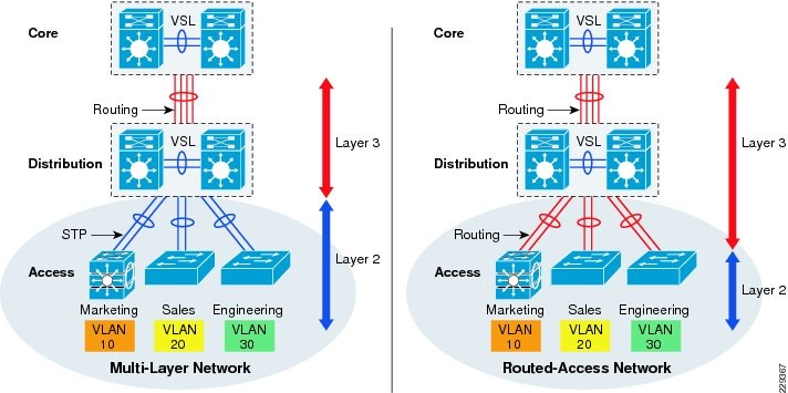
Designing the Multilayer Network
Spanning-Tree in Multilayer Network
Designing the Routed Access Network
Multicast for Application Delivery
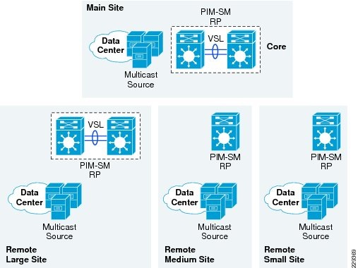
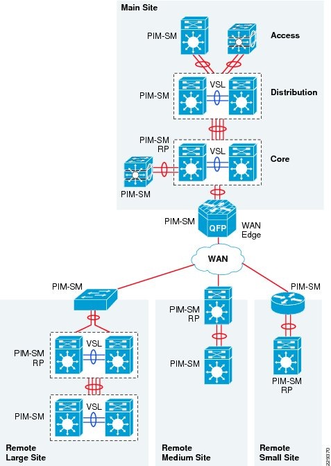
Designing PIM Rendezvous Point
QoS for Application Performance Optimization
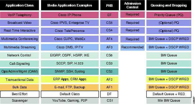
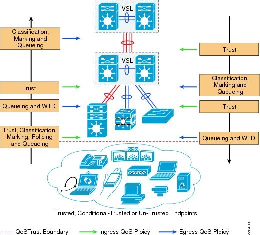
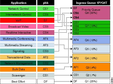
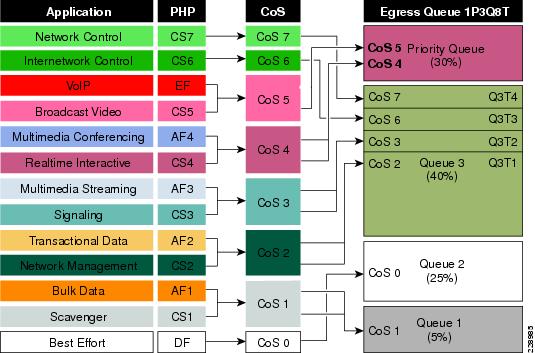
Medium Enterprise LAN QoS Framework
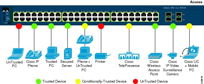
Designing Medium Enterprise LAN QoS Trust Boundary and Policies
Medium Enterprise LAN QoS Overview
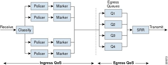
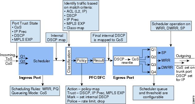
Deploying QoS in Campus LAN Network
QoS in Catalyst Fixed Configuration Switches
High-Availability in LAN Network Design
Medium Enterprise High-Availability Framework
Baselining Campus High Availability
Operational Resiliency Overview
Design Strategies for Network Survivability
Implementing Network Resiliency
Implementing Device Resiliency
Implementing Operational Resiliency
Medium Enterprise Design Profile (MEDP)—LAN Design
LAN Design
The Medium Enterprise LAN design is a multi-campus design, where a campus consists of multiple buildings and services at each location, as shown in Figure 2-1.
Figure 2-1 Medium Enterprise LAN Design
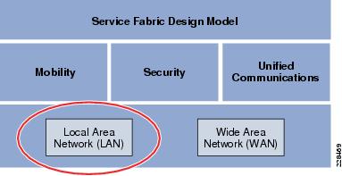
Figure 2-2 shows the service fabric design model used in the medium enterprise LAN design.
Figure 2-2 Medium Enterprise LAN Design
This chapter focuses on the LAN component of the overall design. The LAN component consists of the LAN framework and network foundation technologies that provide baseline routing and switching guidelines. The LAN design interconnects several other components, such as endpoints, data center, WAN, and so on, to provide a foundation on which mobility, security, and unified communications (UC) can be integrated into the overall design.
This LAN design provides guidance on building the next-generation medium enterprise network, which becomes a common framework along with critical network technologies to deliver the foundation for the service fabric design. This chapter is divided into following sections:
•
LAN design principles—Provides proven design choices to build various types of LANs.
•
•
•
LAN Design Principles
Any successful design or system is based on a foundation of solid design theory and principles. Designing the LAN component of the overall medium enterprise LAN service fabric design model is no different than designing any large networking system. The use of a guiding set of fundamental engineering design principles serves to ensure that the LAN design provides for the balance of availability, security, flexibility, and manageability required to meet current and future advanced and emerging technology needs. This chapter provides design guidelines that are built upon the following principles to allow a medium enterprise network architect to build enterprise campuses that are located in different geographical locations:
•
–
–
–
•
•
•
These are not independent principles. The successful design and implementation of a campus network requires an understanding of how each of these principles applies to the overall design. In addition, understanding how each principle fits in the context of the others is critical in delivering a hierarchical, modular, resilient, and flexible network required by medium enterprises today.
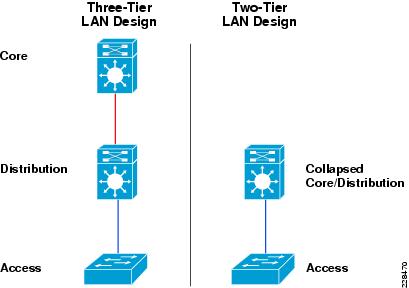
Designing the medium enterprise LAN building blocks in a hierarchical fashion creates a flexible and resilient network foundation that allows network architects to overlay the security, mobility, and UC features essential to the service fabric design model, as well as providing an interconnect point for the WAN aspect of the network. The two proven, time-tested hierarchical design frameworks for LAN networks are the three-tier layer and the two-tier layer models, as shown in Figure 2-3.
Figure 2-3 Three-Tier and Two-Tier LAN Design Models
The key layers are access, distribution and core. Each layer can be seen as a well-defined structured module with specific roles and functions in the LAN network. Introducing modularity in the LAN hierarchical design further ensures that the LAN network remains resilient and flexible to provide critical network services as well as to allow for growth and changes that may occur in a medium enterprise.
•
The access layer represents the network edge, where traffic enters or exits the campus network. Traditionally, the primary function of an access layer switch is to provide network access to the user. Access layer switches connect to the distribution layer switches to perform network foundation technologies such as routing, quality of service (QoS), and security.
To meet network application and end-user demands, the next-generation Cisco Catalyst switching platforms no longer simply switch packets, but now provide intelligent services to various types of endpoints at the network edge. Building intelligence into access layer switches allows them to operate more efficiently, optimally, and securely.
•
The distribution layer interfaces between the access layer and the core layer to provide many key functions, such as the following:
–
–
–
–
•
The core layer is the network backbone that connects all the layers of the LAN design, providing for connectivity between end devices, computing and data storage services located within the data center and other areas, and services within the network. The core layer serves as the aggregator for all the other campus blocks, and ties the campus together with the rest of the network.
Note
Figure 2-4 shows a sample three-tier LAN network design for medium enterprises where the access, distribution, and core are all separate layers. To build a simplified, cost-effective, and efficient physical cable layout design, Cisco recommends building an extended-star physical network topology from a centralized building location to all other buildings on the same campus.
Figure 2-4 Three-Tier LAN Network Design Example
The primary purpose of the core layer is to provide fault isolation and backbone connectivity. Isolating the distribution and core into separate layers creates a clean delineation for change control between activities affecting end stations (laptops, phones, and printers) and those that affect the data center, WAN, or other parts of the network. A core layer also provides for flexibility in adapting the campus design to meet physical cabling and geographical challenges. If necessary, a separate core layer can use a different transport technology, routing protocols, or switching hardware than the rest of the campus, providing for more flexible design options when needed.
In some cases, because of either physical or network scalability, having separate distribution and core layers is not required. In smaller locations where there are less users accessing the network or in campus sites consisting of a single building, separate core and distribution layers are not needed. In this scenario, Cisco recommends the two-tier LAN network design, also known as the collapsed core network design.
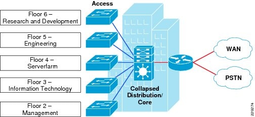
Figure 2-5 shows a two-tier LAN network design example for a medium enterprise LAN where the distribution and core layers are collapsed into a single layer.
Figure 2-5 Two-Tier Network Design Example
If using the small-scale collapsed campus core design, the enterprise network architect must understand the network and application demands so that this design ensures a hierarchical, modular, resilient, and flexible LAN network.
Medium Enterprise LAN Design Models
Both LAN design models (three-tier and two-tier) have been developed with the following considerations:
•
•
•
•
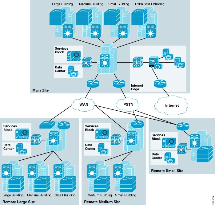
As shown in Figure 2-6,multiple campuses can co-exist within a single medium enterprise system that offers various academic programs.
Figure 2-6 Medium Enterprise LAN Design Model
Depending on the remote campus office facility, the number of employees and the networked devices in remote campuses may be equal to or less than the main site. Campus network designs for the remote campus may require adjusting based on overall campus capacity.
Using high-speed WAN technology, all the remote medium enterprise campuses interconnect to a centralized main site that provides shared services to all the employees independent of their physical location. The WAN design is discussed in greater detail in the next chapter, but it is worth mentioning in the LAN section because some remote sites may integrate LAN and WAN functionality into a single platform. Collapsing the LAN and WAN functionality into a single Cisco platform can provide all the needed requirements for a particular remote site as well as provide reduced cost to the overall design, as discussed in more detail in the following section.
Table 2-1 shows a summary of the LAN design models as they are applied in the overall medium enterprise network design.
Main Site Network Design
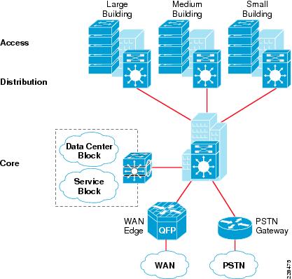
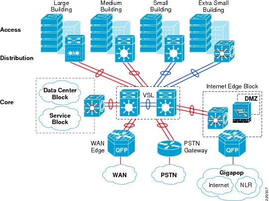
The main site in the medium enterprise design consists of a centralized hub campus location that interconnects several sizes of remote campuses to provide end-to-end shared network access and services, as shown in Figure 2-7.
Figure 2-7 Main Site Reference Design
The main site typically consists of various sizes of building facilities and various organization department groups. The network scale factor in the main site is higher than the remote campus site, and includes end users, IP-enabled endpoints, servers, and security and network edge devices. Multiple buildings of various sizes exist in one location, as shown in Figure 2-8.
Figure 2-8 Main Site Reference Design
The three-tier LAN design model for the main site meets all key technical aspects to provide a well-structured and strong network foundation. The modularity and flexibility in a three-tier LAN design model allows easier expansion and integration in the main site network, and keeps all network elements protected and available.
To enforce external network access policy for each end user, the three-tier model also provides external gateway services to the employees for accessing the Internet.
Note
Remote Large Campus Site Design
From the location size and network scale perspective, the remote large site is not much different from the main site. Geographically, it can be distant from the main campus site and requires a high-speed WAN circuit to interconnect both campuses. The remote large site can also be considered as an alternate campus to the main campus site, with the same common types of applications, endpoints, users, and network services. Similar to the main site, separate WAN devices are recommended to provide application delivery and access to the main site, given the size and number of employees at this location.
Similar to the main site, Cisco recommends the three-tier LAN design model for the remote large site campus, as shown in Figure 2-9.
Figure 2-9 Remote Large Campus Site Reference Design
Remote Medium Campus Site Design
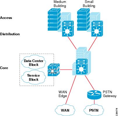
Remote medium campus locations differ from a main or remote large site campus in that there are less buildings with distributed organization departments. A remote medium campus may have a fewer number of network users and endpoints, thereby reducing the need to build a similar campus network to that recommended for main and large campuses. Because there are fewer employees and networked devices at this site as compared to the main or remote large site campus sites, the need for a separate WAN device may not be necessary. A remote medium campus network is designed similarly to a three-tier large campus LAN design. All the LAN benefits are achieved in a three-tier design model as in the main and remote large site campus, and in addition, the platform chosen in the core layer also serves as the WAN edge, thus collapsing the WAN and core LAN functionality into a single platform. Figure 2-10 shows the remote medium campus in more detail.
Figure 2-10 Remote Medium Campus Site Reference Design
Remote Small Campus Network Design
The remote small campus is typically confined to a single building that spans across multiple floors with different academic departments. The network scale factor in this design is reduced compared to other large campuses. However, the application and services demands are still consistent across the medium enterprise locations.
In such smaller scale campus network deployments, the distribution and core layer functions can collapse into the two-tier LAN model without compromising basic network demands. Before deploying a collapsed core and distribution layer in the remote small campus network, considering all the scale and expansion factors prevents physical network re-design, and improves overall network efficiency and manageability.
WAN bandwidth requirements must be assessed appropriately for this remote small campus network design. Although the network scale factor is reduced compared to other larger campus locations, sufficient WAN link capacity is needed to deliver consistent network services to employees. Similar to the remote medium campus location, the WAN functionality is also collapsed into the LAN functionality. A single Cisco platform can provide collapsed core and distribution LAN layers. This design model is recommended only in smaller locations, and WAN traffic and application needs must be considered. Figure 2-11 shows the remote small campus in more detail.
Figure 2-11 Remote Small Campus Site Reference Design
Multi-Tier LAN Design Models for Medium Enterprise
The previous section discussed the recommended LAN design model for each medium enterprise location. This section provides more detailed design guidance for each tier in the LAN design model. Each design recommendation is optimized to keep the network simplified and cost-effective without compromising network scalability, security, and resiliency. Each LAN design model for a medium enterprise location is based on the key LAN layers of core, distribution, and access.
Campus Core Layer Network Design
As discussed in the previous section, the core layer becomes a high-speed intermediate transit point between distribution blocks in different premises and other devices that interconnect to the data center, WAN, and Internet edge.
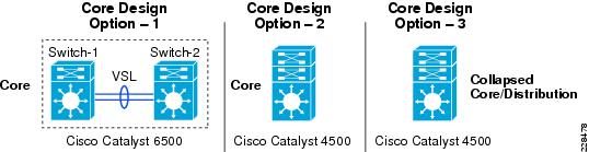
Similarly to choosing a LAN design model based on a location within the medium enterprise design, choosing a core layer design also depends on the size and location within the design. Three core layer design models are available, each of which is based on either the Cisco Catalyst 6500-E Series or the Cisco Catalyst 4500-E Series Switches. Figure 2-12 shows the three core layer design models.
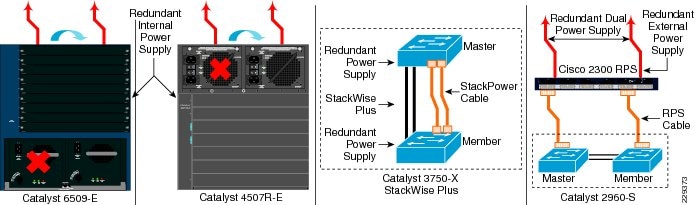
Figure 2-12 Core Layer Design Models for Medium Enterprises
Each design model offers consistent network services, high availability, expansion flexibility, and network scalability. The following sections provide detailed design and deployment guidance for each model as well as where they fit within the various locations of the medium enterprise design.
Core Layer Design Option 1—Cisco Catalyst 6500-E-Based Core Network
Core layer design option 1 is specifically intended for the main and remote large site campus locations. It is assumed that the number of network users, high-speed and low-latency applications (such as Cisco TelePresence), and the overall network scale capacity is common in both sites and thus, similar core design principles are required.
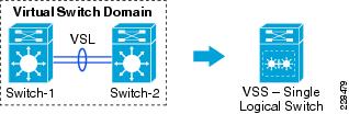
Core layer design option 1 is based on Cisco Catalyst 6500 Series switches using the Cisco Virtual Switching System (VSS), which is a software technology that builds a single logical core system by clustering two redundant core systems in the same tier. Building a VSS-based network changes network design, operation, cost, and management dramatically. Figure 2-13 shows the physical and operational view of VSS.
Figure 2-13 VSS Physical and Operational View
To provide end-to-end network access, the core layer interconnects several other network systems that are implemented in different roles and service blocks. Using VSS to virtualize the core layer into a single logical system remains transparent to each network device that interconnects to the VSS-enabled core. The single logical connection between core and the peer network devices builds a reliable, point-to-point connection that develops a simplified network topology and builds distributed forwarding tables to fully use all resources. Figure 2-14 shows a reference VSS-enabled core network design for the main campus site.
Figure 2-14 VSS-Enabled Core Network Design
Note
Core Layer Design Option 2—Cisco Catalyst 4500-E-Based Campus Core Network
Core layer design option 2 is intended for a remote medium-sized campus and is built on the same principles as for the main and remote large site campus locations. The size of this remote site may not be large, and it is assumed that this location contains distributed building premises within the remote medium campus design. Because this site is smaller in comparison to the main and remote large site campus locations, a fully redundant, VSS-based core layer design may not be necessary. Therefore, core layer design option 2 was developed to provide a cost-effective alternative while providing the same functionality as core layer design option 1. Figure 2-15 shows the remote medium campus core design option in more detail.
Figure 2-15 Remote Medium Campus Core Network Design
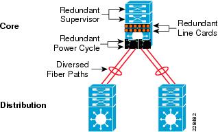
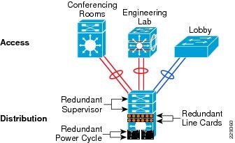
The cost of implementing and managing redundant systems in each tier may introduce complications in selecting the three-tier model, especially when network scale factor is not too high. This cost-effective core network design provides protection against various types of hardware and software failure and offers sub-second network recovery. Instead of a redundant node in the same tier, a single Cisco Catalyst 4500-E Series Switch can be deployed in the core role and bundled with 1+1 redundant in-chassis network components. The Cisco Catalyst 4500-E Series modular platform is a one-size platform that helps enable the high-speed core backbone to provide uninterrupted network access within a single chassis. Although a fully redundant, two-chassis design using VSS as described in core layer option 1 provides the greatest redundancy for large-scale locations, the redundant supervisors and line cards of the Cisco Catalyst 4500-E provide adequate redundancy for smaller locations within a single platform. Figure 2-16 shows the redundancy of the Cisco Catalyst 4500-E Series in more detail.
Figure 2-16 Highly Redundant Single Core Design Using the Cisco Catalyst 4500-E Platform
This core network design builds a network topology that has similar common design principles to the VSS-based campus core in core layer design option 1. The future expansion from a single core to a dual VSS-based core system becomes easier to deploy, and helps retain the original network topology and the management operation. This cost-effective single resilient core system for a medium-size enterprise network meets the following four key goals:
•
•
•
•
Core Layer Design Option 3—Cisco Catalyst 4500-E-Based Collapsed Core Campus Network
Core layer design option 3 is intended for the remote small campus network that has consistent network services and applications service-level requirements but at reduced network scale. The remote small campus is considered to be confined within a single multi-story building that may span academic departments across different floors. To provide consistent services and optimal network performance, scalability, resiliency, simplification, and cost-effectiveness in the small campus network design must not be compromised.
As discussed in the previous section, the remote small campus has a two-tier LAN design model, so the role of the core system is merged with the distribution layer. Remote small campus locations have consistent design guidance and best practices defined for main, remote large site, and remote medium-sized campus cores. However, for platform selection, the remote medium campus core layer design must be leveraged to build this two-tier campus core.
Single highly resilient Cisco Catalyst 4500-E switches with a Cisco Sup6L-E supervisor must be deployed in a centralized collapsed core and distribution role that interconnects to wiring closet switches, a shared service block, and a WAN edge router. The cost-effective supervisor version supports key technologies such as robust QoS, high availability, security, and much more at a lower scale, making it an ideal solution for small-scale network designs. Figure 2-17 shows the remote small campus core design in more detail.
Figure 2-17 Core Layer Option 3 Collapsed Core/Distribution Network Design in Remote Small Campus Location
Campus Distribution Layer Network Design
The distribution or aggregation layer is the network demarcation boundary between wiring-closet switches and the campus core network. The framework of the distribution layer system in the medium enterprise design is based on best practices that reduce network complexities and accelerate reliability and performance. To build a strong campus network foundation with the three-tier model, the distribution layer has a vital role in consolidating networks and enforcing network edge policies.
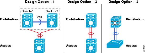
The following the core layer design options in different campus locations, the distribution layer design provides consistent network operation and configuration tools to enable various network services. Three simplified distribution layer design options can be deployed in main or remote campus locations, depending on network scale, application demands, and cost, as shown in Figure 2-18. Each design model offers consistent network services, high availability, expansion flexibility, and network scalability.
Figure 2-18 Distribution Layer Design Model Options
Distribution Layer Design Option 1—Cisco Catalyst 6500-E Based Distribution Network
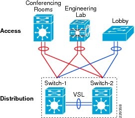
Distribution layer design option 1 is intended for main campus and remote large site campus locations, and is based on Cisco Catalyst 6500-E Series switches using the Cisco VSS, as shown in Figure 2-19.
Figure 2-19 VSS-Enabled Distribution Layer Network Design
The distribution block and core network operation changes significantly when redundant Cisco Catalyst 6500-E Series switches are deployed in VSS mode in both the distribution and core layers. Clustering redundant distribution switches into a single logical system with VSS introduces the following technical benefits:
•
•
•
•
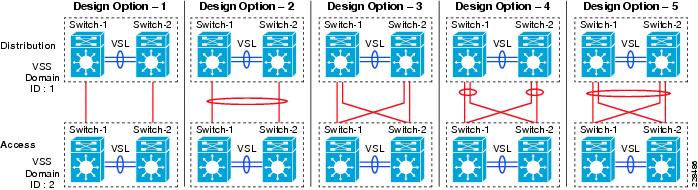
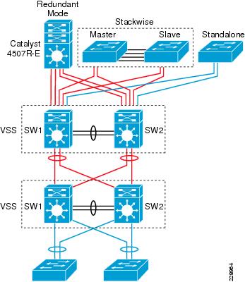
Deploying VSS mode in both the distribution layer switch and core layer switch provides numerous technology deployment options that are not available when not using VSS. Designing a common core and distribution layer option using VSS provides greater redundancy and is able to handle the amount of traffic typically present in the main and remote large site campus locations. Figure 2-20 shows five unique VSS domain interconnect options. Each variation builds a unique network topology that has a direct impact on steering traffic and network recovery.
Figure 2-20 Core/Distribution Layer Interconnection Design Considerations
The various core/distribution layer interconnects offer the following:
•
•
•
•
•
Distribution Layer Design Option 2—Cisco Catalyst 4500-E-Based Distribution Network
Two cost-effective distribution layer models have been designed for the medium-sized and small-sized buildings within each campus location that interconnect to the centralized core layer design option and distributed wiring closet access layer switches. Both models are based on a common physical LAN network infrastructure and can be chosen based on overall network capacity and distribution block design. Both distribution layer design options use a cost-effective single and highly resilient Cisco Catalyst 4500-E as an aggregation layer system that offers consistent network operation like a VSS-enabled distribution layer switch. The Cisco Catalyst 4500-E Series provides the same technical benefits of VSS for a smaller network capacity within a single Cisco platform. The two Cisco Catalyst 4500-E-based distribution layer options are shown in Figure 2-21.
Figure 2-21 Two Cisco Catalyst 4500-E-Based Distribution Layer Options
The hybrid distribution block must be deployed with the next-generation supervisor Sup6-E module. Implementing redundant Sup6-Es in the distribution layer can interconnect access layer switches and core layer switches using a single point-to-point logical connection. This cost-effective and resilient distribution design option leverages core layer design option 2 to take advantage of all the operational consistency and architectural benefits.
Alternatively, the multilayer distribution block option requires the Cisco Catalyst 4500-E Series Switch with next-generation supervisor Sup6L-E deployed. The Sup6L-E supervisor is a cost-effective distribution layer solution that meets all network foundation requirements and can operate at moderate capacity, which can handle a medium-sized enterprise distribution block.
This distribution layer network design provides protection against various types of hardware and software failure, and can deliver consistent sub-second network recovery. A single Catalyst 4500-E with multiple redundant system components can be deployed to offer 1+1 in-chassis redundancy, as shown in Figure 2-22.
Figure 2-22 Highly Redundant Single Distribution Design
Distribution layer design option 2 is intended for the remote medium-sized campus locations, and is based on the Cisco Catalyst 4500-E Series switches. Although the remote medium and the main and remote large site campus locations share similar design principles, the remote medium campus location is smaller and may not need a VSS-based redundant design. Fortunately, network upgrades and expansion become easier to deploy using distribution layer option 2, which helps retain the original network topology and the management operation. Distribution layer design option 2 meets the following goals:
•
•
•
•
Distribution Layer Design Option 3—Cisco Catalyst 3750-X StackWise-Based Distribution Network
Distribution layer design option 3 is intended for a very small building with a limited number of wiring closet switches in the access layer that connects remote classrooms or and office network with a centralized core, as shown in Figure 2-23.
Figure 2-23 Cisco StackWise Plus-enabled Distribution Layer Network Design
While providing consistent network services throughout the campus, a number of network users and IT-managed remote endpoints can be limited in this building. This distribution layer design option recommends using the Cisco Catalyst 3750-X StackWise Plus Series platform for the distribution layer switch.
The fixed-configuration Cisco Catalyst 3750-X Series switch is a multilayer platform that supports Cisco StackWise Plus technology to simplify the network and offers flexibility to expand the network as it grows. With Cisco StackWise Plus technology, multiple Catalyst 3750-X can be stacked into a high-speed backplane stack ring to logically build as a single large distribution system. Cisco StackWise Plus supports up to nine switches into single stack ring for incremental network upgrades, and increases effective throughput capacity up to 64 Gbps. The chassis redundancy is achieved via stacking, in which member chassis replicate the control functions with each member providing distributed packet forwarding. This is achieved by stacked group members acting as a single virtual Catalyst 3750-X switch. The logical switch is represented as one switch by having one stack member act as the master switch. Thus, when failover occurs, any member of the stack can take over as a master and continue the same services. It is a 1:N form of redundancy where any member can become the master. This distribution layer design option is ideal for the remote small campus location.
Campus Access Layer Network Design
The access layer is the first tier or edge of the campus, where end devices such as PCs, printers, cameras, Cisco TelePresence, and so on attach to the wired portion of the campus network. It is also the place where devices that extend the network out one more level, such as IP phones and wireless access points (APs), are attached. The wide variety of possible types of devices that can connect and the various services and dynamic configuration mechanisms that are necessary, make the access layer one of the most feature-rich parts of the campus network. Not only does the access layer switch allow users to access the network, the access layer switch must provide network protection so that unauthorized users or applications do not enter the network. The challenge for the network architect is determining how to implement a design that meets this wide variety of requirements, the need for various levels of mobility, the need for a cost-effective and flexible operations environment, while being able to provide the appropriate balance of security and availability expected in more traditional, fixed-configuration environments. The next-generation Cisco Catalyst switching portfolio includes a wide range of fixed and modular switching platforms, each designed with unique hardware and software capability to function in a specific role.
Enterprise campuses may deploy a wide range of network endpoints. The campus network infrastructure resources operate in shared service mode, and include IT-managed devices such as Cisco TelePresence and non-IT-managed devices such as employee laptops. Based on several endpoint factors such as function and network demands and capabilities, two access layer design options can be deployed with campus network edge platforms, as shown in Figure 2-24.
Figure 2-24 Access Layer Design Models
Access Layer Design Option 1—Modular/StackWise Plus/FlexStack Access Layer Network
Access layer design option 1 is intended to address the network scalability and availability for the IT-managed critical voice and video communication network edge devices. To accelerate user experience and campus physical security protection, these devices require low latency, high performance, and a constant network availability switching infrastructure. Implementing a modular, Cisco StackWise Plus and latest Cisco's innovation FlexStack-capable platform provides flexibility to increase network scale in the densely populated campus network edge.
The Cisco Catalyst 4500-E with supervisor Sup6E-L can be deployed to protect devices against access layer network failure. Cisco Catalyst 4500-E Series platforms offer consistent and predictable sub-second network recovery using NSF/SSO technology to minimize the impact of outages on enterprise business and IT operation.
The Cisco Catalyst 3750-X Series is the alternate Cisco switching platform in this design option. Cisco StackWise Plus technology provides flexibility and availability by clustering multiple Cisco Catalyst 3750-X Series Switches into a single high-speed stack ring that simplifies operation and allows incremental access layer network expansion. The Cisco Catalyst 3750-X Series leverages EtherChannel technology for protection during member link or stack member switch failure.
The Catalyst 2960-S with FlexStack technology is Cisco's latest innovation in access-layer tier. Based on StackWise Plus architecture, the FlexStack design is currently supported on Layer-2 Catalyst 2960-S Series switches. Following to the Catalyst 3750-X StackWise Plus success, the Catalyst 2960-S model offers high availability, increased port-density with unified single control-plane and management to reduce the cost for small enterprise network. However the architecture of FlexStack on Catalyst 2960-S series platform differs from StackWise Plus. The Cisco FlexStack is comprised with hardware module and software capabilities. The FlexStack module must be installed on each Catalyst 2960-S switches that are intended to be deployed in stack-group. Cisco FlexStack module is hot-swappable module providing flexibility to deploy FlexStack without impacting business network operation.
Access Layer Design Option 2—Fixed Configuration Access Layer Network
This entry-level access layer design option is widely chosen for enterprise environments. The fixed configuration Cisco Catalyst switching portfolio supports a wide range of access layer technologies that allow seamless service integration and enable intelligent network management at the edge.
The next-generation fixed configuration Cisco Catalyst 3560-X and Catalyst 2960 Series is a commonly deployed platform for wired network access that can be in a mixed configuration with critical devices such as Cisco IP Phones and non-mission critical endpoints such as library PCs, printers, and so on. For non-stop network operation during power outages, the Catalyst 3560-X must be deployed with an internal or external redundant power supply solution using the Cisco RPS 2300. Increasing aggregated power capacity allows flexibility to scale with enhanced power-over-Ethernet (PoE+) on a per-port basis. With its wire-speed 10G uplink forwarding capacity, this design reduces network congestion and latency to significantly improve application performance.
For a campus network, the Cisco Catalyst 3560-X is an alternate switching solution for the multilayer distribution block design option discussed in the previous section. The Cisco Catalyst 3560-X Series Switches offer limited software feature support that can function only in a traditional Layer 2 network design. To provide a consistent end-to-end enhanced user experience, the Cisco Catalyst 2960-S supports critical network control services to secure the network edge, intelligently provide differentiated services to various class-of-service traffic, as well as simplified management. The Cisco Catalyst must leverage the 1G dual uplink ports to interconnect the distribution system for increased bandwidth capacity and network availability.
Both design options offer consistent network services at the campus edge to provide differentiated, intelligent, and secured network access to trusted and untrusted endpoints. The distribution options recommended in the previous section can accommodate both access layer design options.
Deploying Medium Enterprise Network Foundation Services
After each tier in the model has been designed, the next step for the medium enterprise design is to establish key network foundation services. Regardless of the application function and requirements that medium enterprises demand, the network must be designed to provide a consistent user experience independent of the geographical location of the application. The following network foundation design principles or services must be deployed in each campus location to provide resiliency and availability for all users to obtain and use the applications the medium enterprise offers:
•
•
•
•
•
•
Design guidance for each of these six network foundation services are discussed in the following sections, including where they are deployed in each tier of the LAN design model, the campus location, and capacity.
Implementing LAN Network Infrastructure
The preceding sections provided various design options for deploying the Cisco Catalyst platform in multi-tier centralized main campus and remote campus locations. The Medium Enterprise Reference network is designed with consistency to build simplified network topology for easier operation, management, and troubleshooting independent of campus location. Depending on network size, scalability, and reliability requirements, the Medium Enterprise Reference design applies the following common set of Cisco Catalyst platforms in different campus network layers:
•
•
•
•
This subsection focuses on building the initial LAN network infrastructure setup to bring the network up to the stage to start establishing network protocol communication with the peer devices. The deployment and configuration guidelines remain consistent for each recommended Catalyst platform independent of their network role. Advanced network services implementation and deployment guidelines will be explained in subsequent section.
Deploying Cisco Catalyst 6500-E in VSS Mode
All the VSS design principles and foundational technologies defined in this subsection remains consistent when the Cisco Catalyst 6500-E is deployed in VSS mode at campus core or distribution layer.
Prior to enabling the Cisco Catalyst 6500-E in VSS mode, enterprise network administrator must adhere to Cisco recommended best practices to take complete advantage of virtualized system and minimize the network operation downtime when migration is required in a production network. Migrating VSS from the standalone Catalyst 6500-E system requires multiple pre and post-migration steps to deploy virtual-system that includes building virtual-system itself and migrating the existing standalone network configuration to operate in virtual-system environment. Refer to the following document for step-by-step migration procedure:
http://www.cisco.com/en/US/products/ps9336/products_tech_note09186a0080a7c74c.shtml
This subsection is divided into the following categories that provide guidance for deploying mandatory steps and procedure in implementing VSS and its components in campus distribution and core.
•
•
•
•
•
VSS Identifiers
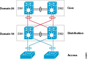
This is the first premigration step to be implemented on two standalone Cisco Catalyst 6500-E in the same campus tier that are planned to be clustered into a single logical entity. Cisco VSS defines the following two types of physical node identifiers to distinguish remote node within the logical entity as well as to set logical VSS domain identity to uniquely identify beyond the single VSS domain boundary.
Domain ID
Defining the domain identifier (ID) is the initial step in creating a VSS with two physical chassis. The domain ID value ranges from 1 to 255. Virtual Switch Domain (VSD) is comprised with two physical switches and they must be configured with common domain ID. When implementing VSS in multi-tier campus network design, the unique domain ID between different VSS pair will prevent network protocol conflicts and allow simplified network operation, troubleshooting, and management.
Switch ID
In current software version, each VSD supports up to two physical switches to build a logical virtual switch. The switch ID value is 1 or 2. Within VSD, each physical chassis must be uniquely configure switch-ID to successfully deploy VSS. Post VSS migration when two physical chassis is clustered, from the control-plane and management plane perspective, it will create single large system; therefore, all the distributed physical interfaces between two chassis are automatically appended with the switch ID (i.e., <switch-id>/<slot#>/<port#> or TenGigabitEthernet 1/1/1. The significance of the switch ID remains within VSD and all the interfaces ID associated to the switch ID will be retained independent of control-plane ownership. See Figure 2-25.
Figure 2-25 VSS Domain and Switch ID
The following simple configuration shows how to configure VSS domain ID and switch ID:
Standalone Switch 1:
VSS-SW1(config)# switch virtual domain 20VSS-SW1(config-vs-domain)# switch 1Standalone Switch 2:
VSS-SW2(config)# switch virtual domain 20VSS-SW2(config-vs-domain)# switch 2Switch Priority
During both virtual-switch bootup processes, the switch priority is negotiated between both virtual switches to determine the control-plane ownership. Virtual-switch configured with high priority takes the control-plane ownership while the low priority switch boots up in redundant mode. The default switch priority is 100, the lower switch ID is a tie-breaker when both virtual-switch node are deployed with default settings.
Cisco recommends deploying both virtual-switch nodes with identical hardware and software to take full advantage of distributed forwarding architecture with centralized control and management plane. The control-plane operation is identical on either of the virtual-switch nodes. Modifying the default switch priority is an optional setting since either of the virtual-switch can provide transparent operation to network and the user.
Virtual Switch Link
To cluster two physical chassis into single a logical entity, the Cisco VSS technology enables the capability to extend various types of single-chassis internal system components to multi-chassis level. Each virtual-switch must be deployed with the direct physical links and extend the backplane communication boundary over the special links known as Virtual-Switch Link (VSL).
VSL can be considered as Layer 1 physical links between two virtual-switch nodes and is designed to not operate any network control protocols. Therefore, the VSL links cannot establish network protocol adjacencies and are excluded when building the network topology tables. With the customized traffic engineering on VSL, it is tailored to carry the following major traffic categories:
•
–
–
•
–
–
•
–
–
–
Using EtherChannel technology, the VSS software design provides the flexibility to increase on-demand VSL bandwidth capacity and to protect the network stability during the VSL link failure or malfunction.
The following sample configuration shows how to configure VSL EtherChannel:
Standalone Switch 1:
VSS-SW1(config)# interface Port-Channel 1VSS-SW1(config-if)# switch virtual link 1VSS-SW1(config)# interface range Ten 1/1 , Ten 5/4VSS-SW1(config-if)# channel-group 1 mode onStandalone Switch 2:
VSS-SW2(config)# interface Port-Channel 2VSS-SW2(config-if)# switch virtual link 2VSS-SW2(config)# interface range Ten 1/1 , Ten 5/4VSS-SW2(config-if)# channel-group 2 mode onVSL Design Consideration
Implementing VSL EtherChannel is a simple task; however, the VSL design may require proper design with high reliability, availability, and optimized. Deploying VSL requires careful planning to keep system virtualization intact during VSS system component failure on either virtual-switch node. The strategy for reliable VSL design requires the following three categories of planning:
•
•
•
VSL Links Diversification
Complete VSL link failure may break the system virtualization and create network instability during VSL link failure. Designing VSL link redundancy through diverse physical paths on both systems prevents network instability, reduces single point of failure conditions and optimizes bootup process.
All the traffic traverses over the VSL are encoded with special encapsulation header, hence VSL protocols is not designed to operate all Catalyst 6500-E supported linecard module. The next-generation specialized Catalyst 6500-E 10G based supervisor and linecard modules are fully capable and equipped with modern hardware ASICs to build VSL communication. VSL EtherChannel can bundle 10G member-links with any of following next-generate hardware modules:
•
•
•
Figure 2-26 shows an example of how to build VSL EtherChannel with multiple diverse physical fiber paths from supervisor 10G uplink ports and the VSL-capable 10G hardware modules.
Figure 2-26 Recommended VSL Links Design
Deploying VSL with multiple diversified VSL-link design offers the following benefits:
•
•
•
•
•
VSL Bandwidth Capacity
From each virtual-switch node, VSL EtherChannel can bundle up to 8 physical member-links. Therefor, VSL can be bundled up to 80G of bandwidth capacity, the requirement on exact capacity may truly depend on number of the following factors:
•
•
•
•
For an optimal traffic load-sharing between VSL member-links, it is recommended to bundle VSL member-link in the power of 2 (i.e., 2, 4, and 8).
VSL QoS
The network infrastructure and the application demands of next-generation enterprise networks have tremendous amount of dependencies on the strong and resilient network for constant network availability and on-demand bandwidth allocation to provide services compromising performance. Cisco VSS is designed with application intelligence and automatically enables QoS on VSL interface to provide bandwidth and resource allocation for different class-of-service traffic.
The QoS implementation on VSL EtherChannel operates in restricted mode as it carries critical inter-chassis backplane traffic. Independent of global QoS settings, the VSL member-links are automatically configured with system generated QoS settings to protect different class of applications. To retain system stability, the inter-switch VSLP protocols the QoS settings are fine tuned to protect high priority traffic with different thresholds even during VSL link congestion.
To deploy VSL in non-blocking mode and increase the queue depth, the Sup720-10G uplink ports can be configured in one of the following two QoS modes:
•
•
Implementing 10G mode may assist in increasing the number of transmit and receive queue depth level; however, restricted VSL QoS prevents reassigning different class-of-service traffic in different queues. Primary benefit in implementing 10G-only mode is to deploy VSL port in non-blocking mode to dedicate complete 10G bandwidth on port. Deploying VSS network based on Cisco's recommendation significantly reduces VSL link utilization, thus minimizing the need to implement 10G-only mode and using all 1G ports for other network connectivities (i.e., out-of-band network management port).
Unified Control-Plane
Deploying redundant supervisor with common hardware and software components into single standalone Cisco Catalyst 6500-E platform automatically enables the Stateful Switch Over (SSO) capability to provide in-chassis supervisor redundancy in highly redundant network environment. The SSO operation on active supervisor holds control-plane ownership and communicates with remote Layer 2 and Layer 3 neighbors to build distributed forwarding information. SSO-enabled active supervisor is tightly synchronized with standby supervisor with several components (protocol state-machine, configuration, forwarding information, etc.). As a result, if an active supervisor fails, a hot-standby supervisor takes over control-plane ownership and initializes protocol graceful-recovery with peer devices. During network protocol graceful-recovery process the forwarding information remains non-disrupted to continue nonstop packet switching in hardware.
Leveraging the same SSO and NSF technology, the Cisco VSS supports inter-chassis SSO redundancy by extending the supervisor redundancy capability from single-chassis to multi-chassis level. Cisco VSS uses VSL EtherChannel as a backplane path to establish SSO communication between active and hot-standby supervisor deployed in separate physical chassis. Entire virtual-switch node gets reset during abnormal active or hot-standby virtual-switch node failure. See Figure 2-27.
Figure 2-27 Inter-Chassis SSO Operation in VSS
To successfully establish SSO communication between two virtual-switch nodes, the following criteria must match between both virtual-switch node:
•
•
•
•
•
During the bootup process, the SSO synchronization checks all the above criteria with remote virtual-system. If any of the criteria fails to match, it will force the virtual-switch node to boot in RPR or cold-standby state that cannot synchronize protocol and forwarding information.
VSL Dual-Active Detection and Recovery
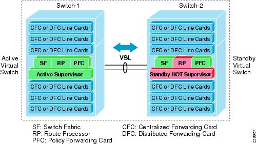
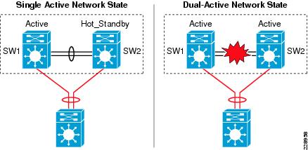
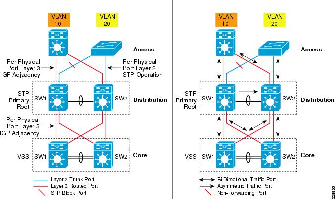
The preceding section described VSL EtherChannel functions as extended backplane link that enables system virtualization by transporting inter-chassis control traffic, network control plane and user data traffic. The state machine of the unified control-plane protocols and distributed forwarding entries gets dynamically synchronized between the two virtual-switch nodes. Any fault triggered on VSL component leads to a catastrophic instability in VSS domain and beyond. The virtual-switch member that assumes the role of hot-standby keeps constant communication with the active switch. The role of the hot-standby switch is to assume the active role as soon as it detects a loss of communication with its peer via all VSL links without the operational state information of the remote active peer node. Such network condition is known an dual-active, where both virtual switches get split with common configuration and takes control plane ownership. The network protocols detect inconsistency and instability when VSS peering devices detect two split systems claiming the same addressing and identifications. Figure 2-28 depicts the state of campus topology in a single active-state and during dual-active state.
Figure 2-28 Single Active and Dual-Active Campus Topology
The system virtualization gets impacted during the dual-active network state and splits the single virtual system into two identical Layer 2/3 system. This condition that can destabilize the campus network communication with two split system advertising duplicate information. To prevent such network instability, Cisco VSS introduces the following two methods to rapidly detect dual-active condition and recover the situation by isolating the old active virtual-switch from network operation before the network gets destabilized:
•
–
–
–
–
•
All dual-active detection protocol and methods can be implemented in parallel. As depicted in Figure 2-29, in a VSS network deployment peering with Cisco Catalyst platforms, Cisco recommends deploying Fast-Hello and PAgP+ methods for rapid detection, to minimize network topology instability, and to retain application performance intact.
Figure 2-29 Recommended Dual-Active Detection Method
The following sample configuration illustrates implementing both methods:
•
cr23-VSS-Core(config)#interface range Gig1/5/1 , Gig2/5/1cr23-VSS-Core(config-if-range)# dual-active fast-hello! Following logs confirms fast-hello adjacency is established on! both virtual-switch nodes.%VSDA-SW1_SP-5-LINK_UP: Interface Gi1/5/1 is now dual-active detection capable%VSDA-SW2_SPSTBY-5-LINK_UP: Interface Gi2/5/1 is now dual-active detection capablecr23-VSS-Core#show switch virtual dual-active fast-helloFast-hello dual-active detection enabled: YesFast-hello dual-active interfaces:Port Local State Peer Port Remote State-----------------------------------------------------------------------------Gi1/5/1 Link up Gi2/5/1 Link up•
Enabling or disabling dual-active trusted mode on L2/L3 MEC requires MEC to be in administration shutdown state. Prior to implementing trust settings, network administrator must plan for downtime to provision PAgP+-based dual-active configuration settings:
cr23-VSS-Core(config)#int range Port-Channel 101 - 102cr23-VSS-Core(config-if-range)#shutdowncr23-VSS-Core(config)#switch virtual domain 20cr23-VSS-Core(config-vs-domain)#dual-active detection pagp trust channel-group 101cr23-VSS-Core(config-vs-domain)#dual-active detection pagp trust channel-group 102cr23-VSS-Core(config)#int range Port-Channel 101 - 102cr23-VSS-Core(config-if-range)#no shutdowncr23-VSS-Core#show switch virtual dual-active pagpPAgP dual-active detection enabled: YesPAgP dual-active version: 1.1Channel group 101 dual-active detect capability w/nbrsDual-Active trusted group: YesDual-Active Partner Partner PartnerPort Detect Capable Name Port VersionTe1/1/2 Yes cr22-6500-LB Te2/1/2 1.1Te1/3/2 Yes cr22-6500-LB Te2/1/4 1.1Te2/1/2 Yes cr22-6500-LB Te1/1/2 1.1Te2/3/2 Yes cr22-6500-LB Te1/1/4 1.1Channel group 102 dual-active detect capability w/nbrsDual-Active trusted group: YesDual-Active Partner Partner PartnerPort Detect Capable Name Port VersionTe1/1/3 Yes cr24-4507e-MB Te4/2 1.1Te1/3/3 Yes cr24-4507e-MB Te3/1 1.1Te2/1/3 Yes cr24-4507e-MB Te4/1 1.1Te2/3/3 Yes cr24-4507e-MB Te3/2 1.1Virtual Routed MAC
The MAC address allocation for the interfaces does not change during a switchover event when the hot-standby switch takes over as the active switch. This avoids gratuitous ARP updates (MAC address changed for the same IP address) from devices connected to VSS. However, if both chassis are rebooted at the same time and the order of the active switch changes (the old hot-standby switch comes up first and becomes active), then the entire VSS domain will use that switch's MAC address pool. This means tat the interface will inherit a new MAC address, which will trigger gratuitous ARP updates to all Layer-2 and Layer-3 interfaces. Any networking device connected one hop away from the VSS (and any networking device that does not support gratuitous ARP), will experience traffic disruption until the MAC address of the default gateway/interface is refreshed or timed out. To avoid such a disruption, Cisco recommends using the configuration option provided with the VSS in which the MAC address for Layer-2 and Layer-3 interfaces is derived from the reserved pool. This takes advantage of the virtual-switch domain identifier to form the MAC address. The MAC addresses of the VSS domain remain consistent with the usage of virtual MAC addresses, regardless of the boot order.
The following configuration illustrates how to configure virtual routed MAC address for Layer 3 interface under switch-virtual configuration mode:
cr23-VSS-Core(config)#switch virtual domain 20cr23-VSS-Core(config-vs-domain)#mac-address use-virtualDeploying Cisco Catalyst 4500-E
In a mid-size medium enterprise campus network, it is recommended to deploy single highly redundant Cisco Catalyst 4500-E Series platform in the different campus network tiers-access, distribution, core. Cisco Catalyst 4500-E Series switches is a multi-slots modular and scalable and high-speed resilient platform. Single Catalyst 4500-E Series platform in medium enterprise design is build with multiple redundant hardware components to develop consistent network topology as Catalyst 6500-E VSS based large network design. For Catalyst 4500-E in-chassis supervisor redundancy, the network administrators must consider Catalyst 4507R-E or 4510R-E slot chassis to accommodate redundant supervisors and use remaining for LAN network modules.
Cisco Catalyst 4500-E Series supports wide-range of supervisor modules designed for high-performance Layer 2 and Layer 3 network. This reference design recommends deploying next-generation Sup6E and Sup6L-E that supports next-generation hardware switching capabilities, scalability, and performance for various types application and services deployed in campus network.
Implementing Redundant Supervisor
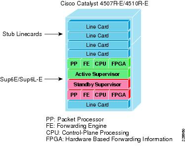
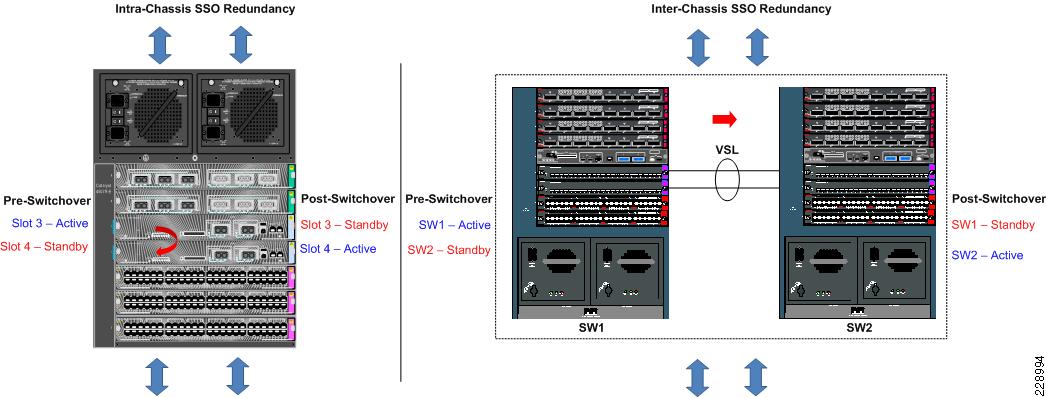
Cisco Catalyst 4507R-E supports intra-chassis or single-chassis supervisor redundancy with dual-supervisor support. Implementing single Catalyst 4507R-E in highly resilient mode at various campus layer with multiple redundant hardware components will protect against different types of abnormal failures. This reference design guide recommends deploying redundant Sup6E or Sup6L-E supervisor module to deploy full high-availability feature parity. Mid-size core or distribution layer Cisco Catalyst 4507R-E Series platform currently do not support inter-chassis supervisor and node redundancy with VSS technology. Therefore, implementing intra-chassis supervisor redundancy and initial network infrastructure setup will be simplified for medium and small size campus network. Figure 2-30 illustrates Cisco Catalyst 4500-E-based intra-chassis SSO and NSF capability.
Figure 2-30 Intra-Chassis SSO Operation
During bootup process, the SSO synchronization checks various criteria to assure both supervisors can provide consistent and transparent network services during failure event. If any of the criteria fails to match, it forces the standby supervisor to boot in RPR or cold-standby state which cannot synchronize protocol and forwarding information from active supervisor. The following sample configuration illustrates how to implement SSO mode on Catalyst 4507R-E and 4510R-E chassis deployed with Sup6E and Sup6L-E redundant supervisors:
cr24-4507e-MB#config tcr24-4507e-MB (config)#redundancycr24-4507e-MB (config-red)#mode ssocr24-4507e-MB#show redundancy statesmy state = 13 - ACTIVEpeer state = 8 - STANDBY HOT< snippet >Sup6L-E Enhancement
Starting in IOS Release 12.2(53)SG, Cisco introduced new Catalyst 4500 - Sup6L-E supervisor module that is designed and built on the next-generation supervisor Sup6E architecture. As a cost-effective solution, the Sup6L-E supervisor is built with reduced system resources, but also addresses several types of key business and technical challenges for mid- to small-scale size Layer-2 network design.
Initial IP-based IOS Release for Sup6L-E supports SSO capability for multiple types of Layer 2 protocols. To extend its high availability and enterprise-class Layer 3 feature-parity support on Sup6L-E supervisor, it is recommended to deploy IOS Release 12.2(53)SG2 software version with Enterprise license.
Note
Deploying Supervisor Uplinks
Every supported supervisor module in Catalyst 4500-E supports different types of uplink ports for core network connectivity. Each Sup6E and Sup6L-E supervisor module supports up two 10G or can deployed as four different 1G uplinks using Twin-Gigabit converters. To build high speed low-latency campus backbone network, it is recommended to leverage and deploy 10G uplinks to accommodate various types of bandwidth demanding network application operating in the network.
Cisco Catalyst 4500-E Series supervisors are designed with unique architecture to provide constant network availability and reliability during supervisor reset. Even during supervisor switchover or administrative reset events, the state-machines of all deployed uplinks remains operation and with centralized forwarding architecture it continue to switch packets without impacting any time-sensitive application like Cisco TelePresence. Such unique architecture protects bandwidth capacity while administrative supervisor switchover is to upgrade IOS software or during abnormal software triggers supervisor reset.
Sup6E Uplink Port Design
Non-Redundant Mode
In non-redundant mode, there is a single supervisor module deployed in Catalyst 4500-E chassis. In non-redundant mode, by default both uplink physical ports can be deployed in 10G or 1G with Twin-Gigabit converters. Each port operates in non-blocking state and can switch traffic at the wire-rate performance.
Redundant Mode
In recommended redundant mode, Catalyst 4507R-E chassis is deployed with dual supervisor. To provide wire-rate switching performance, by default port-group 1 from active and hot-standby supervisor are in active mode and put port-group 2 in the in-active state. The default configuration can be modified by changing Catalyst 4500-E backplane settings to sharing mode. The shared backplane mode enables operation of port-group 2 of both supervisors. Note that sharing the 10G backplane ASIC between two 10G port do not increase switching capacity, it creates 2:1 oversubscription. If the upstream device is deployed with chassis-redundancy (i.e., Catalyst 6500-E VSS), then it is highly recommended to deploy all four uplink ports for the following reasons:
•
•
•
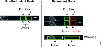
Figure 2-31 summarizes the uplink port support on Sup6E model depends on non-redundant and redundant deployment scenario.
Figure 2-31 Catalyst 4500-E Sup6E Uplink Mode
The following sample configuration provides guideline to modify default backplane settings on Catalyst 4507R-E platform deployed with Sup6E supervisors in redundant mode. The new backplane settings will be effective only after complete chassis gets reset; therefore, it is important to plan the downtime during this implementation:
cr24-4507e-MB#config tcr24-4507e-MB(config)#hw-module uplink mode shared-backplane!A 'redundancy reload shelf' or power-cycle of chassis is required! to apply the new configurationcr24-4507e-MB#show hw-module uplinkActive uplink mode configuration is Shared-backplanecr24-4507e-MB#show hw-module mod 3 port-groupModule Port-group Active Inactive----------------------------------------------------------------------3 1 Te3/1-2 Gi3/3-6cr24-4507e-MB#show hw-module mod 4 port-groupModule Port-group Active Inactive----------------------------------------------------------------------4 1 Te4/1-2 Gi4/3-6Sup6L-E Uplink Port Design
The Sup6L-E uplink port function same as Sup6E in non-redundant mode. However, in redundant mode the hardware design of Sup6L-E differs from Sup6E—currently does not support shared backplane mode that allow using all uplink ports actively. The Catalyst 4507R-E deployed with Sup6L-E may use 10G uplink of port group 1 from active and standby supervisor when the upstream device is a single, highly redundant Catalyst 4507R-E chassis. If the upstream device is deployed with chassis-redundancy, (i.e., Cisco VSS), then it is recommended to build full-mesh network design between each supervisor and virtual-switch node. For such design, the network administrator must leverage the existing WS-4606 Series 10G linecard to build full-mesh uplink. Figure 2-32 illustrates the deployment guideline for highly resilient Catalyst 4507R-E-based Sup6L-E uplink.
Figure 2-32 Catalyst 4500-E Sup6L-E Uplink Mode
Deploying Cisco Catalyst 3750-X StackWise Plus
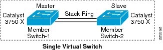
The next-generation Cisco Catalyst 3750-X switches can be deployed in StackWise mode using special stack cable that develops bidirectional physical ring topology. Up to nine switches can be integrated into a single stack ring that offers robust distributed forwarding architecture and unified single control and management plane. Device level redundancy in StackWise mode is achieved via stacking multiple switches using the Cisco StackWise Plus technology. Single switch from the stack ring is selected in master role that manages centralized control-plane process while keeping all member switches in member role. Cisco StackWise Plus solution is designed based on 1:N redundancy option. Master switch election in stack ring is determined based on internal protocol negotiation. During the active master switch failure, the new master is selected based on reelection process that takes place internally through the stack ring. See Figure 2-33.
Figure 2-33 Cisco StackWise Plus Switching Architecture
Since Cisco StackWise Plus solution is developed with high redundancy, it offers unique centralized control and management plane with forwarding architecture design. To logically appear as a single virtual switch, the master switch manages complete management-plane and Layer-3 control-plane operations (i.e., IP Routing, CEF, PBR, etc.). Depending on the implemented network protocols, the master switch communicates with rest of the Layer 3 network through stack ring and dynamically develops the best path global routing and updates local hardware with forwarding information.
Unlike centralized Layer-3 management function on master switch, the Layer-2 network topology development is completely based on distributed design. Each member switch in the stack ring dynamically discovers MAC entry from the local port and use internal stack ring network to synchronize MAC address table on each member switch in the stack ring. Table 2-2 lists the network protocols that are designed to operate in centralized versus distributed model in Cisco StackWise Plus architecture.
Using stack ring as a backplane communication path, master switch updates the Layer-3 forwarding information base (FIB) to each member-switch in the stack ring. Synchronizing common FIB in member switch will develop distributed forwarding architecture. Each member switch performs local forwarding physical path lookup to transmit the frame instead of having master switch performing forwarding path lookup, which may cause traffic hair-pinning problem.
SSO Operation in 3750-EX StackWise Plus
Cisco StackWise Plus solution offers network and device resiliency with distributed forwarding, but the control plane is not designed like 1+1 redundant design. This is because Cisco Catalyst 3750-X StackWise switch is not an SSO-capable platform that can synchronize control-plane state-machines to a standby switch in the ring. However, it can be configured in NSF-capable mode to gracefully recover from the network during master switch failure. Therefore, when the master switch failure occurs, all the Layer 3 function that is primarily deployed on the uplink ports may get disrupted until new master election occurs and reforms Layer 3 adjacency. Although the new master switch in the stack ring identification is done in range of 0.7 to 1 second, the amount of time for rebuilding the network and forwarding topology depends on the protocol function and scalability.
To prevent Layer 3 disruption in the network caused by master switch failure, the determined master switch with the higher switch priority can be isolated from the uplink Layer 3 EtherChannel bundle path and use physical ports from switches in member role. With the Non-Stop Forwarding (NSF) capabilities in the Cisco StackWise Plus architecture, this network design helps to decrease major network downtime during master switch failure.
Implementing StackWise Mode
As described earlier, Cisco Catalyst 3750-E switch dynamically detects and provision member-switches in the stack ring without any extra configuration. For planned deployment, network administrator can pre-provision the switch in the ring with the following configuration in global configuration mode:
cr36-3750x-xSB(config)#switch 3 provision WS-C3750E-48PDcr36-3750x-xSB#show running-config | include interface GigabitEthernet3/interface GigabitEthernet3/0/1interface GigabitEthernet3/0/2Switch Priority
The centralized control-plane and management plane is managed by the master switch in the stack. By default, the master switch selection within the ring is performed dynamically by negotiating several parameters and capabilities between each switch within the stack. Each StackWise-capable member-switch is by default configured with switch priority 1.
cr36-3750x-xSB#show switchSwitch/Stack Mac Address : 0023.eb7b.e580H/W CurrentSwitch# Role Mac Address Priority Version State------------------------------------------------------------------------------------------ ---------------* 1 Master 0023.eb7b.e580 1 0 Ready2 Member 0026.5284.ec80 1 0 ReadyAs described in previous section, the Cisco StackWise architecture is not SSO-capable. This means all the centralized Layer-3 functions must be reestablished with the neighbor switch during a master-switch outage. To minimize the control-plane impact and improve network convergence, the Layer 3 uplinks should be diverse, originating from member switches, instead of the master switch. The default switch priority must be increased manually after identifying the master switch and switch number. The new switch priority becomes effective after switch reset.
cr36-3750x-xSB (config)#switch 1 priority 15Changing the Switch Priority of Switch Number 1 to 15cr36-3750x-xSB (config)#switch 2 priority 14Changing the Switch Priority of Switch Number 2 to 14cr36-3750x-xSB # show switchSwitch/Stack Mac Address : 0023.eb7b.e580H/W CurrentSwitch# Role Mac Address Priority Version State------------------------------------------------------------------------------------------ ----------1 Master 0023.eb7b.e580 15 0 Ready* 2 Member 0026.5284.ec80 14 0 ReadyStack-MAC Address
To provide a single unified logical network view in the network, the MAC addresses of Layer-3 interfaces on the StackWise (physical, logical, SVIs, port channel) are derived from the Ethernet MAC address pool of the master switch in the stack. All the Layer-3 communication from the StackWise switch to the endpoints (like IP phone, PC, servers, and core network system) is based on the MAC address pool of the master switch.
cr36-3750x-xSB#show switchSwitch/Stack Mac Address : 0023.eb7b.e580H/W CurrentSwitch# Role Mac Address Priority Version State------------------------------------------------------------------------------------------ ----------1 Master 0023.eb7b.e580 15 0 Ready* 2 Member 0026.5284.ec80 14 0 Readycr36-3750s-xSB #show version. . .Base ethernet MAC Address : 00:23:EB:7B:E5:80. . .To prevent network instability, the old MAC address assignments on Layer-3 interfaces can be retained even after the master switch fails. The new active master switch can continue to use the MAC addresses assigned by the old master switch, which prevents ARP and routing outages in the network. The default stack-mac timer settings must be changed in Catalyst 3750-X StackWise switch mode using the global configuration CLI mode as shown below:
cr36-3750x-xSB (config)#stack-mac persistent timer 0cr36-3750x-xSB #show switchSwitch/Stack Mac Address : 0026.5284.ec80Mac persistency wait time: IndefiniteH/W CurrentSwitch# Role Mac Address Priority Version State------------------------------------------------------------------------------------------ ----------1 Master 0023.eb7b.e580 15 0 Ready* 2 Member 0026.5284.ec80 14 0 ReadyDeploying Cisco Catalyst 3560-X and 2960-S FlexStack
The Medium Enterprise Reference design recommends deploying fixed configuration Cisco Catalyst 3560-X and 2960 Series platform at the campus network edge. The hardware architecture of access-layer fixed configuration is standalone and non-modular in design. These switches are designed to go above traditional access-layer switching function to provide robust next-generation network services (i.e., edge security, PoE+ EnergyWise, etc.).
Cisco Catalyst 3560-X and 2960 Series platform do not support StackWise technology, therefore, these platforms are ready to deploy with a wide-range of network services at the access-layer. All recommended access-layer features and configuration will be explained in following relevant sections.
The access-layer Cisco Catalyst 2960-S Series switches can be stacked using Cisco FlexStack technology that allows stacking up to four switches into single stack ring using special properietary cable. Cisco FlexStack leverages several architecture components from Cisco Catalyst 3750-X StackWise Plus. However it offers flexibility to upgrade hardware capability in standalone Cisco Catalyst 2960-S series platform to support FlexStack with hot-swappable FlexStack module. The FlexStack module supports dual on-board StackPort each design to support upto 10G switching capacity. The StackPorts on FlexStack module is not a network ports hence it does not run any Layer 2 network protocols, i.e. STP, to develop virtual-switch environment each participating Cisco Catalyst 2960-S in stack-ring runs FlexStack protocol to keep protocols, ports and forwarding information synchronized within the ring. The port configuration and QoS configuration StackPorts are preset and cannot be modified by user, it is design to minimize the network impact due to misconfiguration. From an operational perspective Cisco Catalyst 2960-S FlexStack technology is identical as Cisco Catalyst 3750-X StackWise Plus. Therefore, all the deployment guidelines and best practices defined in "Deploying Cisco Catalyst 3750-X StackWise Plus" section must be leverage to deploy Cisco Catalyst 2960-S FlexStack in the campus access-layer.
Designing EtherChannel Network
In this reference design, multiple parallel physical paths are recommended to build highly scalable and resilient medium enterprise network design. Without optimizing the network configuration, by default each interfaces requires network configuration, protocol adjacencies and forwarding information to load-share traffic and provide network redundancy.
The reference architecture of medium enterprise network is design is built upon small- to mid-size enterprise-class network. Depending on the network applications, scalability, and performance requirement, it offers wide-range of campus network designs, platform and technology deployment options in different campus locations and building premises. Each campus network design offers the following set of operation benefits:
•
•
•
•
Diversified EtherChannel Physical Design
As a general best practice to build resilient network designs, it is highly recommended to interconnect all network systems with full-mesh diverse physical paths. Such network design automatically creates multiple parallel paths to provide load-sharing capabilities and path redundancy during network fault events. Deploying single physical connection from a standalone single system to separate redundant upstream systems creates a "V" shape physical network design instead non-recommended partial-mesh "square" network design.
Cisco recommends building full-mesh fiber path between each Layer 2 or Layer 3 operating in standalone, redundant (dual-supervisor) or virtual systems (Cisco VSS and StackWise Plus. Independent of network tier and platform role, this design principle is applicable to all systems across campus network. Figure 2-34 demonstrates recommended deployment physical network design model for various Catalyst platforms.
Figure 2-34 Designing Diverse Full-mesh Network Topology
Deploying diverse physical network design with redundant mode standalone or the virtual-system running single control-plane will require extra network design tuning to gain all EtherChannel benefits. Without designing the campus network with EtherChannel technology, the individual redundant parallel paths will create network operation state depicted in Figure 2-35. Such network design cannot leverage distributed forwarding architecture and increase operational and troubleshooting complexities. Figure 2-35 demonstrates the default network design with redundant and complex control-plane operation with under-utilized forwarding plane design.
Figure 2-35 Non-optimized Campus Network Design
The design in Figure 2-35 suffers from the following challenges for different network modes:
•
•
•
Implementing campus wide MEC or EtherChannel across all the network platforms is the solution for all of the above challenges. Bundling multiple parallel paths into single logical connection builds single loop-free, point-to-point topology that helps to eliminate all protocol-driven forwarding restrictions and program hardware for distributed forwarding to fully use all network resources.
EtherChannel Fundamentals
In a standalone EtherChannel mode, multiple and diversified member-links are physically connected in parallel between two same physical systems. All the key network devices in the Medium Enterprise Reference design support EtherChannel technology. Independent of campus location and the network layer-campus, data center, WAN/Internet edge, all the EtherChannel fundamentals and configuration guideline described in this section remain consistent.
Multi-Chassis EtherChannel Fundamentals
Cisco's Multi-Chassis EtherChannel (MEC) technology is a breakthrough innovation that lifts up barrier to create logical point-to-point EtherChannel by distributing physical connection to each highly resilient virtual-switch node in the VSS domain. Deploying Layer 2 or Layer 3 MEC with VSS introduces the following benefits:
•
•
•
•
•
Implementing EtherChannel
In a standalone EtherChannel mode, multiple and diversified member-links are physically connected in parallel between two same physical systems. All the key network devices in the medium enterprise network design support EtherChannel technology. Independent of campus location and the network layer—campus, data center, WAN/Internet edge, all the EtherChannel fundamentals and configuration guideline described in this section remain consistent.
Port-Aggregation Protocols
The member-links of EtherChannel must join the port-channel interface using Cisco PAgP+ or industry standard LACP port-aggregation protocols. Both protocols are designed to provide identical benefits. Implementing these protocols provides the following additional benefits:
•
•
•
•
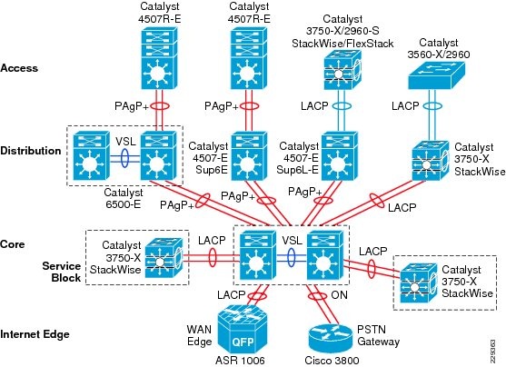
Figure 2-36 Network-Wide Port-Aggregation Protocol Deployment Guidelines
Port-aggregation protocol support varies on various types of Cisco platforms; therefore, depending on each end of EtherChannel device types, Cisco recommends deploying the port-channel settings specified in Table 2-3.
Table 2-3 MEC Port-Aggregation Protocol Recommendation
PAgP+
Desirable
Desirable
Operational
LACP
Active
Active
Operational
None 1
ON
ON
Operational
1 None or Static Mode EtherChannel configuration must be deployed in exceptional cases when remote node do not support either of the port-aggregation protocols. To prevent network instability, network administrator must implement static mode port-channel with special attention that assures no configuration in-compatibility between bundling member-link ports.
The implementation guidelines to deploy EtherChannel and MEC in Layer 2 or Layer 3 mode are simple and consistent. The following sample configuration provides a guidance to implement single point-to-point Layer-3 MEC from diverse physical ports in different module slots that physically resides in two virtual-switch chassis to a single redundant mode, standalone Catalyst 4507R-E system:
•
cr23-VSS-Core(config)#interface Port-channel 102cr23-VSS-Core(config-if)# ip address 10.125.0.14 255.255.255.254! Bundling single MEC diversed physical ports and module on per node basis.cr23-VSS-Core(config)#interface range Ten1/1/3 , Ten1/3/3 , Ten2/1/3 , Ten2/3/3cr23-VSS-Core(config-if-range)#channel-protocol pagpcr23-VSS-Core(config-if-range)#channel-group 102 mode desirablecr23-VSS-Core#show etherchannel 102 summary | inc Te102 Po102(RU) PAgP Te1/1/3(P) Te1/3/3(P) Te2/1/3(P) Te2/3/3(P)cr23-VSS-Core#show pagp 102 neighbor | inc TeTe1/1/3 cr24-4507e-MB 0021.d8f5.45c0 Te4/2 27s SC 10001Te1/3/3 cr24-4507e-MB 0021.d8f5.45c0 Te3/1 28s SC 10001Te2/1/3 cr24-4507e-MB 0021.d8f5.45c0 Te4/1 11s SC 10001Te2/3/3 cr24-4507e-MB 0021.d8f5.45c0 Te3/2 11s SC 10001•
cr24-4507e-MB (config)#interface Port-channel 1cr24-4507e-MB (config-if)# ip address 10.125.0.15 255.255.255.254! Bundling single EtherChannel diversed on per physical ports and per supervisor basis.cr24-4507e-MB (config)#interface range Ten3/1 - 2 , Ten4/1 - 2cr24-4507e-MB (config-if-range)#channel-protocol pagpcr24-4507e-MB (config-if-range)#channel-group 1 mode desirablecr24-4507e-MB #show etherchannel 101 summary | inc Te1 Po1 (RU) PAgP Te3/1(P) Te3/2(P) Te4/1(P) Te4/2(P)cr24-4507e-MB#show pagp 1 neighbor | inc TeTe3/1 cr23-VSS-Core 0200.0000.0014 Te1/3/3 26s SC 660001Te3/2 cr23-VSS-Core 0200.0000.0014 Te2/3/3 15s SC 660001Te4/1 cr23-VSS-Core 0200.0000.0014 Te2/1/3 25s SC 660001Te4/2 cr23-VSS-Core 0200.0000.0014 Te1/1/3 11s SC 660001EtherChannel Load-Sharing
The numbers of applications and their function in campus network design becomes highly variable, especially when the network is provided as a common platform for business operation, campus security and open accessibility to the users. It becomes important for the network to become more intelligence-aware with deep packet-inspection and load-share the traffic by fully using all network resources.
Fine tuning EtherChannel and MEC add an extra computing intelligence in the network to make protocol-aware egress forwarding decision between multiple local member-links paths. For each traffic flow, such tuning optimizes the egress path-selection procedure with multiple levels of variable information that are originated by the source host (i.e., Layer 2 to Layer 4). EtherChannel load-balancing method supports varies on Cisco Catalyst platforms. Table 2-4 summarizes the currently supported EtherChannel load-balancing methods.
Implementing EtherChannel Load-Sharing
EtherChannel load-sharing is based on a polymorphic algorithm. On per-protocol basis, load sharing is done based on source XOR destination address or port from Layer 2 to 4 header and ports. For the higher granularity and optimal utilization of each member-link port, an EtherChannel can intelligently load-share egress traffic using different algorithms.
All Cisco Catalyst 29xx-S, 3xxx-X, and 4500-E switching must be tuned with optimal EtherChannel load-sharing capabilities similar to the following sample configuration:
cr24-4507e-MB(config)#port-channel load-balance src-dst-ipcr24-4507e-MB#show etherchannel load-balanceEtherChannel Load-Balancing Configuration:src-dst-ipImplementing MEC Load-Sharing
The next-generation Catalyst 6500-E Sup720-10G supervisor introduces more intelligence and flexibility to load-share traffic with upto 13 different traffic patterns. Independent of virtual-switch role, each node in VSD uses same polymorphic algorithm to load-share egress Layer 2 or Layer 3 traffic across different member-links from local chassis. When computing the load-sharing hash, each virtual-switch node includes local physical ports of MEC instead remote switch ports; this customized load-sharing is design to prevent traffic reroute over the VSL. It is recommended to implement the following MEC load-sharing configuration in the global configuration mode:
cr23-VSS-Core(config)#port-channel load-balance src-dst-mixed-ip-portcr23-VSS-Core#show etherchannel load-balanceEtherChannel Load-Balancing Configuration:src-dst-mixed-ip-port vlan included
Note
MEC Hash Algorithm
Like MEC load sharing, the hash algorithm is computed independently by each virtual-switch to perform load share via its local physical ports. Traffic-load share is defined based on number of internal bits allocated to each local member-link ports. Cisco Catalyst 6500-E system in VSS mode assigns 8 bits to every MEC, 8-bit can be represented as 100 percent switching load. Depending on number of local member-link ports in an MEC bundle, the 8-bit hash is computed and allocated to each port for optimal load-sharing result. Like standalone network design, VSS supports the following EtherChannel hash algorithms:
•
•
When deploying full-mesh V-shape network VSS-enabled campus core network, it is recommended to modify default MEC hash algorithm from default settings as shown in the following sample configuration:
cr23-VSS-Core(config)#port-channel hash-distribution adaptiveModifying MEC hash algorithm to adaptive mode requires the system to internally reprogram hash result on each MEC. Therefore, plan for additional downtime to make new configuration effective.
cr23-VSS-Core(config)#interface Port-channel 101cr23-VSS-Core(config-if)#shutdowncr23-VSS-Core(config-if)#no shutdowncr23-VSS-Core#show etherchannel 101 detail | inc HashLast applied Hash Distribution Algorithm: AdaptiveNetwork Addressing Hierarchy
Developing a structured and hierarchical IP address plan is as important as any other design aspect of the medium enterprise network to create an efficient, scalable, and stable network design. Identifying an IP addressing strategy for the network for the entire medium enterprise network design is essential.
Note
The following are key benefits of using hierarchical IP addressing:
•
–
–
•
–
–
–
–
•
–
–
–
–
Network Foundational Technologies for LAN Design
In addition to a hierarchical IP addressing scheme, it is also essential to determine which areas of the medium enterprise design are Layer 2 or Layer 3 to determine whether routing or switching fundamentals need to be applied. The following applies to the three layers in a LAN design model:
•
•
•
The recommended routing or switching scheme of each layer is discussed in the following sections.
Designing the Core Layer Network
Because the core layer is a Layer 3 network, routing principles must be applied. Choosing a routing protocol is essential, and routing design principles and routing protocol selection criteria are discussed in the following subsections.
Routing Design Principles
Although enabling routing functions in the core is a simple task, the routing blueprint must be well understood and designed before implementation, because it provides the end-to-end reachability path of the enterprise network. For an optimized routing design, the following three routing components must be identified and designed to allow more network growth and provide a stable network, independent of scale:
•
•
•
Routing Protocol Selection Criteria
The criteria for choosing the right protocol vary based on the end-to-end network infrastructure. Although all the routing protocols that Cisco IOS currently supports can provide a viable solution, network architects must consider all the following critical design factors when selecting the right routing protocol to be implemented throughout the internal network:
•
•
•
•
Cisco IOS supports a wide range of routing protocols, such as Routing Information Protocol (RIP) v1/2, Enhanced Interior Gateway Routing Protocol (EIGRP), Open Shortest Path First (OSPF), and Intermediate System-to-Intermediate System (IS-IS). However, Cisco recommends using EIGRP or OSPF for this network design. EIGRP is a popular version of an Interior Gateway Protocol (IGP) because it has all the capabilities needed for small to large-scale networks, offers rapid network convergence, and above all is simple to operate and manage. OSPF is popular link-state protocol for large-scale enterprise and service provider networks. OSPF enforces hierarchical routing domains in two tiers by implementing backbone and non-backbone areas. The OSPF area function depends on the network connectivity model and the role of each OSPF router in the domain. OSPF can scale higher but the operation, configuration, and management might become too complex for the medium enterprise LAN network infrastructure.
Other technical factors must be considered when implementing OSPF in the network, such as OSPF router type, link type, maximum transmission unit (MTU) considerations, designated router (DR)/backup designated router (BDR) priority, and so on. This document provides design guidance for using simplified EIGRP in the medium enterprise campus and WAN network infrastructure.
Note
Designing an End-to-End EIGRP Routing Network
EIGRP is a balanced hybrid routing protocol that builds neighbor adjacency and flat routing topology on a per autonomous system (AS) basis. Cisco recommends considering the following three critical design tasks before implementing EIGRP in the medium enterprise LAN core layer network:
•
Figure 2-37 Sample End-to-End EIGRP Routing Design in Medium Enterprise LAN Network
Implementing EIGRP Routing Protocol
The following sample configuration provides deployment guideline for implement EIGRP routing protocol on all Layer-3 network devices into a single Autonomous System (AS):
cr23-VSS-Core(config)#router eigrp 100cr23-VSS-Core(config-router)# network 10.0.0.0cr23-VSS-Core(config-router)# eigrp router-id 10.125.200.254cr23-VSS-Core(config-router)# no auto-summarycr23-VSS-Core#show ip eigrp neighborsEIGRP-IPv4 neighbors for process 100H Address Interface Hold Uptime SRTT RTO Q Seq(sec) (ms) Cnt Num7 10.125.0.13 Po101 12 3d16h 1 200 0 620 10.125.0.15 Po102 10 3d16h 1 200 0 5031 10.125.0.17 Po103 11 3d16h 1 200 0 52...cr23-VSS-Core#show ip route eigrp | inc /16|/20|0.0.0.010.0.0.0/8 is variably subnetted, 41 subnets, 5 masksD 10.126.0.0/16 [90/3072] via 10.125.0.23, 08:33:16, Port-channel106D 10.125.128.0/20 [90/3072] via 10.125.0.17, 08:33:15, Port-channel103D 10.125.96.0/20 [90/3072] via 10.125.0.13, 08:33:18, Port-channel101D 10.125.0.0/16 is a summary, 08:41:12, Null0...D*EX 0.0.0.0/0 [170/515072] via 10.125.0.27, 08:33:20, Port-channel108•
–
cr23-VSS-Core(config)#router eigrp 100cr23-VSS-Core(config-router)# passive-interface defaultcr23-VSS-Core(config-router)# no passive-interface Port-channel101cr23-VSS-Core(config-router)# no passive-interface Port-channel102<snippet>–
cr23-VSS-Core(config)#key chain eigrp-keycr23-VSS-Core(config-keychain)# key 1cr23-VSS-Core(config-keychain-key)#key-string <password>cr23-VSS-Core(config)#interface range Port-Channel 101 - 108cr23-VSS-Core(config-if-range)# ip authentication mode eigrp 100 md5cr23-VSS-Core(config-if-range)# ip authentication key-chain eigrp 100 eigrp-key•
Figure 2-38 EIGRP Route Aggregator Design
The following configuration must be applied on each EIGRP route aggregator system as depicted in Figure 2-38. EIGRP route summarization must be implemented on upstream logical port-channel interface to announce single prefix from each block.
cr22-6500-LB(config)#interface Port-channel100cr22-6500-LB(config-if)# ip summary-address eigrp 100 10.125.96.0 255.255.240.0cr22-6500-LB#show ip protocols...Address Summarization:10.125.96.0/20 for Port-channel100<snippet>cr22-6500-LB#s ip route | inc Null0D 10.125.96.0/20 is a summary, 3d16h, Null0•
Designing the Campus Distribution Layer Network
This section provides design guidelines for deploying various types of Layer 2 and Layer 3 technology in the distribution layer. Independent of which implemented distribution layer design model is deployed, the deployment guidelines remain consistent in all designs.
Because the distribution layer can be deployed with both Layer 2 and Layer 3 technologies, the following two network designs are recommended:
•
•
Designing the Multilayer Network
A multilayer network is a traditional, simple, and widely deployed scenario, regardless of network scale. The access layer switches in the campus network edge interface with various types of endpoints and provide intelligent Layer 1/2 services. The access layer switches interconnect to distribution switches with the Layer 2 trunk, and rely on the distribution layer aggregation switch to perform intelligent Layer 3 forwarding and to set policies and access control.
There are the following three design variations to build a multilayer network; all variations must be deployed in a V-shape physical network design and must be built to provide a loop-free topology:
•
•
•
Figure 2-39 shows the three design variations for the multilayer network.
Figure 2-39 Multilayer Design Variations
Cisco recommends that the hybrid multilayer access-distribution block design use a loop-free network topology, and span a few VLANs that require such flexibility, such as the management VLAN.
The following sample configuration provides guideline to deploy several types of multilayer network components for hybrid multilayer access-distribution block. All the configuration and best practices remains consistent and can deployed independent of Layer 2 platform type and campus location:
VTP
VLAN Trunking Protocol (VTP) is a Cisco proprietary Layer -messaging protocol that manages the addition, deletion, and renaming of VLANs on a network-wide basis. Cisco's VTP simplifies administration in a switched network. VTP can be configured in three modes—server, client, and transparent. It is recommended to deploy VTP in transparent mode, set the VTP domain name and change the mode to the transparent mode as follows:
cr22-3750-LB(config)#vtp domain CCVE-LBcr22-3750-LB(config)#vtp mode transparentcr22-3750-LB(config)#vtp version 2cr22-3750-LB#show vtp statusVTP Version capable : 1 to 3VTP version running : 2VTP Domain Name : CCVE-LBVLAN
cr22-3750-LB(config)#vlan 101cr22-3750-LB(config-vlan)#name Untrusted_PC_VLANcr22-3750-LB(config)#vlan 102cr22-3750-LB(config-vlan)#name Lobby_IP_Phone_VLANcr22-3750-LB(config)#vlan 900cr22-3750-LB(config-vlan)#name Mgmt_VLANcr22-3750-LB#show vlan | inc 101|102|900101 Untrusted_PC_VLAN active Gi1/0/1102 Lobby_IP_Phone_VLAN active Gi1/0/2900 Mgmt_VLAN activeImplementing Layer 2 Trunk
In a typical campus network design, a single access switch will be deployed with more than singleVLAN, for example a Data VLAN and a Voice VLAN. The Layer-2 network connection between the distribution and access device is a trunk interface. VLAN tag is added to maintain logical separation between VLANS across the trunk. It is recommended to implement 802.1Q trunk encapsulation in static mode instead of negotiating mode, to improve the rapid link bring-up performance.
Enabling the Layer-2 trunk on a port-channel automatically enables communication for all of the active VLANs between the access and distribution. This may create an adverse impact in the large scale network, the access-layer switch may receive traffic flood destined to another access switch. Hence it is important to limit traffic on Layer-2 trunk ports by statically allowing the active VLANS to ensure efficient and secure network performance. Allowing only assigned VLANs on a trunk port automatically filters rest.
By default on Cisco Catalyst switches, the native VLAN on each Layer 2 trunk port is VLAN 1, and cannot be disabled or removed from VLAN database. The native VLAN remains active on all access switches Layer 2 ports. The default native VLAN must be properly configured to avoid several security risks—Attack, worm and virus or data theft. Any malicious traffic originated in VLAN 1 will span across the access-layer network. With a VLAN-hopping attack it is possible to attack a system which does not reside in VLAN 1. Best practice to mitigate this security risk is to implement a unused and unique VLAN ID as a native VLAN on the Layer-2 trunk between the access and distribution switch. For example, configure VLAN 801 in the access-switch and in the distribution switch. Then change the default native VLAN setting in both the switches. Thereafter, VLAN 801 must not be used anywhere for any purpose in the same access-distribution block.
The following is the configuration example to implement Layer-2 trunk, filter VLAN list and configure the native-VLAN to prevent attacks and optimize port channel interface. When the following configurations are applied on port-channel interface (i.e., Port-Channel 1), they are automatically inherited on each bundled member-link (i.e., Gig1/0/49 and Gig1/0/50):
Access-Layer
cr22-3750-LB(config)#vlan 801cr22-3750-LB(config-vlan)#name Hopping_VLANcr22-3750-LB(config)#interface Port-channel1cr22-3750-LB(config-if)#description Connected to cr22-6500-LBcr22-3750-LB(config-if)#switchportcr22-3750-LB(config-if)#switchport trunk encapsulation dot1qcr22-3750-LB(config-if)#switchport trunk native vlan 801cr22-3750-LB(config-if)#switchport trunk allowed vlan 101-110,900cr22-3750-LB(config-if)#switchport mode trunkcr22-3750-LB#show interface port-channel 1 trunkPort Mode Encapsulation Status Native vlanPo1 on 802.1q trunking 801Port Vlans allowed on trunkPo1 101-110,900Port Vlans allowed and active in management domainPo1 101-110,900Port Vlans in spanning tree forwarding state and not prunedPo1 101-110,900Spanning-Tree in Multilayer Network
Spanning Tree (STP) is a Layer-2 protocol that prevents logical loops in switched networks with redundant links. The medium enterprise LAN network design uses Etherchannel or MEC (point-to-point logical Layer-2 bundle) connection between access-layer and distribution switch which inherently simplifies the STP topology and operation. In this point-to-point network design, the STP operation is done on a logical port, therefore, it will be assigned automatically in forwarding state.
Over the years, the STP protocols have evolved into the following versions:
•
•
•
The following is the example configuration for enabling STP in multilayer network:
Distribution-Layer
cr22-6500-LB(config)#spanning-tree mode rapid-pvstcr22-6500-LB #show spanning-tree summary | inc mode!Switch is in rapid-pvst modeAccess-Layer
cr22-3750-LB(config)#spanning-tree mode rapid-pvstHardening Spanning-Tree Toolkit
Ensuring a loop-free topology is critical in a multilayer network design. Spanning-Tree Protocol (STP) dynamically develops a loop-free multilayer network topology that can compute the best forwarding path and provide redundancy. Although STP behavior is deterministic, it is not optimally designed to mitigate network instability caused by hardware miswiring or software misconfiguration. Cisco has developed several STP extensions to protect against network malfunctions, and to increase stability and availability. All Cisco Catalyst LAN switching platforms support the complete STP toolkit suite that must be enabled globally on individual logical and physical ports of the distribution and access layer switches.
Figure 2-40 shows an example of enabling various STP extensions on distribution and access layer switches in all campus sites.
Figure 2-40 Protecting Multilayer Network with Cisco STP Toolkit
Note
Designing the Routed Access Network
Routing functions in the access layer network simplify configuration, optimize distribution performances, and provide end-to-end troubleshooting tools. Implementing Layer 3 functions in the access layer replaces Layer 2 trunk configuration to a single point-to-point Layer 3 interface with a collapsed core system in the aggregation layer. Pushing Layer 3 functions one tier down on Layer 3 access switches changes the traditional multilayer network topology and forwarding development path. Implementing Layer 3 functions in the access switch does not require any physical or logical link reconfiguration; the access-distribution block can be used, and is as resilient as in the multilayer network design. Figure 2-41 shows the differences between the multilayer and routed access network designs, as well as where the Layer 2 and Layer 3 boundaries exist in each network design.
Figure 2-41 Layer 2 and Layer 3 Boundaries for Multilayer and Routed Access Network Design
Routed-access network design enables Layer 3 access switches to perform Layer 2 demarcation point and provide Inter-VLAN routing and gateway function to the endpoints. The Layer 3 access switches makes more intelligent, multi-function and policy-based routing and switching decision like distribution-layer switches.
Although Cisco VSS and a single redundant distribution design are simplified with a single point-to-point EtherChannel, the benefits in implementing the routed access design in medium enterprises are as follows:
•
•
•
•
Enabling Layer 3 functions in the access-distribution block must follow the same core network designs as mentioned in previous sections to provide network security as well as optimize the network topology and system resource utilization:
•
•
•
Implementing Routed Access in Access-Distribution Block
Cisco IOS configuration to implement Layer 3 routing function on the Catalyst access-layer switch remains consistent. Refer to EIGRP routing configuration and best practices defined in Designing End-to-End EIGRP Network section to routing function in access-layer switches.
EIGRP creates and maintains a single flat routing topology network between EIGRP peers. Building a single routing domain in a large-scale campus core design allows for complete network visibility and reachability that may interconnect multiple campus components, such as distribution blocks, services blocks, the data center, the WAN edge, and so on.
In the three- or two-tier deployment models, the Layer 3 access switch must always have single physical or logical forwarding to a distribution switch. The Layer 3 access switch dynamically develops the forwarding topology pointing to a single distribution switch as a single Layer 3 next hop. Because the distribution switch provides a gateway function to rest of the network, the routing design on the Layer 3 access switch can be optimized with the following two techniques to improve performance and network reconvergence in the access-distribution block, as shown in Figure 2-42:
•
EIGRP stub router in Layer-3 access-switch can announce routes to a distribution-layer router with great flexibility.
The following is an example configuration to enable EIGRP stub routing in the Layer-3 access-switch, no configuration changes are required in the distribution system:
•
cr22-4507-LB(config)#router eigrp 100cr22-4507-LB(config-router)# eigrp stub connectedcr22-4507-LB#show eigrp protocols detailedAddress Family Protocol EIGRP-IPv4:(100)EIGRP metric weight K1=1, K2=0, K3=1, K4=0, K5=0EIGRP maximum hopcount 100EIGRP maximum metric variance 1EIGRP NSF-aware route hold timer is 240EIGRP NSF enabledNSF signal timer is 20sNSF converge timer is 120sTime since last restart is 2w2dEIGRP stub, connectedTopologies : 0(base)•
cr22-6500-LB#show ip eigrp neighbors detail port-channel 101EIGRP-IPv4 neighbors for process 100H Address Interface Hold Uptime SRTT RTO Q Seq(sec) (ms) Cnt Num2 10.125.0.1 Po101 13 3d18h 4 200 0 98Version 4.0/3.0, Retrans: 0, Retries: 0, Prefixes: 6Topology-ids from peer - 0Stub Peer Advertising ( CONNECTED ) RoutesSuppressing queries•
Figure 2-42 Designing and Optimizing EIGRP Network Boundary for the Access Layer
The following sample configuration demonstrate the procedure to implement route filtering at the distribution layer that allows summarized and default-route advertisement to build concise network topology at the access layer:
•
cr22-6500-LB(config)# ip prefix-list EIGRP_STUB_ROUTES seq 5 permit 0.0.0.0/0cr22-6500-LB(config)# ip prefix-list EIGRP_STUB_ROUTES seq 10 permit 10.122.0.0/16cr22-6500-LB(config)# ip prefix-list EIGRP_STUB_ROUTES seq 15 permit 10.123.0.0/16cr22-6500-LB(config)# ip prefix-list EIGRP_STUB_ROUTES seq 20 permit 10.124.0.0/16cr22-6500-LB(config)# ip prefix-list EIGRP_STUB_ROUTES seq 25 permit 10.125.0.0/16cr22-6500-LB(config)# ip prefix-list EIGRP_STUB_ROUTES seq 30 permit 10.126.0.0/16cr22-6500-LB(config)#router eigrp 100cr22-6500-LB(config-router)#distribute-list route-map EIGRP_STUB_ROUTES out Port-channel101cr22-6500-LB(config-router)#distribute-list route-map EIGRP_STUB_ROUTES out Port-channel102cr22-6500-LB(config-router)#distribute-list route-map EIGRP_STUB_ROUTES out Port-channel103cr22-6500-LB#show ip protocolsOutgoing update filter list for all interfaces is not setPort-channel101 filtered byPort-channel102 filtered byPort-channel103 filtered by•
cr22-4507-LB#show ip route eigrp10.0.0.0/8 is variably subnetted, 12 subnets, 4 masksD 10.122.0.0/16 [90/3840] via 10.125.0.0, 07:49:11, Port-channel1D 10.123.0.0/16 [90/3840] via 10.125.0.0, 01:42:22, Port-channel1D 10.126.0.0/16 [90/3584] via 10.125.0.0, 07:49:11, Port-channel1D 10.124.0.0/16 [90/64000] via 10.125.0.0, 07:49:11, Port-channel1D 10.125.0.0/16 [90/768] via 10.125.0.0, 07:49:13, Port-channel1D *EX 0.0.0.0/0 [170/515584] via 10.125.0.0, 07:49:13, Port-channel1Multicast for Application Delivery
Because unicast communication is based on the one-to-one forwarding model, it becomes easier in routing and switching decisions to perform destination address lookup, determine the egress path by scanning forwarding tables, and to switch traffic. In the unicast routing and switching technologies discussed in the previous section, the network may need to be made more efficient by allowing certain applications where the same content or application must be replicated to multiple users. IP multicast delivers source traffic to multiple receivers using the least amount of network resources as possible without placing an additional burden on the source or the receivers. Multicast packet replication in the network is done by Cisco routers and switches enabled with Protocol Independent Multicast (PIM) as well as other multicast routing protocols.
Similar to the unicast methods, multicast requires the following design guidelines:
•
•
•
Multicast Addressing Design
The Internet Assigned Numbers Authority (IANA) controls the assignment of IP multicast addresses. A range of class D address space is assigned to be used for IP multicast applications. All multicast group addresses fall in the range from 224.0.0.0 through 239.255.255.255. Layer 3 addresses in multicast communications operate differently; while the destination address of IP multicast traffic is in the multicast group range, the source IP address is always in the unicast address range. Multicast addresses are assigned in various pools for well-known multicast-based network protocols or inter-domain multicast communications, as listed in Table 2-5.
During the multicast network design phase, medium enterprise network architects must select a range of multicast sources from the limited scope pool (239/8).
Multicast Routing Design
To enable end-to-end dynamic multicast operation in the network, each intermediate system between the multicast receiver and source must support the multicast feature. Multicast develops the forwarding table differently than the unicast routing and switching model. To enable communication, multicast requires specific multicast routing protocols and dynamic group membership.
The medium enterprise LAN design must be able to build packet distribution trees that specify a unique forwarding path between the subnet of the source and each subnet containing members of the multicast group. A primary goal in distribution trees construction is to ensure that no more than one copy of each packet is forwarded on each branch of the tree. The two basic types of multicast distribution trees are as follows:
•
•
The PIM protocol is divided into the following two modes to support both types of multicast distribution trees:
•
•
Selecting the PIM mode depends on the multicast applications that use various mechanisms to build multicast distribution trees. Based on the multicast scale factor and centralized source deployment design for one-to-many multicast communication in medium enterprise LAN infrastructures, Cisco recommends deploying PIM-SM because it is efficient and intelligent in building multicast distribution tree. All the recommended platforms in this design support PIM-SM mode on physical or logical (switched virtual interface [SVI] and EtherChannel) interfaces.
Designing PIM Rendezvous Point
The following sections discuss best practices in designing and deploying the PIM-SM Rendezvous Point.
PIM-SM RP Placement
It is assumed that each medium enterprise site has a wide range of local multicast sources in the data center for distributed medium enterprise IT-managed media and employee research and development applications. In such a distributed multicast network design, Cisco recommends deploying PIM RP on each site for wired or wireless multicast receivers and sources to join and register at the closest RP. The Medium Enterprise Reference design recommends PIM-SM RP placement on a VSS-enabled and single resilient core system in the three-tier campus design, and on the collapsed core/distribution system in the two-tier campus design model. See Figure 2-43.
Figure 2-43 Distributed PIM-SM RP Placement
PIM-SM RP Mode
PIM-SM supports RP deployment in the following three modes in the network:
•
•
•
In a small- to mid-sized multicast network, static RP configuration is recommended over the other modes. Static RP implementation offers RP redundancy and load sharing, and an additional simple access control list (ACL) can be applied to deploy RP without compromising multicast network security. Cisco recommends designing the medium enterprise LAN multicast network using the static PIM-SM mode configuration. See Figure 2-44.
Figure 2-44 PIM-SM Network Design in Medium Enterprise Network
The following is an example configuration to deploy PIM-SM RP on all PIM-SM running systems. To provide transparent PIM-SM redundancy, static PIM-SM RP configuration must be identical across the campus LAN network and on each PIM-SM RP routers.
•
cr23-VSS-Core(config)#ip multicast-routingcr23-VSS-Core(config)#interface Loopback100cr23-VSS-Core(config-if)#description Anycast RP Loopbackcr23-VSS-Core(config-if)#ip address 10.100.100.100 255.255.255.255cr23-VSS-Core(config)#ip pim rp-address 10.100.100.100cr23-VSS-Core#show ip pim rpGroup: 239.192.51.1, RP: 10.100.100.100, next RP-reachable in 00:00:34Group: 239.192.51.2, RP: 10.100.100.100, next RP-reachable in 00:00:34Group: 239.192.51.3, RP: 10.100.100.100, next RP-reachable in 00:00:34cr23-VSS-Core#show ip pim interfaceAddress Interface Ver/ Nbr Query DR DRMode Count Intvl Prior10.125.0.12 Port-channel101 v2/S 1 30 1 10.125.0.1310.125.0.14 Port-channel102 v2/S 1 30 1 10.125.0.15...cr23-VSS-Core#show ip mroute sparse(*, 239.192.51.8), 3d22h/00:03:20, RP 10.100.100.100, flags: SIncoming interface: Null, RPF nbr 0.0.0.0Outgoing interface list:Port-channel105, Forward/Sparse, 00:16:54/00:02:54Port-channel101, Forward/Sparse, 00:16:56/00:03:20(10.125.31.147, 239.192.51.8), 00:16:54/00:02:35, flags: AIncoming interface: Port-channel105, RPF nbr 10.125.0.21Outgoing interface list:Port-channel101, Forward/Sparse, 00:16:54/00:03:20cr23-VSS-Core#show ip mroute activeActive IP Multicast Sources - sending >= 4 kbpsGroup: 239.192.51.1, (?)Source: 10.125.31.153 (?)Rate: 2500 pps/4240 kbps(1sec), 4239 kbps(last 30 secs), 12 kbps(life avg)•
cr23-6500-LB(config)#ip multicast-routingcr23-6500-LB(config)#ip pim rp-address 10.100.100.100cr23-6500-LB(config)#interface range Port-channel 100 - 103cr22-6500-LB(config-if-range)#ip pim sparse-modecr23-6500-LB(config)#interface range Vlan 101 - 120cr22-6500-LB(config-if-range)#ip pim sparse-modecr22-6500-LB#show ip pim rpGroup: 239.192.51.1, RP: 10.100.100.100, uptime 00:10:42, expires neverGroup: 239.192.51.2, RP: 10.100.100.100, uptime 00:10:42, expires neverGroup: 239.192.51.3, RP: 10.100.100.100, uptime 00:10:41, expires neverGroup: 224.0.1.40, RP: 10.100.100.100, uptime 3d22h, expires nevercr22-6500-LB#show ip pim interfaceAddress Interface Ver/ Nbr Query DR DRMode Count Intvl Prior10.125.0.13 Port-channel100 v2/S 1 30 1 10.125.0.1310.125.0.0 Port-channel101 v2/S 1 30 1 10.125.0.1...10.125.103.129 Vlan101 v2/S 0 30 1 10.125.103.129...cr22-6500-LB#show ip mroute sparse(*, 239.192.51.1), 00:14:23/00:03:21, RP 10.100.100.100, flags: SCIncoming interface: Port-channel100, RPF nbr 10.125.0.12, RPF-MFDOutgoing interface list:Port-channel102, Forward/Sparse, 00:13:27/00:03:06, HVlan120, Forward/Sparse, 00:14:02/00:02:13, HPort-channel101, Forward/Sparse, 00:14:20/00:02:55, HPort-channel103, Forward/Sparse, 00:14:23/00:03:10, HVlan110, Forward/Sparse, 00:14:23/00:02:17, Hcr22-6500-LB#show ip mroute activeActive IP Multicast Sources - sending >= 4 kbpsGroup: 239.192.51.1, (?)RP-tree:Rate: 2500 pps/4240 kbps(1sec), 4240 kbps(last 10 secs), 4011 kbps(life avg)•
cr23-3560-LB(config)#ip multicast-routing distributedcr23-3560-LB(config)#ip pim rp-address 10.100.100.100cr23-3560-LB(config)#interface range Vlan 101 - 110cr22-3560-LB(config-if-range)#ip pim sparse-modecr22-3560-LB#show ip pim rpGroup: 239.192.51.1, RP: 10.100.100.100, uptime 00:01:36, expires neverGroup: 239.192.51.2, RP: 10.100.100.100, uptime 00:01:36, expires neverGroup: 239.192.51.3, RP: 10.100.100.100, uptime 00:01:36, expires neverGroup: 224.0.1.40, RP: 10.100.100.100, uptime 5w5d, expires nevercr22-3560-LB#show ip pim interfaceAddress Interface Ver/ Nbr Query DR DRMode Count Intvl Prior10.125.0.5 Port-channel1 v2/S 1 30 1 10.125.0.510.125.101.1 Vlan101 v2/S 0 30 1 0.0.0.0...10.125.103.65 Vlan110 v2/S 0 30 1 10.125.103.65cr22-3560-LB#show ip mroute sparse(*, 239.192.51.1), 00:06:06/00:02:59, RP 10.100.100.100, flags: SCIncoming interface: Port-channel1, RPF nbr 10.125.0.4Outgoing interface list:Vlan101, Forward/Sparse, 00:06:08/00:02:09Vlan110, Forward/Sparse, 00:06:06/00:02:05•
cr11-asr-we(config)#ip multicast-routing distributedcr11-asr-we(config)#ip pim rp-address 10.100.100.100cr11-asr-we(config)#interface range Port-channel1 , Gig0/2/0 , Gig0/2/1.102cr11-asr-we(config-if-range)#ip pim sparse-modecr11-asr-we(config)#interface Ser0/3/0cr11-asr-we(config-if)#ip pim sparse-modecr11-asr-we#show ip pim rpGroup: 239.192.57.1, RP: 10.100.100.100, uptime 00:23:16, expires neverGroup: 239.192.57.2, RP: 10.100.100.100, uptime 00:23:16, expires neverGroup: 239.192.57.3, RP: 10.100.100.100, uptime 00:23:16, expires nevercr11-asr-we#show ip mroute sparse(*, 239.192.57.1), 00:24:08/stopped, RP 10.100.100.100, flags: SPIncoming interface: Port-channel1, RPF nbr 10.125.0.22Outgoing interface list: Null(10.125.31.156, 239.192.57.1), 00:24:08/00:03:07, flags: TIncoming interface: Port-channel1, RPF nbr 10.125.0.22Outgoing interface list:Serial0/3/0, Forward/Sparse, 00:24:08/00:02:55cr11-asr-we#show ip mroute activeActive IP Multicast Sources - sending >= 4 kbpsGroup: 239.192.57.1, (?)Source: 10.125.31.156 (?)Rate: 625 pps/1130 kbps(1sec), 1130 kbps(last 40 secs), 872 kbps(life avg)PIM-SM RP Redundancy
PIM-SM RP redundancy and load sharing becomes imperative in the medium enterprise LAN design, because each recommended core layer design model provides resiliency and simplicity. In the Cisco Catalyst 6500 VSS-enabled core layer, the dynamically discovered group-to-RP entries are fully synchronized to the standby switch. Combining NSF/SSO capabilities with IPv4 multicast reduces the network recovery time and retains the user and application performance at an optimal level. In the non-VSS-enabled network design, PIM-SM uses Anycast RP and Multicast Source Discovery Protocol (MSDP) for node failure protection. PIM-SM redundancy and load sharing is simplified with the Cisco VSS-enabled core. Because VSS is logically a single system and provides node protection, there is no need to implement Anycast RP and MSDP on a VSS-enabled PIM-SM RP.
Inter-Site PIM Anycast RP
MSDP allows PIM RPs to share information about the active sources. PIM-SM RPs discover local receivers through PIM join messages, while the multicast source can be in a local or remote network domain. MSDP allows each multicast domain to maintain an independent RP that does not rely on other multicast domains, but does enable RPs to forward traffic between domains. PIM-SM is used to forward the traffic between the multicast domains.
Anycast RP is a useful application of MSDP. Originally developed for interdomain multicast applications, MSDP used with Anycast RP is an intradomain feature that provides redundancy and load sharing capabilities. Large networks typically use Anycast RP for configuring a PIM-SM network to meet fault tolerance requirements within a single multicast domain.
The medium enterprise LAN multicast network must be designed with Anycast RP. PIM-SM RP at the main or the centralized core must establish an MSDP session with RP on each remote site to exchange distributed multicast source information and allow RPs to join SPT to active sources as needed. Figure 2-45 shows an example of a medium enterprise LAN multicast network design.
Figure 2-45 Medium Enterprise Inter-Site Multicast Network Design
Implementing MSDP Anycast RP
Main Campus
cr23-VSS-Core(config)#ip msdp peer 10.122.200.2 connect-source Loopback0cr23-VSS-Core(config)#ip msdp description 10.122.200.2 ANYCAST-PEER-6k-RemoteLrgCampuscr23-VSS-Core(config)#ip msdp peer 10.123.200.1 connect-source Loopback0cr23-VSS-Core(config)#ip msdp description 10.123.200.1 ANYCAST-PEER-4k-RemoteMedCampuscr23-VSS-Core(config)#ip msdp peer 10.124.200.2 connect-source Loopback0cr23-VSS-Core(config)#ip msdp description 10.124.200.2 ANYCAST-PEER-4k-RemoteSmlCampuscr23-VSS-Core(config)#ip msdp cache-sa-statecr23-VSS-Core(config)#ip msdp originator-id Loopback0cr23-VSS-Core#show ip msdp peer | inc MSDP Peer|StateMSDP Peer 10.122.200.2 (?), AS ?State: Up, Resets: 0, Connection source: Loopback0 (10.125.200.254)MSDP Peer 10.123.200.1 (?), AS ?State: Up, Resets: 0, Connection source: Loopback0 (10.125.200.254)MSDP Peer 10.124.200.2 (?), AS ?State: Up, Resets: 0, Connection source: Loopback0 (10.125.200.254)Remote Large Campus
cr14-6500-RLC(config)#ip msdp peer 10.125.200.254 connect-source Loopback0cr14-6500-RLC(config)#ip msdp description 10.125.200.254 ANYCAST-PEER-6k-MainCampuscr14-6500-RLC(config)#ip msdp cache-sa-statecr14-6500-RLC(config)#ip msdp originator-id Loopback0cr14-6500-RLC#show ip msdp peer | inc MSDP Peer|State|SAs learnedMSDP Peer 10.125.200.254 (?), AS ?State: Up, Resets: 0, Connection source: Loopback0 (10.122.200.2)SAs learned from this peer: 94Remote Medium Campus
cr11-4507-RMC(config)#ip msdp peer 10.125.200.254 connect-source Loopback0cr11-4507-RMC(config)#ip msdp description 10.125.200.254 ANYCAST-PEER-6k-MainCampuscr11-4507-RMC(config)#ip msdp cache-sa-statecr11-4507-RMC(config)#ip msdp originator-id Loopback0cr11-4507-RMC#show ip msdp peer | inc MSDP Peer|State|SAs learnedMSDP Peer 10.125.200.254 (?), AS ?State: Up, Resets: 0, Connection source: Loopback0 (10.123.200.1)SAs learned from this peer: 94Remote Small Campus
cr14-4507-RSC(config)#ip msdp peer 10.125.200.254 connect-source Loopback0cr14-4507-RSC(config)#ip msdp description 10.125.200.254 ANYCAST-PEER-6k-MainCampuscr14-4507-RSC(config)#ip msdp cache-sa-statecr14-4507-RSC(config)#ip msdp originator-id Loopback0cr14-4507-RSC#show ip msdp peer | inc MSDP Peer|State|SAs learnedMSDP Peer 10.125.200.254 (?), AS ?State: Up, Resets: 0, Connection source: Loopback0 (10.124.200.2)SAs learned from this peer: 94Dynamic Group Membership
Multicast receiver registration is done via IGMP protocol signaling. IGMP is an integrated component of an IP multicast framework that allows the receiver hosts and transmitting sources to be dynamically added to and removed from the network. Without IGMP, the network is forced to flood rather than multicast the transmissions for each group. IGMP operates between a multicast receiver host in the access layer and the Layer 3 router at the distribution layer.
The multicast system role changes when the access layer is deployed in the multilayer and routed access models. Because multilayer access switches do not run PIM, it becomes complex to make forwarding decisions out of the receiver port. In such a situation, Layer 2 access switches flood the traffic on all ports. This multilayer limitation in access switches is solved by using the IGMP snooping feature, which is enabled by default and is recommended to not be disabled.
IGMP is still required when a Layer 3 access layer switch is deployed in the routed access network design. Because the Layer 3 boundary is pushed down to the access layer, IGMP communication is limited between a receiver host and the Layer 3 access switch. In addition to the unicast routing protocol, PIM-SM must be enabled at the Layer 3 access switch to communicate with RPs in the network.
Implementing IGMP
By default, the Layer-2 access-switch dynamically detects IGMP hosts and multicast-capable Layer-3 PIM routers in the network. The IGMP snooping and multicast router detection functions on a per-VLAN basis, and is globally enabled by default for all the VLANs.
Multicast routing function changes when the access-switch is deployed in routed-access mode. PIM operation is performed at the access layer; therefore, multicast router detection process is eliminated. The following output from a Layer-3 switch verifies that the local multicast ports are in router mode, and provide a snooped Layer-2 uplink port-channel which is connected to the collapsed core router, for multicast routing:
The IGMP configuration can be validated using the following show command on the Layer-2 and Layer-3 access-switch:
Layer 2 Access
cr22-3750-LB#show ip igmp snooping groupsVlan Group Type Version Port List-----------------------------------------------------------------------110 239.192.51.1 igmp v2 Gi1/0/20, Po1110 239.192.51.2 igmp v2 Gi1/0/20, Po1110 239.192.51.3 igmp v2 Gi1/0/20, Po1cr22-3750-LB#show ip igmp snooping mrouterVlan ports------- -------110 Po1(dynamic)Layer 3 Access
cr22-3560-LB#show ip igmp membershipChannel/Group Reporter Uptime Exp. Flags Interface*,239.192.51.1 10.125.103.106 00:52:36 02:09 2A Vl110*,239.192.51.2 10.125.103.107 00:52:36 02:12 2A Vl110*,239.192.51.3 10.125.103.109 00:52:35 02:16 2A Vl110*,224.0.1.40 10.125.0.4 3d22h 02:04 2A Po1*,224.0.1.40 10.125.101.129 4w4d 02:33 2LA Vl103cr22-3560-LB#show ip igmp snooping mrouterVlan ports------- ------103 Router106 Router110 RouterDesigning Multicast Security
When designing multicast security in the medium enterprise LAN design, two key concerns are preventing a rogue source and preventing a rogue PIM-RP.
Preventing Rogue Source
In a PIM-SM network, an unwanted traffic source can be controlled with the pim accept-register command. When the source traffic hits the first-hop router, the first-hop router (DR) creates the (S,G) state and sends a PIM source register message to the RP. If the source is not listed in the accept-register filter list (configured on the RP), the RP rejects the register and sends back an immediate Register-Stop message to the DR. The drawback with this method of source filtering is that with the pim accept-register command on the RP, the PIM-SM (S,G) state is still created on the first-hop router of the source. This can result in traffic reaching receivers local to the source and located between the source and the RP. Furthermore, because the pim accept-register command works on the control plane of the RP, this can be used to overload the RP with fake register messages and possibly cause a DoS condition.
The following is the sample configuration with a simple ACL that has been applied to the RP to filter only on the source address. It is also possible to filter the source and the group using of an extended ACL on the RP:
cr23-VSS-Core(config)#ip access-list extended PERMIT-SOURCEScr23-VSS-Core(config-ext-nacl)# permit ip 10.120.31.0 0.7.0.255 239.192.0.0 0.0.255.255cr23-VSS-Core(config-ext-nacl)# deny ip any anycr23-VSS-Core(config)#ip pim accept-register list PERMIT-SOURCESPreventing Rogue PIM-RP
Like the multicast source, any router can be misconfigured or can maliciously advertise itself as a multicast RP in the network with the valid multicast group address. With a static RP configuration, each PIM-enabled router in the network can be configured to use static RP for the multicast source and override any other Auto-RP or BSR multicast router announcement from the network.
The following is the sample configuration that must be applied to each PIM-enabled router in the campus network, to accept PIM announcements only from the static RP and ignore dynamic multicast group announcement from any other RP:
cr23-VSS-Core(config)#ip access-list standard Allowed_MCAST_Groupscr23-VSS-Core(config-std-nacl)# permit 224.0.1.39cr23-VSS-Core(config-std-nacl)# permit 224.0.1.40cr23-VSS-Core(config-std-nacl)# permit 239.192.0.0 0.0.255.255cr23-VSS-Core(config-std-nacl)# deny anycr23-VSS-Core(config)#ip pim rp-address 10.100.100.100 Allowed_MCAST_Groups overrideQoS for Application Performance Optimization
The function and guaranteed low latency bandwidth expectation of network users and endpoints has evolved significantly over the past few years. Application and device awareness has become a key tool in providing differentiated service treatment at the campus LAN edge. Media applications, and particularly video-oriented media applications, are evolving as the enterprise networks enters the digital era of doing business, as well as the increased campus network and asset security requirements. Integrating video applications in the medium enterprise LAN network exponentially increases bandwidth utilization and fundamentally shifts traffic patterns. Business drivers behind this media application growth include remote learning, as well as leveraging the network as a platform to build an energy-efficient network to minimize cost and go "green". High-definition media is transitioning from the desktop to conference rooms, and social networking phenomena are crossing over into enterprise settings. Besides internal and enterprise research applications, media applications are fueling a new wave of IP convergence, requiring the ongoing development of converged network designs.
Converging media applications onto an IP network is much more complex than converging voice over IP (VoIP) alone. Media applications are generally bandwidth-intensive and bursty (as compared to VoIP), and many different types of media applications exist; in addition to IP telephony, applications can include live and on-demand streaming media applications, digital signage applications, high-definition room-based conferencing applications, as well as an infinite array of data-oriented applications. By embracing media applications as the next cycle of convergence, medium enterprise IT departments can think holistically about their network design and its readiness to support the coming tidal wave of media applications, and develop a network-wide strategy to ensure high quality end-user experiences.
The medium enterprise LAN infrastructure must set the administrative policies to provide differentiated forwarding services to the network applications, users and endpoints to prevent contention. The characteristic of network services and applications must be well understood, so that policies can be defined that allow network resources to be used for internal applications, to provide best-effort services for external traffic, and to keep the network protected from threats.
The policy for providing network resources to an internal application is further complicated when interactive video and real-time VoIP applications are converged over the same network that is switching mid-to-low priority data traffic. Deploying QoS technologies in the campus allows different types of traffic to contend inequitably for network resources. Real-time applications such as voice, interactive, and physical security video can be given priority or preferential services over generic data applications, but not to the point that data applications are starving for bandwidth.
Medium Enterprise LAN QoS Framework
Each group of managed and un-managed applications with unique traffic patterns and service level requirements requires a dedicated QoS class to provision and guarantee these service level requirements. The medium enterprise LAN network architect may need to determine the number of classes for various applications, as well as how should these individual classes should be implemented to deliver differentiated services consistently in main and remote campus sites. Cisco recommends following relevant industry standards and guidelines whenever possible, to extend the effectiveness of your QoS policies beyond your direct administrative control.
With minor changes, the medium enterprise LAN QoS framework is developed based on RFC4594 that follows industry standard and guidelines to function consistently in heterogeneous network environment. These guidelines are to be viewed as industry best-practice recommendations. Enterprise organizations and service providers are encouraged to adopt these marking and provisioning recommendations, with the aim of improving QoS consistency, compatibility, and interoperability. However, because these guidelines are not standards, modifications can be made to these recommendations as specific needs or constraints require. To this end, to meet specific business requirements, Cisco has made a minor modification to its adoption of RFC 4594, namely the switching of call-signaling and broadcast video markings (to CS3 and CS5, respectively).
RFC 4594 outlines twelve classes of media applications that have unique service level requirements, as shown in Figure 2-46.
Figure 2-46 Campus 12-Class QoS Policy Recommendation
The twelve classes are as follows:
•
•
•
•
•
•
•
•
•
•
•
•
Designing Medium Enterprise LAN QoS Trust Boundary and Policies
To build an end-to-end QoS framework that offers transparent and consistent QoS service without compromising performance, it is important to create an blueprint of the network, classifying a set of trusted applications, devices, and forwarding paths; and then define common QoS policy settings independent of how QoS is implemented within the system.
QoS settings applied at the LAN network edge sets the ingress rule based on deep packet classification and marks the traffic before it is forwarded inside the campus core. To retain the marking set by access layer switches, it is important that other LAN network devices in the campus trust the marking and apply the same policy to retain the QoS settings and offer symmetric treatment. Bi-directional network communication between applications, endpoints, or other network devices requires the same treatment when traffic enters or leaves the network, and must be taken into account when designing the trust model between network endpoints and core and edge campus devices.
The trust or un-trust model simplifies the rules for defining bi-directional QoS policy settings. Figure 2-47 shows the QoS trust model setting that sets the QoS implementation guidelines in medium enterprise campus networks.
Figure 2-47 Campus LAN QoS Trust and Policies
Medium Enterprise LAN QoS Overview
With an overall application strategy in place, end-to-end QoS policies can be designed for each device and interface, as determined by their roles in the network infrastructure. However, because the Cisco QoS toolset provides many QoS design and deployment options, a few succinct design principles can help simplify strategic QoS deployments, as discussed in the following sections.
Hardware versus Software QoS
A fundamental QoS design principle is to always enable QoS policies in hardware rather than software whenever possible. Cisco IOS routers perform QoS in software, which places incremental loads on the CPU, depending on the complexity and functionality of the policy. Cisco Catalyst switches, on the other hand, perform QoS in dedicated hardware application-specific integrated circuits (ASICs) on Ethernet-based ports, and as such do not tax their main CPUs to administer QoS policies. This allows complex policies to be applied at line rates even up to Gigabit or 10-Gigabit speeds.
Classification and Marking
When classifying and marking traffic, a recommended design principle is to classify and mark applications as close to their sources as technically and administratively feasible. This principle promotes end-to-end differentiated services and PHBs.
In general, it is not recommended to trust markings that can be set by users on their PCs or other similar devices, because users can easily abuse provisioned QoS policies if permitted to mark their own traffic. For example, if an EF PHB has been provisioned over the network, a PC user can easily configure all their traffic to be marked to EF, thus hijacking network priority queues to service non-realtime traffic. Such abuse can easily ruin the service quality of realtime applications throughout the campus. On the other hand, if medium enterprise network administrator controls are in place that centrally administer PC QoS markings, it may be possible and advantageous to trust these.
Following this rule, it is recommended to use DSCP markings whenever possible, because these are end-to-end, more granular, and more extensible than Layer 2 markings. Layer 2 markings are lost when the media changes (such as a LAN-to-WAN/VPN edge). There is also less marking granularity at Layer 2. For example, 802.1P supports only three bits (values 0-7), as does Multiprotocol Label Switching Experimental (MPLS EXP). Therefore, only up to eight classes of traffic can be supported at Layer 2, and inter-class relative priority (such as RFC 2597 Assured Forwarding Drop Preference markdown) is not supported. Layer 3-based DSCP markings allow for up to 64 classes of traffic, which provides more flexibility and is adequate in large-scale deployments and for future requirements.
As the network border blurs between enterprise network and service providers, the need for interoperability and complementary QoS markings is critical. Cisco recommends following the IETF standards-based DSCP PHB markings to ensure interoperability and future expansion. Because the medium enterprise voice, video, and data applications marking recommendations are standards-based, as previously discussed, medium enterprises can easily adopt these markings to interface with service provider classes of service.
Policing and Markdown
There is little reason to forward unwanted traffic that gets policed and drop by a subsequent tier node, especially when unwanted traffic is the result of DoS or worm attacks in the enterprise network. Excessive volume attack traffic can destabilize network systems, which can result in outages. Cisco recommends policing traffic flows as close to their sources as possible. This principle applies also to legitimate flows, because worm-generated traffic can masquerade under legitimate, well-known TCP/UDP ports and cause extreme amounts of traffic to be poured into the network infrastructure. Such excesses should be monitored at the source and marked down appropriately.
Whenever supported, markdown should be done according to standards-based rules, such as RFC 2597 (AF PHB). For example, excess traffic marked to AFx1 should be marked down to AFx2 (or AFx3 whenever dual-rate policing such as defined in RFC 2698 is supported). Following such markdowns, congestion management policies, such as DSCP-based WRED, should be configured to drop AFx3 more aggressively than AFx2, which in turn should be dropped more aggressively than AFx1.
Queuing and Dropping
Critical media applications require uncompromised performance and service guarantees regardless of network conditions. Enabling outbound queuing in each network tier provides end-to-end service guarantees during potential network congestion. This common principle applies to campus-to-WAN/Internet edges, where speed mismatches are most pronounced; and campus interswitch links, where oversubscription ratios create the greater potential for network congestion.
Because each application class has unique service level requirements, each should be assigned optimally a dedicated queue. A wide range of platforms in varying roles exist in medium enterprise networks, so each must be bounded by a limited number of hardware or service provider queues. No fewer than four queues are required to support QoS policies for various types of applications, specifically as follows:
•
•
•
•
Additional queuing recommendations for these classes are discussed next.
Strict-Priority Queuing
The realtime or strict priority class corresponds to the RFC 3246 EF PHB. The amount of bandwidth assigned to the realtime queuing class is variable. However, if the majority of bandwidth is provisioned with strict priority queuing (which is effectively a FIFO queue), the overall effect is a dampening of QoS functionality, both for latency- and jitter-sensitive realtime applications (contending with each other within the FIFO priority queue), and also for non-realtime applications (because these may periodically receive significant bandwidth allocation fluctuations, depending on the instantaneous amount of traffic being serviced by the priority queue). Remember that the goal of convergence is to enable voice, video, and data applications to transparently co-exist on a single medium enterprise network infrastructure. When realtime applications dominate a link, non-realtime applications fluctuate significantly in their response times, destroying the transparency of the converged network.
For example, consider a 45 Mbps DS3 link configured to support two Cisco TelePresence CTS-3000 calls with an EF PHB service. Assuming that both systems are configured to support full high definition, each such call requires 15 Mbps of strict-priority queuing. Before the TelePresence calls are placed, non-realtime applications have access to 100 percent of the bandwidth on the link; to simplify the example, assume there are no other realtime applications on this link. However, after these TelePresence calls are established, all non-realtime applications are suddenly contending for less than 33 percent of the link. TCP windowing takes effect and many applications hang, timeout, or become stuck in a non-responsive state, which usually translates into users calling the IT help desk to complain about the network (which happens to be functioning properly, albeit in a poorly-configured manner).
Note
It is vitally important to understand that this strict priority queuing rule is simply a best practice design recommendation and is not a mandate. There may be cases where specific business objectives cannot be met while holding to this recommendation. In such cases, the medium enterprise network administrator must provision according to their detailed requirements and constraints. However, it is important to recognize the tradeoffs involved with over-provisioning strict priority traffic and its negative performance impact, both on other realtime flows and also on non-realtime-application response times.
And finally, any traffic assigned to a strict-priority queue should be governed by an admission control mechanism.
Best Effort Queuing
The best effort class is the default class for all traffic that has not been explicitly assigned to another application-class queue. Only if an application has been selected for preferential/deferential treatment is it removed from the default class. Because most medium enterprises may have several types of applications running in networks, adequate bandwidth must be provisioned for this class as a whole to handle the number and volume of applications that default to it. Therefore, Cisco recommends reserving at least 25 percent of link bandwidth for the default best effort class.
Scavenger Class Queuing
Whenever the scavenger queuing class is enabled, it should be assigned a minimal amount of link bandwidth capacity, such as 1 percent, or whatever the minimal bandwidth allocation that the platform supports. On some platforms, queuing distinctions between bulk data and scavenger traffic flows cannot be made, either because queuing assignments are determined by class of service (CoS) values (and both of these application classes share the same CoS value of 1), or because only a limited amount of hardware queues exist, precluding the use of separate dedicated queues for each of these two classes. In such cases, the scavenger/bulk queue can be assigned a moderate amount of bandwidth, such as 5 percent.
These queuing rules are summarized in Figure 2-48, where the inner pie chart represents a hardware or service provider queuing model that is limited to four queues and the outer pie chart represents a corresponding, more granular queuing model that is not bound by such constraints.
Figure 2-48 Compatible 4-Class and 12-Class Queuing Models
Deploying QoS in Campus LAN Network
All Layer 2 and Layer 3 systems in IP-based networks forward traffic based on a best-effort, providing no differentiated services between different class-of-service network applications. The routing protocol forwards packets over the best low-metric or delay path, but offers no guarantee of delivery. This model works well for TCP-based data applications that adapt gracefully to variations in latency, jitter, and loss. The medium enterprise LAN and WAN is a multi-service network designed to supports a wide-range of low-latency voice and high bandwidth video with critical and non-critical data traffic over a single network infrastructure. For an optimal user-experience the real time applications (such as voice, video) require packets delivered within specified loss, delay and jitter parameters. Cisco quality-of-service (QoS) is a collection of features and hardware capabilities that allow the network to intelligently dedicate the network resources for higher priority real-time applications, while reserving sufficient network resources to service medium to lower non-real-time traffic. QoS accomplishes this by creating a more application-aware Layer 2 and Layer 3 network to provide differentiated services to network applications and traffic. For a detailed discussion of QoS, refer to the Enterprise QoS Design Guide at the following URL:
http://www.cisco.com/en/US/docs/solutions/Enterprise/WAN_and_MAN/QoS_SRND/QoS-SRND-Book.html
While the QoS design principles across the network are common, the QoS implementation in hardware and software-based switching platforms vary due to internal system design. This section discusses the internal switching architecture and the differentiated QoS structure on a per-hop-basis.
QoS in Catalyst Fixed Configuration Switches
The QoS implementation in Cisco Catalyst 2960, 3560-X, and 3750-X Series switches are similar to one another. There is no difference in the ingress or egress packet classification, marking, queuing and scheduling implementation among these Catalyst platforms. The Cisco Catalyst switches allow users to create policy-maps by classifying incoming traffic (Layer 2 to Layer 4), and then attaching the policy-map to an individual physical port or to logical interfaces (SVI or port-channel). This creates a common QoS policy that may be used in multiple networks. To prevent switch fabric and egress physical port congestion, the ingress QoS policing structure can strictly filter excessive traffic at the network edge. All ingress traffic from edge ports passes through the switch fabric and move to the egress ports, where congestion may occur. Congestion in access-layer switches can be prevented by tuning queuing scheduler and Weighted Tail Drop (WTD) drop parameters. See Figure 2-49.
Figure 2-49 QoS Implementation in Cisco Catalyst Switches
The main difference between these platforms is the switching capacity that ranges from 1G to 10G. The switching architecture and some of the internal QoS structure also differs between these switches. The following are some important differences to consider when selecting an access switch:
•
•
•
•
•
The next-generation Cisco Catalyst 2960-S Series platform introduces modified QoS architecture. To reduce the latency and improve application performance, the new 2960-S platform do not support ingress queueing and buffer function in harware. All other ingress and egress queuing, buffer and bandwidth sharing function remain consistent as Catalyst 2960 platform. Each physical ports including StackPort have 2 MB buffer capacity to prevent traffic drop during congestion. This buffer allocation is static and cannot be modified by the user. However, when Catalyst 2960-S is deployed in FlexStack configuration mode, there is a flexibility to assign different buffer size on egress queue of StackPort. Figure 2-50 illustrates QoS architecture on Catalyst 2960-S Series platform
Figure 2-50 QoS Implementation in Catalyst 2960-S Switches
QoS in Cisco Modular Switches
The Cisco Catalyst 4500-E and 6500-E are high-density, resilient switches for large scale networks. The medium enterprise LAN network design uses both platforms across the network; therefore, all the QoS recommendations in this section for these platforms will remain consistent. Both Catalyst platforms are modular in design; however, there are significant internal hardware architecture differences between the two platforms that impact the QoS implementation model.
Catalyst 4500-E QoS
The Cisco Catalyst 4500-E Series platform are widely deployed with classic and next-generation supervisors. This design guide recommends deploying the next-generation supervisor Sup6E and Sup6L-E that offers a number of technical benefits that are beyond QoS.
The Cisco Catalyst 4500 with next generation Sup-6E and Sup6L-E (see Figure 2-51) are designed to offer better differentiated and preferential QoS services for various class-of-service traffic. New QoS capabilities in the Sup-6E and Sup6L-E enable administrators to take advantage of hardware-based intelligent classification and take action to optimize application performance and network availability. The QoS implementation in Sup-6E and Sup6L-E supports the Modular QoS CLI (MQC) as implemented in IOS-based routers that enhances QoS capabilities and eases implementation and operations. The following are some of the key QoS features that differentiate the Sup-6E versus classic supervisors:
•
•
•
Figure 2-51 Catalyst 4500—Supervisor 6-E and 6L-E QoS Architecture
Catalyst 6500-E QoS
The Cisco Catalyst 6500-E Series are enterprise-class switches, with next-generation hardware and software capabilities designed to deliver innovative, secure, converged network services regardless of its place in the network. The Cisco Catalyst 6500-E can be deployed as a service-node in the campus network to offer a high performance, robust, intelligent application and network awareness services. The Catalyst 6500-E provides leading-edge Layer 2-Layer 7 services, including rich high availability, manageability, virtualization, security, and QoS feature sets, as well as integrated Power-over-Ethernet (PoE), allowing for maximum flexibility in virtually any role within the campus.
Depending on the network services and application demands of the Cisco Catalyst 6500-E, the platform can be deployed with different types of Supervisor modules—Sup720-10GE, Sup720 and Sup32. This design guide uses the Sup720-10GE supervisor, which is built with next-generation hardware allowing administrators to build virtual-network-systems in the enterprise LAN network. These supervisors leverage various featured daughter cards, including the Multilayer Switch Feature Card (MSFC) that serves as the routing engine, the Policy Feature Card (PFC) that serves as the primary QoS engine, as well as various Distributed Feature Cards (DFCs) that serve to scale policies and processing. Specifically relating to QoS, the PFC sends a copy of the QoS policies to the DFC to provide local support for the QoS policies, which enables the DFCs to support the same QoS features that the PFC supports. Since Cisco VSS is designed with a distributed forwarding architecture, the PFC and DFC functions are enabled and active on active and hot-standby virtual-switch nodes. Figure 2-52 provides internal PFC based QoS architecture.
Figure 2-52 Cisco Catalyst 6500-E PFC QoS Architecture
Deploying Access-Layer QoS
The campus access switches provide the entry point to the network for various types of end devices managed by medium enterprise IT department or employee's personal devices (i.e., laptop etc.). The access switch must decide whether to accept the QoS markings from each endpoint, or whether to change them. This is determined by the QoS policies, and the trust model with which the endpoint is deployed.
QoS Trust Boundary
QoS needs to be designed and implemented considering the entire network. This includes defining trust points and determining which policies to enforce at each device within the network. Developing the trust model, guides policy implementations for each device.
The devices (routers, switches, WLC) within the internal network boundary are managed by the system administrator, and hence are classified as trusted devices. Access-layer switches communicate with devices that are beyond the network boundary and within the internal network domain. QoS trust boundary at the access-layer communicates with various devices that could be deployed in different trust models (trusted, conditional-trusted, or untrusted). Figure 2-53 illustrates several types of devices in the network edge.
Figure 2-53 Campus LAN QoS Trust Boundary
Enterprise network administrator must identify and classify each of this device type into one of three different trust models; each with its own unique security and QoS policies to access the network:
•
•
•
The ingress QoS policy at the access switches needs to be established, since this is the trust boundary, where traffic enters the network. The following ingress QoS techniques are applied to provide appropriate service treatment and prevent network congestion:
•
•
•
•
•
Enabling QoS
By default, QoS is disabled on all Catalyst 29xx and 3xxx Series switches and must be explicitly enabled in global configuration mode. The QoS configuration is the same for a multilayer or routed-access deployment. The following sample QoS configuration must be enabled on all the access-layer switches deployed in campus network LAN network.
Access-Layer 29xx and 3xxx (Multilayer or Routed Access)
cr24-2960-S-LB(config)#mls qoscr24-2960-S-LB#show mls qosQoS is enabledQoS ip packet dscp rewrite is enabled
Note
Upon enabling QoS in the Catalyst switches, all physical ports are assigned untrusted mode. The network administrator must explicitly enable the trust settings on the physical port where trusted or conditionally trusted endpoints are connected. The Catalyst switches can trust the ingress packets based on 802.1P (CoS-based), ToS (ip-prec-based) or DSCP (DSCP-based) values. Best practice is to deploy DSCP-based trust mode on all the trusted and conditionally-trusted endpoints. This offers a higher level of classification and marking granularity than other methods. The following sample DSCP-based trust configuration must be enabled on the access-switch ports connecting to trusted or conditionally-trusted endpoints.
QoS Trust Mode (Multilayer or Routed-Access)
Trusted Port
•
cr22-3560-LB(config)#interface GigabitEthernet0/5cr22-3560-LB(config-if)# description CONNECTED TO IPVS 2500 - CAMERAcr22-3560-LB(config-if)# mls qos trust dscpcr22-3560-LB#show mls qos interface Gi0/5GigabitEthernet0/5trust state: trust dscptrust mode: trust dscptrust enabled flag: enaCOS override: disdefault COS: 0DSCP Mutation Map: Default DSCP Mutation MapTrust device: noneqos mode: port-based•
By default all the Sup6E and Sup6L-E ports are in trusted mode, such configuration leverages internal DSCP mapping table to automatically classify QoS bit settings from incoming traffic and place it to appropriate to queue based on mapping table. To appropriate network policy the default settings must be modified by implementing ingress QoS policy-map. Refer to the "Implementing Ingress QoS Policing" section for further details.
Conditionally-Trusted Port
cr22-3560-LB(config)#interface Gi0/4cr22-3560-LB(config-if)# description CONNECTED TO PHONE+PCcr22-3560-LB(config-if)# mls qos trust device cisco-phonecr22-3560-LB(config-if)# mls qos trust dscpcr22-3560-LB#show mls qos interface Gi0/4GigabitEthernet0/4trust state: not trustedtrust mode: trust dscptrust enabled flag: disCOS override: disdefault COS: 0DSCP Mutation Map: Default DSCP Mutation MapTrust device: cisco-phoneqos mode: port-based•
cr22-4507-LB(config)#interface GigabitEthernet3/3cr22-4507-LB(config-if)# qos trust device cisco-phonecr22-4507-LB#show qos interface Gig3/3Operational Port Trust State: TrustedTrust device: cisco-phoneDefault DSCP: 0 Default CoS: 0Appliance trust: noneUnTrusted Port
As described earlier, the default trust mode is untrusted when globally enabling QoS function. Without explicit trust configuration on Gi0/1 port, the following show command verifies current trust state and mode:
•
cr22-3560-LB#show mls qos interface Gi0/1GigabitEthernet0/1trust state: not trustedtrust mode: not trustedtrust enabled flag: enaCOS override: disdefault COS: 0DSCP Mutation Map: Default DSCP Mutation MapTrust device: noneqos mode: port-based•
QoS trust function on Cisco Catalyst 4500-E with Sup6E and Sup6L-E is enabled by default and must be modified with the policy-map attached to the port.
cr22-4507-LB#show qos interface GigabitEthernet3/1Operational Port Trust State: TrustedTrust device: noneDefault DSCP: 0 Default CoS: 0Appliance trust: noneImplementing Ingress QoS Classification
When creating QoS classification policies, the network administrator needs to consider what applications are present at the access edge (in the ingress direction) and whether these applications are sourced from trusted or untrusted endpoints. If PC endpoints are secured and centrally administered, then endpoint PCs may be considered trusted endpoints. In most deployments, this is not the case, thus PCs are considered untrusted endpoints for the remainder of this document.
Not every application class, as defined in the Cisco-modified RFC 4594-based model, is present in the ingress direction at the access edge; therefore, it is not necessary to provision the following application classes at the access-layer:
•
•
•
All applications present at the access edge need to be assigned a classification, as shown in Figure 2-54. Voice traffic is primarily sourced from Cisco IP telephony devices residing in the voice VLAN (VVLAN). These are trusted devices, or conditionally trusted (if users also attach PCs, etc.) to the same port. Voice communication may also be sourced from PCs with soft-phone applications, like Cisco Unified Personal Communicator (CUPC). Since such applications share the same UDP port range as multimedia conferencing traffic (UDP/RTP ports 16384-32767) this soft-phone VoIP traffic is indistinguishable, and should be classified with multimedia conferencing streams. See Figure 2-54.
Figure 2-54 Ingress QoS Application Model
Modular QoS MQC offers scalability and flexibility in configuring QoS to classify all 8-application classes by using match statements or an extended access-list to match the exact value or range of Layer-4 known ports that each application uses to communicate on the network. The following sample configuration creates an extended access-list for each application and then applies it under class-map configuration mode.
•
cr22-4507-LB(config)#ip access-list extended MULTIMEDIA-CONFERENCINGcr22-4507-LB(config-ext-nacl)# remark RTPcr22-4507-LB(config-ext-nacl)# permit udp any any range 16384 32767cr22-4507-LB(config-ext-nacl)#ip access-list extended SIGNALINGcr22-4507-LB(config-ext-nacl)# remark SCCPcr22-4507-LB(config-ext-nacl)# permit tcp any any range 2000 2002cr22-4507-LB(config-ext-nacl)# remark SIPcr22-4507-LB(config-ext-nacl)# permit tcp any any range 5060 5061cr22-4507-LB(config-ext-nacl)# permit udp any any range 5060 5061cr22-4507-LB(config-ext-nacl)#ip access-list extended TRANSACTIONAL-DATAcr22-4507-LB(config-ext-nacl)# remark HTTPScr22-4507-LB(config-ext-nacl)# permit tcp any any eq 443cr22-4507-LB(config-ext-nacl)# remark ORACLE-SQL*NETcr22-4507-LB(config-ext-nacl)# permit tcp any any eq 1521cr22-4507-LB(config-ext-nacl)# permit udp any any eq 1521cr22-4507-LB(config-ext-nacl)# remark ORACLEcr22-4507-LB(config-ext-nacl)# permit tcp any any eq 1526cr22-4507-LB(config-ext-nacl)# permit udp any any eq 1526cr22-4507-LB(config-ext-nacl)# permit tcp any any eq 1575cr22-4507-LB(config-ext-nacl)# permit udp any any eq 1575cr22-4507-LB(config-ext-nacl)# permit tcp any any eq 1630cr22-4507-LB(config-ext-nacl)#ip access-list extended BULK-DATAcr22-4507-LB(config-ext-nacl)# remark FTPcr22-4507-LB(config-ext-nacl)# permit tcp any any eq ftpcr22-4507-LB(config-ext-nacl)# permit tcp any any eq ftp-datacr22-4507-LB(config-ext-nacl)# remark SSH/SFTPcr22-4507-LB(config-ext-nacl)# permit tcp any any eq 22cr22-4507-LB(config-ext-nacl)# remark SMTP/SECURE SMTPcr22-4507-LB(config-ext-nacl)# permit tcp any any eq smtpcr22-4507-LB(config-ext-nacl)# permit tcp any any eq 465cr22-4507-LB(config-ext-nacl)# remark IMAP/SECURE IMAPcr22-4507-LB(config-ext-nacl)# permit tcp any any eq 143cr22-4507-LB(config-ext-nacl)# permit tcp any any eq 993cr22-4507-LB(config-ext-nacl)# remark POP3/SECURE POP3cr22-4507-LB(config-ext-nacl)# permit tcp any any eq pop3cr22-4507-LB(config-ext-nacl)# permit tcp any any eq 995cr22-4507-LB(config-ext-nacl)# remark CONNECTED PC BACKUPcr22-4507-LB(config-ext-nacl)# permit tcp any eq 1914 anycr22-4507-LB(config-ext-nacl)#ip access-list extended DEFAULTcr22-4507-LB(config-ext-nacl)# remark EXPLICIT CLASS-DEFAULTcr22-4507-LB(config-ext-nacl)# permit ip any anycr22-4507-LB(config-ext-nacl)#ip access-list extended SCAVENGERcr22-4507-LB(config-ext-nacl)# remark KAZAAcr22-4507-LB(config-ext-nacl)# permit tcp any any eq 1214cr22-4507-LB(config-ext-nacl)# permit udp any any eq 1214cr22-4507-LB(config-ext-nacl)# remark MICROSOFT DIRECT X GAMINGcr22-4507-LB(config-ext-nacl)# permit tcp any any range 2300 2400cr22-4507-LB(config-ext-nacl)# permit udp any any range 2300 2400cr22-4507-LB(config-ext-nacl)# remark APPLE ITUNES MUSIC SHARINGcr22-4507-LB(config-ext-nacl)# permit tcp any any eq 3689cr22-4507-LB(config-ext-nacl)# permit udp any any eq 3689cr22-4507-LB(config-ext-nacl)# remark BITTORRENTcr22-4507-LB(config-ext-nacl)# permit tcp any any range 6881 6999cr22-4507-LB(config-ext-nacl)# remark YAHOO GAMEScr22-4507-LB(config-ext-nacl)# permit tcp any any eq 11999cr22-4507-LB(config-ext-nacl)# remark MSN GAMING ZONEcr22-4507-LB(config-ext-nacl)# permit tcp any any range 28800 29100Creating class-map for each application services and applying match statement:
cr22-4507-LB(config)#class-map match-all VVLAN-SIGNALINGcr22-4507-LB(config-cmap)# match ip dscp cs3cr22-4507-LB(config-cmap)#class-map match-all VVLAN-VOIPcr22-4507-LB(config-cmap)# match ip dscp efcr22-4507-LB(config-cmap)#class-map match-all MULTIMEDIA-CONFERENCINGcr22-4507-LB(config-cmap)# match access-group name MULTIMEDIA-CONFERENCINGcr22-4507-LB(config-cmap)#class-map match-all SIGNALINGcr22-4507-LB(config-cmap)# match access-group name SIGNALINGcr22-4507-LB(config-cmap)#class-map match-all TRANSACTIONAL-DATAcr22-4507-LB(config-cmap)# match access-group name TRANSACTIONAL-DATAcr22-4507-LB(config-cmap)#class-map match-all BULK-DATAcr22-4507-LB(config-cmap)# match access-group name BULK-DATAcr22-4507-LB(config-cmap)#class-map match-all DEFAULTcr22-4507-LB(config-cmap)# match access-group name DEFAULTcr22-4507-LB(config-cmap)#class-map match-all SCAVENGERcr22-4507-LB(config-cmap)# match access-group name SCAVENGERImplementing Ingress QoS Policing
It is important to limit how much bandwidth each class may use at the ingress to the access-layer for two primary reasons:
•
•
In addition to policing, the rate-limit function also provides the ability to take different actions on the excess incoming traffic which exceeds the established limits. The exceed-action for each class must be carefully designed based on the nature of application to provide best-effort service based on network bandwidth availability. Table 2-6 provides best practice policing guidelines for different classes to be implemented for trusted and conditional-trusted endpoints at the network edge.
Table 2-6 Access-Layer Ingress Policing Guidelines
VoIP Signaling
<32 kbps
Pass
Drop
VoIP Bearer
<128 kbps
Pass
Drop
Multimedia Conferencing
<5Mbps 1
Pass
Drop
Signaling
<32 kbps
Pass
Drop
Transactional Data
<10 Mbps 1
Pass
Remark to CS1
Bulk Data
<10 Mbps 1
Pass
Remark to CS1
Best Effort
<10 Mbps 1
Pass
Remark to CS1
Scavenger
<10 Mbps 1
Pass
Drop
1 Rate varies based on several factors as defined earlier. This table depicts sample rate-limiting value
Catalyst 29xx
As described earlier, Catalyst 2960 can only police to a minimum rate of 1 Mbps; all other platforms including next-generation Cisco Catalyst 2960-S within this switch-product family can police to a minimum rate of 8 kbps.
•
cr22-2960-LB(config)#policy-map Phone+PC-Policycr22-2960-LB(config-pmap)# class VVLAN-VOIPcr22-2960-LB(config-pmap-c)# police 1000000 8000 exceed-action dropcr22-2960-LB(config-pmap-c)# class VVLAN-SIGNALINGcr22-2960-LB(config-pmap-c)# police 1000000 8000 exceed-action dropcr22-2960-LB(config-pmap-c)# class MULTIMEDIA-CONFERENCINGcr22-2960-LB(config-pmap-c)# police 5000000 8000 exceed-action dropcr22-2960-LB(config-pmap-c)# class SIGNALINGcr22-2960-LB(config-pmap-c)# police 1000000 8000 exceed-action dropcr22-2960-LB(config-pmap-c)# class TRANSACTIONAL-DATAcr22-2960-LB(config-pmap-c)# police 10000000 8000 exceed-action policed-dscp-transmitcr22-2960-LB(config-pmap-c)# class BULK-DATAcr22-2960-LB(config-pmap-c)# police 10000000 8000 exceed-action policed-dscp-transmitcr22-2960-LB(config-pmap-c)# class SCAVENGERcr22-2960-LB(config-pmap-c)# police 10000000 8000 exceed-action dropcr22-2960-LB(config-pmap-c)# class DEFAULTcr22-2960-LB(config-pmap-c)# police 10000000 8000 exceed-action policed-dscp-transmitCatalyst 2960-S, 3xxx and 4500-E (Multilayer and Routed-Access)
•
cr22-4507-LB(config)#policy-map Phone+PC-Policycr22-4507-LB(config-pmap)# class VVLAN-VOIPcr22-4507-LB(config-pmap-c)# police 128000 8000 exceed-action dropcr22-4507-LB(config-pmap-c)# class VVLAN-SIGNALINGcr22-4507-LB(config-pmap-c)# police 32000 8000 exceed-action dropcr22-4507-LB(config-pmap-c)# class MULTIMEDIA-CONFERENCINGcr22-4507-LB(config-pmap-c)# police 5000000 8000 exceed-action dropcr22-4507-LB(config-pmap-c)# class SIGNALINGcr22-4507-LB(config-pmap-c)# police 32000 8000 exceed-action dropcr22-4507-LB(config-pmap-c)# class TRANSACTIONAL-DATAcr22-4507-LB(config-pmap-c)# police 10000000 8000 exceed-action policed-dscp-transmitcr22-4507-LB(config-pmap-c)# class BULK-DATAcr22-4507-LB(config-pmap-c)# police 10000000 8000 exceed-action policed-dscp-transmitcr22-4507-LB(config-pmap-c)# class SCAVENGERcr22-4507-LB(config-pmap-c)# police 10000000 8000 exceed-action dropcr22-4507-LB(config-pmap-c)# class DEFAULTcr22-4507-LB(config-pmap-c)# police 10000000 8000 exceed-action policed-dscp-transmitCatalyst 29xx, 3xxx and 4500-E (Multilayer and Routed-Access)•
All ingress traffic (default class) from untrusted endpoint be must be policed without explicit classification that requires differentiated services. The following sample configuration shows how to deploy policing on untrusted ingress ports in access-layer switches:
cr22-2960-LB(config)#policy-map UnTrusted-PC-Policycr22-2960-LB(config-pmap)# class class-defaultcr22-2960-LB(config-pmap-c)# police 10000000 8000 exceed-action dropImplementing Ingress Marking
Accurate DSCP marking of ingress traffic at the access-layer switch is critical to ensure proper QoS service treatment as traffic traverses through the network. All classified and policed traffic must be explicitly marked using the policy-map configuration based on an 8-class QoS model as shown in Figure 2-59.
The best practice is to use a explicit marking command (set dscp) even for trusted application classes (like VVLAN-VOIP and VVLAN-SIGNALING), rather than a trust policy-map action. A trust statement in a policy map requires multiple hardware entries, with the use of an explicit (seemingly redundant) marking command, and improves the hardware efficiency.
The following sample configuration shows how to implement explicit marking for multiple classes on trusted and conditionally-trusted ingress ports in access-layer switches:
Trusted or Conditionally-Trusted Port
•
cr22-3750-LB(config)#policy-map Phone+PC-Policycr22-3750-LB(config-pmap)# class VVLAN-VOIPcr22-3750-LB(config-pmap-c)# set dscp efcr22-3750-LB(config-pmap-c)# class VVLAN-SIGNALINGcr22-3750-LB(config-pmap-c)# set dscp cs3cr22-3750-LB(config-pmap-c)# class MULTIMEDIA-CONFERENCINGcr22-3750-LB(config-pmap-c)# set dscp af41cr22-3750-LB(config-pmap-c)# class SIGNALINGcr22-3750-LB(config-pmap-c)# set dscp cs3cr22-3750-LB(config-pmap-c)# class TRANSACTIONAL-DATAcr22-3750-LB(config-pmap-c)# set dscp af21cr22-3750-LB(config-pmap-c)# class BULK-DATAcr22-3750-LB(config-pmap-c)# set dscp af11cr22-3750-LB(config-pmap-c)# class SCAVENGERcr22-3750-LB(config-pmap-c)# set dscp cs1cr22-3750-LB(config-pmap-c)# class DEFAULTcr22-3750-LB(config-pmap-c)# set dscp defaultAll ingress traffic (default class) from an untrusted endpoint must be marked without a explicit classification. The following sample configuration shows how to implement explicit DSCP marking:
Untrusted Port
•
cr22-3750-LB(config)#policy-map UnTrusted-PC-Policycr22-3750-LB(config-pmap)# class class-defaultcr22-3750-LB(config-pmap-c)# set dscp defaultApplying Ingress Policies
After creating complete a policy-map on all the Layer 2 and Layer 3 access-switches with QoS policies defined, the service-policy must be applied on the edge interface of the access-layer to enforce the QoS configuration. Cisco Catalyst switches offers three simplified methods to apply service-policies; depending on the deployment model either of the methods can be implemented:
•
•
•
See Figure 2-55.
Figure 2-55 Depicts all three QoS implementation method
The following sample configuration provides guideline to deploy port-based QoS on the access-layer switches in campus network:
•
cr22-2960-LB(config)#interface FastEthernet0/1cr22-2960-LB(config-if)# service-policy input UnTrusted-PC-Policycr22-2960-LB#show mls qos interface FastEthernet0/1FastEthernet0/1Attached policy-map for Ingress: UnTrusted-PC-Policytrust state: not trustedtrust mode: not trustedtrust enabled flag: enaCOS override: disdefault COS: 0DSCP Mutation Map: Default DSCP Mutation MapTrust device: noneqos mode: port-basedApplying Ingress Queuing
Fixed configuration Cisco Catalyst switches (2960 and 3xxx) not only offer differentiated services on the network ports, but also internally on the switching fabric. Note, Cisco Catalyst 2960-S Series platform do not support ingress queueing and buffer allocation. After enabling QoS and attaching inbound policies on the physical ports, all the packets that meet the specified policy are forwarded to the switching fabric for egress switching. The aggregate bandwidth from all edge ports may exceed the switching fabric bandwidth and cause internal congestion.
Cisco Catalyst 2960 and 3xxx platforms support two internal ingress queues: normal queue and priority queue. The ingress queue inspects the DSCP value on each incoming frame and assigns it to either the normal or priority queue. High priority traffic, like DSCP EF marked packets, are placed in the priority queue and switched before processing the normal queue.
The Catalyst 3750-X family of switches supports the weighted tail drop (WTD) congestion avoidance mechanism. WTD is implemented on queues to manage the queue length. WTD drops packets from the queue, based on DSCP value, and the associated threshold. If the threshold is exceeded for a given internal DSCP value, the switch drops the packet. Each queue has three threshold values. The internal DSCP determines which of the three threshold values is applied to the frame. Two of the three thresholds are configurable (explicit) and one is not (implicit). This last threshold corresponds to the tail of the queue (100 percent limit).
Figure 2-56 depicts how different class-of-service applications are mapped to the Ingress Queue structure (1P1Q3T) and how each queue is assigned a different WTD threshold.
Figure 2-56 Catalyst 2960 and 3xxx Ingress Queuing Model
•
cr22-3750-LB(config)#mls qos srr-queue input priority-queue 2 bandwidth 30! Q2 is enabled as a strict-priority ingress queue with 30% BWcr22-3750-LB (config)#mls qos srr-queue input bandwidth 70 30! Q1 is assigned 70% BW via SRR shared weights! Q1 SRR shared weight is ignored (as it has been configured as a PQ)cr22-3750-LB (config)#mls qos srr-queue input threshold 1 80 90! Q1 thresholds are configured at 80% (Q1T1) and 90% (Q1T2)! Q1T3 is implicitly set at 100% (the tail of the queue)! Q2 thresholds are all set (by default) to 100% (the tail of Q2)! This section configures ingress DSCP-to-Queue Mappingscr22-3750-LB (config)# mls qos srr-queue input dscp-map queue 1 threshold 1 0 8 10 12 14! DSCP DF, CS1 and AF1 are mapped to ingress Q1T1cr22-3750-LB (config)# mls qos srr-queue input dscp-map queue 1 threshold 1 16 18 20 22! DSCP CS2 and AF2 are mapped to ingress Q1T1cr22-3750-LB (config)# mls qos srr-queue input dscp-map queue 1 threshold 1 26 28 30 34 36 38! DSCP AF3 and AF4 are mapped to ingress Q1T1cr22-3750-LB (config)#mls qos srr-queue input dscp-map queue 1 threshold 2 24! DSCP CS3 is mapped to ingress Q1T2cr22-3750-LB(config)#mls qos srr-queue input dscp-map queue 1 threshold 3 48 56! DSCP CS6 and CS7 are mapped to ingress Q1T3 (the tail of Q1)cr22-3750-LB(config)#mls qos srr-queue input dscp-map queue 2 threshold 3 32 40 46! DSCP CS4, CS5 and EF are mapped to ingress Q2T3 (the tail of the PQ)cr22-3750-LB#show mls qos input-queueQueue : 1 2----------------------------------------buffers : 90 10bandwidth : 70 30priority : 0 30threshold1 : 80 100threshold2 : 90 100cr22-3750-LB#show mls qos maps dscp-input-qDscp-inputq-threshold map:d1 :d2 0 1 2 3 4 5 6 7 8 9--------------------------------------------------------------------------------------0 : 01-01 01-01 01-01 01-01 01-01 01-01 01-01 01-01 01-01 01-011 : 01-01 01-01 01-01 01-01 01-01 01-01 01-01 01-01 01-01 01-012 : 01-01 01-01 01-01 01-01 01-02 01-01 01-01 01-01 01-01 01-013 : 01-01 01-01 02-03 01-01 01-01 01-01 01-01 01-01 01-01 01-014 : 02-03 02-01 02-01 02-01 02-01 02-01 02-03 02-01 01-03 01-015 : 01-01 01-01 01-01 01-01 01-01 01-01 01-03 01-01 01-01 01-016 : 01-01 01-01 01-01 01-01
Note
Implementing Access-Layer Egress QoS
The QoS implementation of egress traffic towards network edge devices on access-layer switches are much simplified compared to ingress traffic which requires stringent QoS policies to provide differentiated services and network bandwidth protection. Unlike the Ingress QoS model, the egress QoS model must provide optimal queuing policies for each class and set the drop thresholds to prevent network congestion and prevent an application performance impact. With egress queuing in DSCP mode, the Cisco Catalyst switching platforms are bounded by a limited number of hardware queues.
Catalyst 2960 and 3xxx Egress QoS
Cisco Catalyst 29xx and 3xxx Series platform supports four egress queues that are required to support the variable class QoS policies for the medium enterprise campus LAN network; specifically, the following queues would be considered a minimum:
•
•
•
•
As a best practice, each physical or logical interfaces must be deployed with IETF recommended bandwidth allocations for different class-of-service applications:
•
•
•
Figure 2-57 illustrates the egress bandwidth allocation best practices design for different classes.
Figure 2-57 Class-of-Service Egress Bandwidth Allocations
Given these minimum queuing requirements and bandwidth allocation recommendations, the following application classes can be mapped to the respective queues:
•
•
•
•
Like the ingress queuing structure that maps various applications based on DSCP value into two ingress queues, the egress queuing must be similar designed to map with four egress queues. The DSCP-to-queue mapping for egress queuing must be mapped to each egress queues as stated above which allows better queuing-policy granularity. A campus egress QoS model example for a platform that supports DSCP-to-queue mapping with a 1P3Q8T queuing structure is depicted in Figure 2-58.
Figure 2-58 1P3Q3T Egress QoS Model on Catalyst 29xx and 3xxx platforms
DSCP marked packets are assigned to the appropriate queue and each queue is configured with appropriate WTD threshold as defined in Figure 2-58. Egress queuing settings are common between all the trust-independent network edge ports as well as on the Layer 2 or Layer 3 uplink connected to internal network. The following egress queue configuration entered in global configuration mode must be enabled on every access-layer switch in the network.
•
cr22-3750-LB(config)#mls qos queue-set output 1 buffers 15 30 35 20! Queue buffers are allocatedcr22-3750-LB (config)#mls qos queue-set output 1 threshold 1 100 100 100 100! All Q1 (PQ) Thresholds are set to 100%cr22-3750-LB (config)#mls qos queue-set output 1 threshold 2 80 90 100 400! Q2T1 is set to 80%; Q2T2 is set to 90%;! Q2 Reserve Threshold is set to 100%;! Q2 Maximum (Overflow) Threshold is set to 400%cr22-3750-LB (config)#mls qos queue-set output 1 threshold 3 100 100 100 400! Q3T1 is set to 100%, as all packets are marked the same weight in Q3! Q3 Reserve Threshold is set to 100%;! Q3 Maximum (Overflow) Threshold is set to 400%cr22-3750-LB (config)#mls qos queue-set output 1 threshold 4 60 100 100 400! Q4T1 is set to 60%; Q4T2 is set to 100%! Q4 Reserve Threshold is set to 100%;! Q4 Maximum (Overflow) Threshold is set to 400%cr22-3750-LB(config)# mls qos srr-queue output dscp-map queue 1 threshold 3 32 40 46! DSCP CS4, CS5 and EF are mapped to egress Q1T3 (tail of the PQ)cr22-3750-LB(config)# mls qos srr-queue output dscp-map queue 2 threshold 1 16 18 20 22! DSCP CS2 and AF2 are mapped to egress Q2T1cr22-3750-LB(config)# mls qos srr-queue output dscp-map queue 2 threshold 1 26 28 30 34 36 38! DSCP AF3 and AF4 are mapped to egress Q2T1cr22-3750-LB(config)#mls qos srr-queue output dscp-map queue 2 threshold 2 24! DSCP CS3 is mapped to egress Q2T2cr22-3750-LB(config)#mls qos srr-queue output dscp-map queue 2 threshold 3 48 56! DSCP CS6 and CS7 are mapped to egress Q2T3cr22-3750-LB(config)#mls qos srr-queue output dscp-map queue 3 threshold 3 0! DSCP DF is mapped to egress Q3T3 (tail of the best effort queue)cr22-3750-LB(config)#mls qos srr-queue output dscp-map queue 4 threshold 1 8! DSCP CS1 is mapped to egress Q4T1cr22-3750-LB(config)# mls qos srr-queue output dscp-map queue 4 threshold 2 10 12 14! DSCP AF1 is mapped to Q4T2 (tail of the less-than-best-effort queue)! This section configures edge and uplink port interface with common egress queuing parameterscr22-3750-LB(config)#interface range GigabitEthernet1/0/1-48cr22-3750-LB(config-if-range)# queue-set 1! The interface(s) is assigned to queue-set 1cr22-3750-LB(config-if-range)# srr-queue bandwidth share 1 30 35 5! The SRR sharing weights are set to allocate 30% BW to Q2! 35% BW to Q3 and 5% BW to Q4! Q1 SRR sharing weight is ignored, as it will be configured as a PQcr22-3750-LB(config-if-range)# priority-queue out! Q1 is enabled as a strict priority queuecr22-3750-LB#show mls qos interface GigabitEthernet1/0/27 queueingGigabitEthernet1/0/27Egress Priority Queue : enabledShaped queue weights (absolute) : 25 0 0 0Shared queue weights : 1 30 35 5The port bandwidth limit : 100 (Operational Bandwidth:100.0)The port is mapped to qset : 1•
The enterprise-class 4500-E switch with next-generation supervisor hardware architecture are designed to offers better egress QoS techniques, capabilities, and flexibilities to provide for a well diverse queuing structure for multiple class-of-service traffic types. Deploying the next-generation Sup-6E and Sup6L-E in the campus network provides more QoS granularity to map the 8-class traffic types to hardware-based egress-queues as illustrated in Figure 2-59.
Figure 2-59 8 Class-of-Service Egress Bandwidth Allocations
The Cisco Catalyst 4500-E Sup-6E and Sup6L-E supervisor supports platform-specific congestion avoidance algorithms to provide Active Queue Management (AQM), namely Dynamic Buffer Limiting (DBL). DBL tracks the queue length for each traffic flow in the switch. When the queue length of a flow exceeds its limit, DBL drops packets or sets the Explicit Congestion Notification (ECN) bits in the TCP packet headers. With 8 egress (1P7Q1T) queues and DBL capability in the Sup-6E-based supervisor, the bandwidth distribution for different classes change. Figure 2-60 provides the new recommended bandwidth allocation.
Figure 2-60 1P7Q1T Egress QoS Model on Catalyst 4500-E with Sup6E and Sup6L-E
The QoS architecture and implementation procedure are identical between Sup-6E and Sup6L-E modules. Implementing QoS policies on Sup-6E-based Catalyst 4500 platform follows the IOS (MQC) based configuration model instead of the Catalyst OS-based QoS model. To take advantage of hardware-based QoS egress, the queuing function using MQC must be applied on per member-link of the EtherChannel interface. Therefore, load-sharing egress per-flow traffic across EtherChannel links offers the advantage to optimally use distributed hardware resources.
Recommended DSCP markings for each traffic class can be classified in a different class-map for egress QoS functions. Based on Figure 2-60, the following configuration use the new egress policy-map with queuing and DBL function implemented on the Catalyst 4500-E deployed with a Sup6E and SupL-E supervisor module. All network edge port and core-facing uplink ports must use a common egress policy-map.
•
! Creating class-map for each classes using match dscp statement as marked by edge systemscr22-4507-LB(config)#class-map match-all PRIORITY-QUEUEcr22-4507-LB(config-cmap)# match dscp efcr22-4507-LB(config-cmap)# match dscp cs5cr22-4507-LB(config-cmap)# match dscp cs4cr22-4507-LB(config-cmap)#class-map match-all CONTROL-MGMT-QUEUEcr22-4507-LB(config-cmap)# match dscp cs7cr24-4507-LB(config-cmap)# match dscp cs6cr24-4507-LB(config-cmap)# match dscp cs3cr24-4507-LB(config-cmap)# match dscp cs2cr24-4507-LB(config-cmap)#class-map match-all MULTIMEDIA-CONFERENCING-QUEUEcr24-4507-LB(config-cmap)# match dscp af41 af42 af43cr24-4507-LB(config-cmap)#class-map match-all MULTIMEDIA-STREAMING-QUEUEcr24-4507-LB(config-cmap)# match dscp af31 af32 af33cr24-4507-LB(config-cmap)#class-map match-all TRANSACTIONAL-DATA-QUEUEcr24-4507-LB(config-cmap)# match dscp af21 af22 af23cr24-4507-LB(config-cmap)#class-map match-all BULK-DATA-QUEUEcr24-4507-LB(config-cmap)# match dscp af11 af12 af13cr24-4507-LB(config-cmap)#class-map match-all SCAVENGER-QUEUEcr24-4507-LB(config-cmap)# match dscp cs1! Creating policy-map and configure queueing for class-of-servicecr22-4507-LB(config)#policy-map EGRESS-POLICYcr22-4507-LB(config-pmap)# class PRIORITY-QUEUEcr22-4507-LB(config-pmap-c)# prioritycr22-4507-LB(config-pmap-c)# class CONTROL-MGMT-QUEUEcr22-4507-LB(config-pmap-c)# bandwidth remaining percent 10cr22-4507-LB(config-pmap-c)# class MULTIMEDIA-CONFERENCING-QUEUEcr22-4507-LB(config-pmap-c)# bandwidth remaining percent 10cr22-4507-LB(config-pmap-c)# class MULTIMEDIA-STREAMING-QUEUEcr22-4507-LB(config-pmap-c)# bandwidth remaining percent 10cr22-4507-LB(config-pmap-c)# class TRANSACTIONAL-DATA-QUEUEcr22-4507-LB(config-pmap-c)# bandwidth remaining percent 10cr22-4507-LB(config-pmap-c)# dblcr22-4507-LB(config-pmap-c)# class BULK-DATA-QUEUEcr22-4507-LB(config-pmap-c)# bandwidth remaining percent 4cr22-4507-LB(config-pmap-c)# dblcr22-4507-LB(config-pmap-c)# class SCAVENGER-QUEUEcr22-4507-LB(config-pmap-c)# bandwidth remaining percent 1cr22-4507-LB(config-pmap-c)# class class-defaultcr22-4507-LB(config-pmap-c)# bandwidth remaining percent 25cr22-4507-LB(config-pmap-c)# dbl! Attaching egress service-policy on all physical member-link portscr24-4507-DO(config)#int range Ten3/1 , Te4/1 , Ten5/1 , Ten5/4, Ten Gi1/1 - 6cr24-4507-DO(config-if-range)# service-policy output EGRESS-POLICYPolicing Priority-Queue
EtherChannel is an aggregated logical bundle of interfaces that do not perform queuing and rely on individual member-links to queue egress traffic by using hardware-based queuing. The hardware-based priority-queue implementation on the Catalyst 4500-E does not support a built-in policer to restrict traffic during network congestion. To mitigate this challenge, it is recommended to implement an additional policy-map to rate-limit the priority class traffic and must be attached on the EtherChannel to govern the aggregated egress traffic limits. The following additional policy-map must be created to classify priority-queue class traffic and rate-limit up to 30 percent egress link capacity:
cr22-4507-LB(config)#class-map match-any PRIORITY-QUEUEcr22-4507-LB (config-cmap)# match dscp efcr22-4507-LB (config-cmap)# match dscp cs5cr22-4507-LB (config-cmap)# match dscp cs4cr22-4507-LB (config)#policy-map PQ-POLICERcr22-4507-LB (config-pmap)# class PRIORITY-QUEUEcr22-4507-LB (config-pmap-c)# police cir 300 m conform-action transmit exceed-action dropcr22-4507-LB (config)#interface range Port-Channel 1cr22-4507-LB (config-if-range)#service-policy output PQ-POLICER
Table 2-7 Summarized Access-Layer Ingress QoS Deployment Guidelines
Unmanaged devices, printers etc
UnTrusted
Don't Trust. Default.
None
None
Yes
Yes
Managed secured devices, Servers etc
Trusted
Trust
8 Class
Model
Yes
Yes
Yes
Phone
Trusted
Trust
Yes
Yes
Yes
Yes
Phone + Mobile PC
Conditionally-Trusted
Trust
Yes
Yes
Yes
Yes
IP Video surveillance Camera
Trusted
Trust
No
No
No
Yes
Digital Media Player
Trusted
Trust
No
No
No
Yes
Core facing Uplinks
Trusted
Trust
No
No
No
Yes
1 Catalyst 29xx and 3xxx only
Deploying Network-Layer QoS
Campus network systems at the main site and remote campus are managed and maintained by the enterprise IT administration to provide key network foundation services such as routing, switching, QoS, and virtualization. In a best practice network environment, these systems must be implemented with the recommended configuration to provide differentiated network services on per-hop basis. To allow for consistent application delivery through the network, it is recommended to implement bidirectional QoS policies on distribution and core layer systems.
QoS Trust Boundary
All medium enterprise IT managed campus LAN and WAN network systems can be classified as trusted device and must follow same QoS best practices recommended in previous subsection. It is recommended to avoid deploying trusted or untrusted endpoints directly to the campus distribution and core layer systems.
Based on global network QoS policy each class-of-service applications get common treatment. Independent of enterprise network tier—LAN/WAN, platform type and their capabilities— each devices in the network will protect service quality and enable communication across the network without degrading the application performance.
Implementing Network-Layer Ingress QoS
As described earlier, the internal campus core network must be considered to be trusted. The next-generation Cisco Catalyst access-layer platform must be deployed with more application-aware and intelligence at the network edge. The campus core and distribution network devices should rely on the access-layer switches to implement QoS classification and marking based on a wide-range of applications and IP-based devices deployed at the network edge.
To provide consistent and differentiated QoS services on per-hop basis across the network, the distribution and core network must be deployed to trust incoming pre-marked DSCP traffic from the downstream Layer 2 or Layer 3 network device. This medium enterprise LAN network design recommends deploying a broad-range of Layer-3 Catalyst switching platforms in the campus distribution and core layer. As mentioned in the previous section, the hardware architecture of each switching platform is different, based on the platform capabilities and resources. This will change how each various class-of-service traffic will be handled in different directions: ingress, switching fabric, and egress.
Cisco Catalyst access-layer switches must classify the application and device type to marks DSCP value based on the trust model with deep packet inspection using access-lists (ACL) or protocol-based device discovery; therefore, there is no need to reclassify the same class-of-service at the campus distribution and core layer. The campus distribution and core layers can trust DSCP markings from access-layer and provide QoS transparency without modifying the original parameters unless the network is congested.
Based on the simplified internal network trust model, the ingress QoS configuration also becomes more simplified and manageable. This subsection provides common ingress QoS deployment guidelines for the campus distribution and core for all locations:
QoS Trust Mode
As described earlier, the Catalyst 4500-E deployed with either a Sup6E or Sup6L-E supervisor module in the distribution or core layer will automatically sets the physical ports in the trust mode. The Catalyst 4500-E by default will perform DSCP-CoS or CoS-DSCP mappings to transmit traffic transparently without any QoS bits rewrites. However the default QoS function on campus distribution or core platforms like the Catalyst 3750-X and 6500-E Series switches is disabled.
The network administrator must manually enable QoS globally on the switch and explicitly enable DSCP trust mode on each logical EtherChannel and each member-link interface connected to upstream and downstream devices. The distribution layer QoS trust configuration is the same for a multilayer or routed-access deployment. The following sample QoS configuration must be enabled on all the distribution and core layer switches deployed in campus LAN network.
Distribution-Layer Catalyst 3750-X and 6500-E
•
cr22-6500-LB(config)#mls qoscr22-6500-LB#show mls qosQoS is enabled globally...Implement DSCP Trust Mode
•
cr22-6500-LB(config)#interface Port-channel100cr22-6500-LB(config-if)# description Connected to cr22-4507-LBcr22-6500-LB(config-if)# mls qos trust dscpCatalyst 6500-E will automatically replicate "mls qos trust dscp" command from port-channel interface to each bundled member-links.cr22-6500-LB#show queueing interface Ten1/1/2 | inc QoS|TrustPort QoS is enabledTrust boundary disabledTrust state: trust DSCPCatalyst 3750-X (Multilayer or Routed Access)
Catalyst 3750-X does not support mls qos trust dscp command on port-channel interface; therefore, network administrator must apply this command on each bundled member-links.
cr36-3750x-xSB(config)#interface range Ten1/0/1 - 2 , Ten2/0/1 - 2cr36-3750x-xSB(config-if-range)# description Connected to cr23-VSS-Corecr36-3750x-xSB(config-if-range)# mls qos trust dscpcr36-3750x-xSB#show mls qos interface Ten1/0/1TenGigabitEthernet1/0/1trust state: trust dscptrust mode: trust dscp...Applying Ingress Queuing
When Cisco Catalyst 3750-X and 6500-E switching platforms receive various class-of-service requests from different physical ports, then depending on the DSCP and CoS markings it can queue the traffic prior sending it to the switching fabric in a FIFO manner. Both Catalyst platforms support up to two ingress queues but how they are implemented differs. The Cisco Catalyst 4500-E deployed with a Sup6E or a Sup6L-E supervisor module does not support ingress queuing.
Implementing Catalyst 3750-X Ingress Queuing
The ingress queuing function in the distribution-layer Catalyst 3750-X StackWise Plus must be deployed to differentiate and place the normal versus high-priority class traffic in separate ingress queue before forwarding it to the switching fabric.
For consistent QoS within the campus network, the core and access layers should map DSCP-marked traffic into ingress queues the same way. Refer to the "Applying Ingress Queuing" section for implementation detail.
Implementing Catalyst 6500-E Ingress Queuing
There are two main considerations relevant to ingress queuing design on the Catalyst 6500/6500-E:
•
•
Some linecards may be designed to support a degree of oversubscription that theoretically offers more traffic to the linecard than the sum of all GE/10GE switch ports than can collectively access the switching backplane at once. Since such a scenario is extremely unlikely, it is often more cost-effective to use linecards that have a degree of oversubscription within the campus network. However, if this design choice has been made, it is important for network administrators to recognize the potential for drops due to oversubscribed linecard architectures. To manage application-class service levels during such extreme scenarios, ingress queuing models may be enabled.
While the presence of oversubscribed linecard architectures may be viewed as the sole consideration as to enabling ingress queuing or not, a second important consideration that many Catalyst 6500-E linecards only support CoS-based ingress queuing models that reduces classification and marking granularity—limiting the administrator to an 8-class 802.1Q/p model. Once CoS is trusted, DSCP values are overwritten (via the CoS-to-DSCP mapping table) and application classes sharing the same CoS values are longer distinguishable from one another. Therefore, given this classification and marking limitation and the fact that the value of enabling ingress queuing is only achieved in extremely rare scenarios, it is not recommended to enable CoS-based ingress queuing on the Catalyst 6500-E; rather, limit such linecards and deploy either non-oversubscribed linecards and/or linecards supporting DSCP-based queuing at the distribution and core layers of the campus network.
Table 2-9 summarizes recommended linecards consideration by listing and oversubscription ratios and whether the ingress queuing models are CoS or DSCP-based.
Note
Additional details on these WS-X6716-10GE operational modes can be found at the following URL: http://www.cisco.com/en/US/prod/collateral/switches/ps5718/ps708/qa_cisco_catalyst_6500_series_16port_10gigabit_ethernet_module.html
If 6708 and 6716 linecards (with the latter operating in oversubscription mode) are used in the distribution and core layers of the campus network, then 8Q4T DSCP-based ingress queuing and 1P7Q2T DSCP-based ingress queuing (respectively) are recommended to be enabled. These queuing models are detailed in the following sections.
Figure 2-61 depicts how different class-of-service applications are mapped to the Ingress Queue structure (8Q4T) and how each queue is assigned a different WTD threshold.
Figure 2-61 Catalyst 6500-E Ingress Queuing Model
The corresponding configuration for 8Q8T (DSCP-to-Queue) ingress queuing on a Catalyst 6500-E VSS in distribution and core layer is shown below. PFC function is active on active and hot-standby virtual-switch nodes; therefore, ingress queuing must be configured on each distributed member-links of Layer 2 or Layer 3 MEC.
•
! This section configures the port for DSCP-based Ingress queuingcr22-vss-core(config)#interface range TenGigabitEthernet 1/1/2 - 8 , 2/1/2-8cr22-vss-core(config-if-range)# mls qos queue-mode mode-dscp! Enables DSCP-to-Queue mapping! This section configures the receive queues BW and limitscr22-vss-core(config-if-range)# rcv-queue queue-limit 10 25 10 10 10 10 10 15! Allocates 10% to Q1, 25% to Q2, 10% to Q3, 10% to Q4,! Allocates 10% to Q5, 10% to Q6, 10% to Q7 and 15% to Q8cr22-vss-core(config-if-range)# rcv-queue bandwidth 1 25 4 10 10 10 10 30! Allocates 1% BW to Q1, 25% BW to Q2, 4% BW to Q3, 10% BW to Q4,! Allocates 10% BW to Q5, 10% BW to Q6, 10% BW to Q7 & 30% BW to Q8! This section enables WRED on all queues except Q8cr22-vss-core(config-if-range)# rcv-queue random-detect 1! Enables WRED on Q1cr22-vss-core(config-if-range)# rcv-queue random-detect 2! Enables WRED on Q2cr22-vss-core(config-if-range)# rcv-queue random-detect 3! Enables WRED on Q3cr22-vss-core(config-if-range)# rcv-queue random-detect 4! Enables WRED on Q4cr22-vss-core(config-if-range)# rcv-queue random-detect 5! Enables WRED on Q5cr22-vss-core(config-if-range)# rcv-queue random-detect 6! Enables WRED on Q6cr22-vss-core(config-if-range)# rcv-queue random-detect 7! Enables WRED on Q7cr22-vss-core(config-if-range)# no rcv-queue random-detect 8! Disables WRED on Q8! This section configures WRED thresholds for Queues 1 through 7cr22-vss-core(config-if-range)# rcv-queue random-detect max-threshold 1 100 100 100 100! Sets all WRED max thresholds on Q1 to 100%cr22-vss-core(config-if-range)# rcv-queue random-detect min-threshold 1 80 100 100 100! Sets Q1T1 min WRED threshold to 80%cr22-vss-core(config-if-range)# rcv-queue random-detect min-threshold 2 80 100 100 100! Sets Q2T1 min WRED threshold to 80%cr22-vss-core(config-if-range)# rcv-queue random-detect max-threshold 2 100 100 100 100! Sets all WRED max thresholds on Q2 to 100%cr22-vss-core(config-if-range)# rcv-queue random-detect min-threshold 3 70 80 90 100! Sets WRED min thresholds for Q3T1, Q3T2, Q3T3 to 70 %, 80% and 90%cr22-vss-core(config-if-range)# rcv-queue random-detect max-threshold 3 80 90 100 100! Sets WRED max thresholds for Q3T1, Q3T2, Q3T3 to 80%, 90% and 100%cr22-vss-core(config-if-range)# rcv-queue random-detect min-threshold 4 70 80 90 100! Sets WRED min thresholds for Q4T1, Q4T2, Q4T3 to 70 %, 80% and 90%cr22-vss-core(config-if-range)# rcv-queue random-detect max-threshold 4 80 90 100 100! Sets WRED max thresholds for Q4T1, Q4T2, Q4T3 to 80%, 90% and 100%cr22-vss-core(config-if-range)# rcv-queue random-detect min-threshold 5 70 80 90 100! Sets WRED min thresholds for Q5T1, Q5T2, Q5T3 to 70 %, 80% and 90%cr22-vss-core(config-if-range)# rcv-queue random-detect max-threshold 5 80 90 100 100! Sets WRED max thresholds for Q5T1, Q5T2, Q5T3 to 80%, 90% and 100%cr22-vss-core(config-if-range)# rcv-queue random-detect min-threshold 6 70 80 90 100! Sets WRED min thresholds for Q6T1, Q6T2, Q6T3 to 70 %, 80% and 90%cr22-vss-core(config-if-range)# rcv-queue random-detect max-threshold 6 80 90 100 100! Sets WRED max thresholds for Q6T1, Q6T2, Q6T3 to 80%, 90% and 100%cr22-vss-core(config-if-range)# rcv-queue random-detect min-threshold 7 60 70 80 90! Sets WRED min thresholds for Q7T1, Q7T2, Q7T3 and Q7T4! to 60%, 70%, 80% and 90%, respectivelycr22-vss-core(config-if-range)# rcv-queue random-detect max-threshold 7 70 80 90 100! Sets WRED max thresholds for Q7T1, Q7T2, Q7T3 and Q7T4! to 70%, 80%, 90% and 100%, respectively! This section configures the DSCP-to-Receive-Queue mappingscr22-vss-core(config-if-range)# rcv-queue dscp-map 1 1 8! Maps CS1 (Scavenger) to Q1T1cr22-vss-core(config-if-range)# rcv-queue dscp-map 2 1 0! Maps DF (Best Effort) to Q2T1cr22-vss-core(config-if-range)# rcv-queue dscp-map 3 1 14! Maps AF13 (Bulk Data-Drop Precedence 3) to Q3T1cr22-vss-core(config-if-range)# rcv-queue dscp-map 3 2 12! Maps AF12 (Bulk Data-Drop Precedence 2) to Q3T2cr22-vss-core(config-if-range)# rcv-queue dscp-map 3 3 10! Maps AF11 (Bulk Data-Drop Precedence 1) to Q3T3cr22-vss-core(config-if-range)# rcv-queue dscp-map 4 1 22! Maps AF23 (Transactional Data-Drop Precedence 3) to Q4T1cr22-vss-core(config-if-range)# rcv-queue dscp-map 4 2 20! Maps AF22 (Transactional Data-Drop Precedence 2) to Q4T2cr22-vss-core(config-if-range)# rcv-queue dscp-map 4 3 18! Maps AF21 (Transactional Data-Drop Precedence 1) to Q4T3cr22-vss-core(config-if-range)# rcv-queue dscp-map 5 1 30! Maps AF33 (Multimedia Streaming-Drop Precedence 3) to Q5T1cr22-vss-core(config-if-range)# rcv-queue dscp-map 5 2 28! Maps AF32 (Multimedia Streaming-Drop Precedence 2) to Q5T2cr22-vss-core(config-if-range)# rcv-queue dscp-map 5 3 26! Maps AF31 (Multimedia Streaming-Drop Precedence 1) to Q5T3cr22-vss-core(config-if-range)# rcv-queue dscp-map 6 1 38! Maps AF43 (Multimedia Conferencing-Drop Precedence 3) to Q6T1cr22-vss-core(config-if-range)# rcv-queue dscp-map 6 2 36! Maps AF42 (Multimedia Conferencing-Drop Precedence 2) to Q6T2cr22-vss-core(config-if-range)# rcv-queue dscp-map 6 3 34! Maps AF41 (Multimedia Conferencing-Drop Precedence 1) to Q6T3cr22-vss-core(config-if-range)# rcv-queue dscp-map 7 1 16! Maps CS2 (Network Management) to Q7T1cr22-vss-core(config-if-range)# rcv-queue dscp-map 7 2 24! Maps CS3 (Signaling) to Q7T2cr22-vss-core(config-if-range)# rcv-queue dscp-map 7 3 48! Maps CS6 (Internetwork Control) to Q7T3cr22-vss-core(config-if-range)# rcv-queue dscp-map 7 4 56! Maps CS7 (Network Control) to Q7T4cr22-vss-core(config-if-range)# rcv-queue dscp-map 8 4 32 40 46! Maps CS4 (Realtime Interactive), CS5 (Broadcast Video),! and EF (VoIP) to Q8cr23-VSS-Core#show queueing interface Ten1/1/2 | begin RxQueueing Mode In Rx direction: mode-dscpReceive queues [type = 8q4t]:Queue Id Scheduling Num of thresholds-----------------------------------------01 WRR 0402 WRR 0403 WRR 0404 WRR 0405 WRR 0406 WRR 0407 WRR 0408 WRR 04WRR bandwidth ratios: 1[queue 1] 25[queue 2] 4[queue 3] 10[queue 4] 10[queue 5] 10[queue 6] 10[queue 7] 30[queue 8]queue-limit ratios: 10[queue 1] 25[queue 2] 10[queue 3] 10[queue 4] 10[queue 5] 10[queue 6] 10[queue 7] 15[queue 8]queue tail-drop-thresholds--------------------------1 70[1] 80[2] 90[3] 100[4]2 100[1] 100[2] 100[3] 100[4]3 100[1] 100[2] 100[3] 100[4]4 100[1] 100[2] 100[3] 100[4]5 100[1] 100[2] 100[3] 100[4]6 100[1] 100[2] 100[3] 100[4]7 100[1] 100[2] 100[3] 100[4]8 100[1] 100[2] 100[3] 100[4]queue random-detect-min-thresholds----------------------------------1 80[1] 100[2] 100[3] 100[4]2 80[1] 100[2] 100[3] 100[4]3 70[1] 80[2] 90[3] 100[4]4 70[1] 80[2] 90[3] 100[4]5 70[1] 80[2] 90[3] 100[4]6 70[1] 80[2] 90[3] 100[4]7 60[1] 70[2] 80[3] 90[4]8 100[1] 100[2] 100[3] 100[4]queue random-detect-max-thresholds----------------------------------1 100[1] 100[2] 100[3] 100[4]2 100[1] 100[2] 100[3] 100[4]3 80[1] 90[2] 100[3] 100[4]4 80[1] 90[2] 100[3] 100[4]5 80[1] 90[2] 100[3] 100[4]6 80[1] 90[2] 100[3] 100[4]7 70[1] 80[2] 90[3] 100[4]8 100[1] 100[2] 100[3] 100[4]WRED disabled queues: 8...queue thresh dscp-map---------------------------------------1 1 1 2 3 4 5 6 7 8 9 11 13 15 17 19 21 23 25 27 29 31 33 39 41 42 43 44 45 471 21 31 42 1 02 22 32 43 1 143 2 123 3 103 44 1 224 2 204 3 184 45 1 30 35 375 2 285 3 265 46 1 38 49 50 51 52 53 54 55 57 58 59 60 61 62 636 2 366 3 346 47 1 167 2 247 3 487 4 568 18 28 38 4 32 40 46...Packets dropped on Receive:BPDU packets: 0queue dropped [dscp-map]---------------------------------------------1 0 [1 2 3 4 5 6 7 8 9 11 13 15 17 19 21 23 25 27 29 31 33 39 41 42 43 44 45 47 ]2 0 [0 ]3 0 [14 12 10 ]4 0 [22 20 18 ]5 0 [30 35 37 28 26 ]6 0 [38 49 50 51 52 53 54 55 57 58 59 60 61 62 63 36 34 ]7 0 [16 24 48 56 ]8 0 [32 40 46 ]Implementing Network Core Egress QoS
The QoS implementation of egress traffic towards network edge devices on access-layer switches are much simplified compared to ingress traffic which requires stringent QoS policies to provide differentiated services and network bandwidth protection. Unlike the Ingress QoS model, the egress QoS model must provides optimal queuing policies for each class and sets the drop thresholds to prevent network congestion and an application performance impact. With egress queuing in DSCP mode, the Cisco Catalyst switching platforms and linecards are bounded by a limited number of egress hardware queues.
Catalyst 3750-X and 4500-E
The configuration and implementation guideline for egress QoS on Catalyst 3750-X StackWise and Catalyst 4500-E with Sup6E and Sup6L-E in distribution and access-layer roles remains consistent. All conformed traffic marked with DSCP values must be manually assigned to each egress queue based on a four class-of-service QoS model. Refer to the "Implementing Access-Layer Egress QoS" section for the deployment details.
Catalyst 6500-E - VSS
The Cisco Catalyst 6500-E in VSS mode operates in a centralized management mode but uses a distributed forwarding architecture. The Policy Feature Card (PFC) on active and hot-standby is functional on both nodes and is independent of the virtual-switch role. Like ingress queuing, the network administrator must implement egress queuing on each of the member-links of the Layer 2 or Layer 3 MEC. The egress queuing model on the Catalyst 6500-E is based on linecard type and its capabilities, when deploying Catalyst 6500-E in VSS mode only the WS-67xx series 1G/10G linecard with daughter card - CFC or DFC3C/DFC3CXL is supported.
Table 2-10 describes the deployment guidelines for the Catalyst 6500-E Series linecard module in the campus distribution and core layer network. In the solutions lab, the WS-6724-SFP and WS-6708-10GE was validated in the campus distribution and core layers. Both modules supports different egress queuing models, this sub-section will provide deployment guidelines for both module types.
Table 2-10 Catalyst 6500-E Switch Module Egress Queuing Architecture
WS-6724-SFP
CFC or DFC3
1P3Q8T
DWRR
1.3 MB
1.2 MB
WS-6704-10GE
CFC
1P7Q8T
DWRR
16 MB
14 MB
DFC3
WS-6708-10GE
DFC3
1P7Q4T
DWRR
SRR
198 MB
90 MB
WS-6716-10GE
DFC3
1P7Q8T (Oversubscription and Perf. Mode)
198 MB1
91 MB2
90 MB1
1 MB2
1 Per Port Capacity in Performance Mode
2 Per Port Capacity in Oversubscription Mode
WS-6724-SFP - 1P3Q8T Egress Queuing Model
On the WS-6724-SFP module the egress queuing functions on per physical port basis and independent of link-layer and above protocols settings, these functions remain consistent when the physical port is deployed in standalone or bundled into an EtherChannel. Each 1G physical port support 4 egress queues with default CoS based on the transmit side. This module is a cost-effective 1G non-blocking high speed network module but does not provide deep application granularity based on different DSCP markings. It does not have the flexibility to use various class-of-service egress queue for applications. Campus LAN QoS consolidation to a 4 class model occurs on the physical paths that connects to the WAN or Internet Edge routers, which forwards traffic across a private WAN or the Internet. Deploying the WS-6724-SFP module in 4 class model would be recommended in that design. Figure 2-62 illustrates 1P3Q8T egress queuing model to be applied on Catalyst 6500-E - WS-6724-SF module.
Figure 2-62 1P3Q8T Egress Queuing Model
The following corresponding 1P3Q8T egress queuing configuration must be applied on each member-links of MEC.
•
cr23-vss-core(config)#interface range GigabitEthernet 1/2/1-24 , Gi2/2/1 - 24cr23-vss-core(config-if-range)# wrr-queue queue-limit 20 25 40! Allocates 20% of the buffers to Q1, 25% to Q2 and 40% to Q3cr23-vss-core(config-if-range)# priority-queue queue-limit 15! Allocates 15% of the buffers to the PQcr23-vss-core(config-if-range)# wrr-queue bandwidth 5 25 40! Allocates 5% BW to Q1, 25% BW to Q2 and 30% BW to Q3! This section enables WRED on Queues 1 through 3cr23-vss-core(config-if-range)# wrr-queue random-detect 1! Enables WRED on Q1cr23-vss-core(config-if-range)# wrr-queue random-detect 2! Enables WRED on Q2cr23-vss-core(config-if-range)# wrr-queue random-detect 3! Enables WRED on Q3! This section configures WRED thresholds for Queues 1 through 3cr23-vss-core(config-if-range)# wrr-queue random-detect max-threshold 1 100 100 100 100 100 100 100 100! Sets all WRED max thresholds on Q1 to 100%cr23-vss-core(config-if-range)# wrr-queue random-detect min-threshold 1 80 100 100 100 100 100 100 100! Sets Q1T1 min WRED threshold to 80%; all others set to 100%cr23-vss-core(config-if-range)# wrr-queue random-detect max-threshold 2 100 100 100 100 100 100 100 100! Sets all WRED max thresholds on Q2 to 100%cr23-vss-core(config-if-range)# wrr-queue random-detect min-threshold 2 80 100 100 100 100 100 100 100! Sets Q2T1 min WRED threshold to 80%; all others set to 100%cr23-vss-core(config-if-range)# wrr-queue random-detect max-threshold 3 70 80 90 100 100 100 100 100! Sets Q3T1 max WRED threshold to 70%; Q3T2 max WRED threshold to 80%;! Sets Q3T3 max WRED threshold to 90%; Q3T4 max WRED threshold to 100%cr23-vss-core(config-if-range)# wrr-queue random-detect min-threshold 3 60 70 80 90 100 100 100 100! Sets Q3T1 min WRED threshold to 60%; Q3T2 min WRED threshold to 70%;! Sets Q3T3 min WRED threshold to 80%; Q3T4 min WRED threshold to 90%! This section configures the CoS-to-Queue/Threshold mappingscr23-vss-core(config-if-range)# wrr-queue cos-map 1 1 1! Maps CoS 1 (Scavenger and Bulk Data) to Q1T1cr23-vss-core(config-if-range)# wrr-queue cos-map 2 1 0! Maps CoS 0 (Best Effort) to Q2T1cr23-vss-core(config-if-range)# wrr-queue cos-map 3 1 2! Maps CoS 2 (Network Management and Transactional Data) to Q3T1cr23-vss-core(config-if-range)# wrr-queue cos-map 3 2 3! Maps CoS 3 (Signaling and Multimedia Streaming) to Q3T2cr23-vss-core(config-if-range)# wrr-queue cos-map 3 3 6! Maps CoS 6 (Internetwork Control) to Q3T3cr23-vss-core(config-if-range)# wrr-queue cos-map 3 4 7! Maps CoS 7 (Network Control) to Q3T4cr23-vss-core(config-if-range)# priority-queue cos-map 1 4 5! Maps CoS 4 (Realtime Interactive and Multimedia Conferencing) to PQ! Maps CoS 5 (VoIP and Broadcast Video) to the PQcr23-VSS-Core#show queueing interface GigabitEthernet 1/2/1Interface GigabitEthernet1/2/1 queueing strategy: Weighted Round-RobinPort QoS is enabledTrust boundary disabledTrust state: trust DSCPExtend trust state: not trusted [COS = 0]Default COS is 0Queueing Mode In Tx direction: mode-cosTransmit queues [type = 1p3q8t]:Queue Id Scheduling Num of thresholds-----------------------------------------01 WRR 0802 WRR 0803 WRR 0804 Priority 01WRR bandwidth ratios: 5[queue 1] 25[queue 2] 40[queue 3]queue-limit ratios: 20[queue 1] 25[queue 2] 40[queue 3] 15[Pri Queue]queue tail-drop-thresholds--------------------------1 70[1] 100[2] 100[3] 100[4] 100[5] 100[6] 100[7] 100[8]2 70[1] 100[2] 100[3] 100[4] 100[5] 100[6] 100[7] 100[8]3 100[1] 100[2] 100[3] 100[4] 100[5] 100[6] 100[7] 100[8]queue random-detect-min-thresholds----------------------------------1 80[1] 100[2] 100[3] 100[4] 100[5] 100[6] 100[7] 100[8]2 80[1] 100[2] 100[3] 100[4] 100[5] 100[6] 100[7] 100[8]3 60[1] 70[2] 80[3] 90[4] 100[5] 100[6] 100[7] 100[8]queue random-detect-max-thresholds----------------------------------1 100[1] 100[2] 100[3] 100[4] 100[5] 100[6] 100[7] 100[8]2 100[1] 100[2] 100[3] 100[4] 100[5] 100[6] 100[7] 100[8]3 70[1] 80[2] 90[3] 100[4] 100[5] 100[6] 100[7] 100[8]WRED disabled queues:queue thresh cos-map---------------------------------------1 1 11 21 31 41 51 61 71 82 1 02 22 32 42 52 62 72 83 1 23 2 33 3 63 4 73 53 63 73 84 1 4 5...WS-6708-10GE and WS-6716-10GE - 1P7Q4T Egress Queuing Model
The hardware design of the next-generation 10G linecards are designed with advanced ASICs and higher capacity to ensure the campus backbone of large enterprise networks are ready for future. Both modules support DSCP based on the 8 queue model to deploy flexible and scalable QoS in the campus core. With 8-egress queue support the WS-6708-10G and WS-6716-10G modules increased application granularity based on various DSCP markings are done at the network edge. Figure 2-63 illustrates DSCP-based 1P7Q4T egress queuing model.
Figure 2-63 P7Q4T Egress Queuing Model
The following corresponding 1P7Q4T egress queuing configuration must be applied on each member-links of MEC.
•
cr23-vss-core(config)#interface range TenGigabitEthernet 1/1/2 - 8 , 2/1/2 - 8cr23-vss-core(config-if-range)# wrr-queue queue-limit 10 25 10 10 10 10 10! Allocates 10% of the buffers to Q1, 25% to Q2, 10% to Q3, 10% to Q4,! Allocates 10% to Q5, 10% to Q6 and 10% to Q7cr23-vss-core(config-if-range)# wrr-queue bandwidth 1 25 4 10 10 10 10! Allocates 1% BW to Q1, 25% BW to Q2, 4% BW to Q3, 10% BW to Q4,! Allocates 10% BW to Q5, 10% BW to Q6 and 10% BW to Q7cr23-vss-core(config-if-range)# priority-queue queue-limit 15! Allocates 15% of the buffers to the PQ! This section enables WRED on Queues 1 through 7cr23-vss-core(config-if-range)# wrr-queue random-detect 1! Enables WRED on Q1cr23-vss-core(config-if-range)# wrr-queue random-detect 2! Enables WRED on Q2cr23-vss-core(config-if-range)# wrr-queue random-detect 3! Enables WRED on Q3cr23-vss-core(config-if-range)# wrr-queue random-detect 4! Enables WRED on Q4cr23-vss-core(config-if-range)# wrr-queue random-detect 5! Enables WRED on Q5cr23-vss-core(config-if-range)# wrr-queue random-detect 6! Enables WRED on Q6cr23-vss-core(config-if-range)# wrr-queue random-detect 7! Enables WRED on Q7! This section configures WRED thresholds for Queues 1 through 7cr23-vss-core(config-if-range)# wrr-queue random-detect max-threshold 1 100 100 100 100! Sets all WRED max thresholds on Q1 to 100%cr23-vss-core(config-if-range)# wrr-queue random-detect min-threshold 1 80 100 100 100! Sets Q1T1 min WRED threshold to 80%cr23-vss-core(config-if-range)# wrr-queue random-detect max-threshold 2 100 100 100 100! Sets all WRED max thresholds on Q2 to 100%cr23-vss-core(config-if-range)# wrr-queue random-detect min-threshold 2 80 100 100 100! Sets Q2T1 min WRED threshold to 80%cr23-vss-core(config-if-range)# wrr-queue random-detect max-threshold 3 80 90 100 100! Sets WRED max thresholds for Q3T1, Q3T2, Q3T3 to 80%, 90% and 100%cr23-vss-core(config-if-range)# wrr-queue random-detect min-threshold 3 70 80 90 100! Sets WRED min thresholds for Q3T1, Q3T2, Q3T3 to 70 %, 80% and 90%cr23-vss-core(config-if-range)# wrr-queue random-detect min-threshold 4 70 80 90 100! Sets WRED min thresholds for Q4T1, Q4T2, Q4T3 to 70 %, 80% and 90%cr23-vss-core(config-if-range)# wrr-queue random-detect max-threshold 4 80 90 100 100! Sets WRED max thresholds for Q4T1, Q4T2, Q4T3 to 80%, 90% and 100%cr23-vss-core(config-if-range)# wrr-queue random-detect min-threshold 5 70 80 90 100! Sets WRED min thresholds for Q5T1, Q5T2, Q5T3 to 70 %, 80% and 90%cr23-vss-core(config-if-range)# wrr-queue random-detect max-threshold 5 80 90 100 100! Sets WRED max thresholds for Q5T1, Q5T2, Q5T3 to 80%, 90% and 100%cr23-vss-core(config-if-range)# wrr-queue random-detect min-threshold 6 70 80 90 100! Sets WRED min thresholds for Q6T1, Q6T2, Q6T3 to 70 %, 80% and 90%cr23-vss-core(config-if-range)# wrr-queue random-detect max-threshold 6 80 90 100 100! Sets WRED max thresholds for Q6T1, Q6T2, Q6T3 to 80%, 90% and 100%cr23-vss-core(config-if-range)# wrr-queue random-detect min-threshold 7 60 70 80 90! Sets WRED min thresholds for Q7T1, Q7T2, Q7T3 and Q7T4! to 60%, 70%, 80% and 90%, respectivelycr23-vss-core(config-if-range)# wrr-queue random-detect max-threshold 7 70 80 90 100! Sets WRED max thresholds for Q7T1, Q7T2, Q7T3 and Q7T4! to 70%, 80%, 90% and 100%, respectively! This section configures the DSCP-to-Queue/Threshold mappingscr23-vss-core(config-if-range)# wrr-queue dscp-map 1 1 8! Maps CS1 (Scavenger) to Q1T1cr23-vss-core(config-if-range)# wrr-queue dscp-map 2 1 0! Maps DF (Best Effort) to Q2T1cr23-vss-core(config-if-range)# wrr-queue dscp-map 3 1 14! Maps AF13 (Bulk Data-Drop Precedence 3) to Q3T1cr23-vss-core(config-if-range)# wrr-queue dscp-map 3 2 12! Maps AF12 (Bulk Data-Drop Precedence 2) to Q3T2cr23-vss-core(config-if-range)# wrr-queue dscp-map 3 3 10! Maps AF11 (Bulk Data-Drop Precedence 1) to Q3T3cr23-vss-core(config-if-range)# wrr-queue dscp-map 4 1 22! Maps AF23 (Transactional Data-Drop Precedence 3) to Q4T1cr23-vss-core(config-if-range)# wrr-queue dscp-map 4 2 20! Maps AF22 (Transactional Data-Drop Precedence 2) to Q4T2cr23-vss-core(config-if-range)# wrr-queue dscp-map 4 3 18! Maps AF21 (Transactional Data-Drop Precedence 1) to Q4T3cr23-vss-core(config-if-range)# wrr-queue dscp-map 5 1 30! Maps AF33 (Multimedia Streaming-Drop Precedence 3) to Q5T1cr23-vss-core(config-if-range)# wrr-queue dscp-map 5 2 28! Maps AF32 (Multimedia Streaming-Drop Precedence 2) to Q5T2cr23-vss-core(config-if-range)# wrr-queue dscp-map 5 3 26! Maps AF31 (Multimedia Streaming-Drop Precedence 1) to Q5T3cr23-vss-core(config-if-range)# wrr-queue dscp-map 6 1 38! Maps AF43 (Multimedia Conferencing-Drop Precedence 3) to Q6T1cr23-vss-core(config-if-range)# wrr-queue dscp-map 6 2 36! Maps AF42 (Multimedia Conferencing-Drop Precedence 2) to Q6T2cr23-vss-core(config-if-range)# wrr-queue dscp-map 6 3 34! Maps AF41 (Multimedia Conferencing-Drop Precedence 1) to Q6T3cr23-vss-core(config-if-range)# wrr-queue dscp-map 7 1 16! Maps CS2 (Network Management) to Q7T1cr23-vss-core(config-if-range)# wrr-queue dscp-map 7 2 24! Maps CS3 (Signaling) to Q7T2cr23-vss-core(config-if-range)# wrr-queue dscp-map 7 3 48! Maps CS6 (Internetwork Control) to Q7T3cr23-vss-core(config-if-range)# wrr-queue dscp-map 7 4 56! Maps CS7 (Network Control) to Q7T4cr23-vss-core(config-if-range)# priority-queue dscp-map 1 32 40 46! Maps CS4 (Realtime Interactive), CS5 (Broadcast Video),! and EF (VoIP) to the PQ
Note
High-Availability in LAN Network Design
Network reliability and availability is not a new demand, but is well planned during the early network design phase. To prevent a catastrophic network failure during an unplanned network outage event, it is important to identify network fault domains and define rapid recovery plans to minimize the application impact during minor and major network outage conditions.
Because every tier of the LAN network design can be classified as a fault domain, deploying redundant systems can be effective. However, this introduces a new set of challenges, such as higher cost and the added complexity of managing more systems. Network reliability and availability can be simplified using several Cisco high availability technologies that offer complete failure transparency to the end users and applications during planned or unplanned network outages.
Cisco high availability technologies can be deployed based on critical versus non-critical platform roles in the network. Some of the high availability techniques can be achieved with the LAN network design inherent within the medium enterprise network design, without making major network changes. However, the critical network systems that are deployed in the main campus that provide global connectivity may require additional hardware and software components to provide non-stop communications. The following three major resiliency requirements encompass most of the common types of failure conditions; depending on the LAN design tier, the resiliency option appropriate to the role and network service type must be deployed:
•
•
•
Medium Enterprise High-Availability Framework
Independent of the business function, the network architects builds strong, scalable, and resilient next-generation IP network. Networks that are built on these three fundamentals, offers high availability to use network as a core platform that enables flexibility to overlay advanced and emerging technologies and provide non-stop network communications. The medium enterprise campus network must be build based on same fundamentals that can provide constant "on" network service for uninterrupted business operations and protects campus physical security and assets.
Network faults domains in this reference architecture are identifiable but the failure conditions within the domains are un-predicted. Improper network design or non-resilient network systems can experience higher number of faults that not only degrades user experience but may severely impact application performance and may not capture the critical physical security video information. For example failure of 1-Gigabit Ethernet backbone connection for 10 seconds can the drop network information for more than 1Gig, which may include critical medium enterprise data or video surveillance captured data. The fault levels can range from network interruption to disaster, which can be triggered by system, human, or even by nature. Network failures can be classified in one of the following two ways:
•
•
Baselining Campus High Availability
Typical application response time is in milliseconds when the campus network is build with high speed backbone connection and is in fully-operational state. When constantly working in deterministic network response time environment the learning and work practice of end-users is rapid; however, during abnormal network failure causing traffic loss, congestion and application retries will impact the performance and alerts the user about the network faults. During the major network fault event, user determines network connection problem based on routine experience even before an application protocols determines connection problem (i.e,. slow internet browsing response time). Protocol-based delayed failure detection are intentional, they are designed to minimize overall productivity impact and allows network to gracefully adjust and recover during minor failure conditions. Every protocol operation is different in the network; while the retries for non-critical data traffic is acceptable the applications running in real-time may not. Figure 2-64 provides a sample real-time VoIP application in campus network and sequence of user experience in different phases during minor and major unplanned network outage:
Figure 2-64 VoIP Impact During Minor and Major Network Outage
This high availability framework is based on the three major resiliency strategies to solve a wide-range of planned and unplanned network outage types described in the previous section. Several high availability technologies must be deployed at each layer to provide higher network availability and rapid recovery during failure conditions, to prevent communication failure or degraded network-wide application performance. (See Figure 2-65.)
Figure 2-65 High-Availability Goals, Strategy, and Technologies
Network Resiliency Overview
The most common network fault occurrence in the LAN network is a link failure between two systems. Link failures can be caused by issues such as a fiber cut, miswiring, linecard module failure and so on. In the modular platform design the redundant parallel physical links between distributed modules between two systems reduces fault probabilistic and can increase network availability. It is important to remember how multiple parallel paths between two systems also changes overall higher layer protocols construct the adjacency and loop-free forwarding topology.
Deploying redundant parallel paths in the recommended medium enterprise LAN design by default develops a non-optimal topology that keeps the network underutilized and requires protocol-based network recovery. In the same network design, the routed access model eliminates such limitations and enables the full load balancing capabilities to increase bandwidth capacity and minimize the application impact during a single path failure. To develop a consistent network resiliency service in the centralized main and remote campus sites, the following basic principles apply:
•
•
These principles are intended to be a complementary part of the overall structured modular design approach to the campus design, and serve primarily to reinforce good resilient design practices.
Device Resiliency Overview
Another major component of an overall campus high availability framework is providing device or node level protection that can be triggered during any type of abnormal internal hardware or software process within the system. Some of the common internal failures are a software-triggered crash, power outages, line card failures, and so on. LAN network devices can be considered as a single-point-of-failure and are considered to be major failure condition because the recovery type may require a network administrator to mitigate the failure and recover the system. The network recovery time can remain undeterministic, causing complete or partial network outage, depending on the network design.
Redundant hardware components for device resiliency vary between fixed configuration and modular Cisco Catalyst switches. To protect against common network faults or resets, all critical medium enterprise campus network devices must be deployed with a similar device resiliency configuration. This subsection provides basic redundant hardware deployment guidelines at the access layer and collapsed core switching platforms in the campus network.
Redundant Power System
Redundant power supplies for network systems protect against power outages, power supply failures, and so on. It is important not only to protect the internal network system but also the endpoints that rely on power delivery over the Ethernet network. Redundant power systems can be deployed in the two following configuration modes:
•
•
Redundant Control Plane
Device or node resiliency in modular Cisco Catalyst 6500-E/4500-E platforms and Cisco StackWise provides a 1+1 redundancy option with enterprise-class high availability and deterministic network recovery time. The following subsections provide high availability design details, as well as graceful network recovery techniques that do not impact the control plane and provide constant forwarding capabilities during failure events.
Stateful Switchover
The stateful switchover (SSO) capability in modular switching platforms such as the Cisco Catalyst 4500 and 6500 provides complete carrier-class high availability in the campus network. Cisco recommends distribution and core layer design model be the center point of the entire enterprise communication network. Deploying redundant supervisors in the mission-critical distribution and core system provides non-stop communication throughout the network. To provide 99.999 percent service availability in the access layer, the Catalyst 4500 must be equipped with redundant supervisors to critical endpoints, such as Cisco TelePresence.
Cisco StackWise is an low-cost solution to provide device-level high availability. Cisco StackWise is designed with unique hardware and software capabilities that distribute, synchronize, and protect common forwarding information across all member switches in a stack ring. During master switch failure, the new master switch re-election remains transparent to the network devices and endpoints. Deploying Cisco StackWise according to the recommended guidelines protects against network interruption, and recovers the network in sub-seconds during master switch re-election.
Bundling SSO with NSF capability and the awareness function allows the network to operate without errors during a primary supervisor module failure. Users of realtime applications such as VoIP do not hang up the phone, and IP video surveillance cameras do not freeze.
Non-Stop Forwarding
Cisco VSS and the single highly resilient-based campus system provides uninterrupted network availability using non-stop forwarding (NSF) without impacting end-to-end application performance. The Cisco VSS and redundant supervisor system is an NSF-capable platform; thus, every network device that connects to VSS or the redundant supervisor system must be NSF-aware to provide optimal resiliency. By default, most Cisco Layer 3 network devices are NSF-aware systems that operate in NSF helper mode for graceful network recovery. (See Figure 2-66.)
Figure 2-66 Medium Enterprise NSF/SSO Capable and Aware Systems
Operational Resiliency Overview
Designing the network to recover from failure events is only one aspect of the overall campus non-stop design. Converged network environments are continuing to move toward requiring true 7x24x365 availability. The medium enterprise LAN network is part of the backbone of the enterprise network and must be designed to enable standard operational processes, configuration changes, and software and hardware upgrades without disrupting network services.
The ability to make changes, upgrade software, and replace or upgrade hardware becomes challenging without a redundant system in the campus core. Upgrading individual devices without taking them out of service is similarly based on having internal component redundancy (such as with power supplies and supervisors), complemented with the system software capabilities. The Cisco Catalyst 4500-E, 6500-E and ASR 1000 series platform support realtime upgrade software in the campus. The Cisco In-Service Software Upgrade (ISSU) and Enhanced Fast Software Upgrade (eFSU) leverages NSF/SSO technology to provide continuous network availability while upgrading the critical systems that eliminates network services downtime planning and maintenance window. Figure 2-67 demonstrates platform-independent Cisco IOS software upgrade flow process using ISSU technology.
Figure 2-67 Cisco ISSU Software Process Cycle
Catalyst 4500—ISSU
Full-image ISSU on the Cisco Catalyst 4500-E leverages dual redundant supervisors to allow for a full, in-place Cisco IOS upgrade, such as moving from IOS Release 12.2(53)SG to 12.2(53)SG1 for example. This leverages the NSF/SSO capabilities and unique uplink port capability to keep in operational and forwarding state even when supervisor module gets reset, such design helps in retaining bandwidth capacity while upgrading both supervisor modules at the cost of less than sub-second of traffic loss during a full Cisco IOS upgrade.
Having the ability to operate the campus as a non-stop system depends on the appropriate capabilities being designed-in from the start. Network and device level redundancy, along with the necessary software control mechanisms, guarantee controlled and fast recovery of all data flows following any network failure, while concurrently providing the ability to proactively manage the non-stop infrastructure.
Catalyst 6500 VSS—eFSU
A network upgrade requires planned network and system downtime. VSS offers unmatched network availability to the core. With the Enhanced Fast Software Upgrade (eFSU) feature, the VSS can continue to provide network services during the upgrade. With the eFSU feature, the VSS network upgrade remains transparent and hitless to the applications and end users. Because eFSU works in conjunction with NSF/SSO technology, the network devices can gracefully restore control and forwarding information during the upgrade process, while the bandwidth capacity operates at 50 percent and the data plane can converge within sub-seconds.
For a hitless software update, the ISSU process requires three sequential upgrade events for error-free software install on both virtual switch systems. Each upgrade event causes traffic to be re-routed to a redundant MEC path, causing sub-second traffic loss that does not impact realtime network applications, such as VoIP.
Design Strategies for Network Survivability
The network reliability and availability is not a new demand, it is one of the critical integrated component that gets well planned during early network design phase. To prevent catastrophic network failure during un-planned network outage event, it is important to identify network fault domains and define rapid recovery plans to minimize the application impact during minor and major network outage conditions.
Each network tier can be classified as a fault domains, deploying redundant components and systems increases redundancy and load sharing capabilities. However, it introduces the new set of challenges - higher cost and complexities to manage more number of systems. Network reliability and availability can be simplified using several Cisco high-availability and virtual-system technologies like VSS offers complete failure transparency to the end-users and applications during planned or un-planned network outage conditions. Minor and major network failure are the broad terms that's includes several types of network faults that must be taken into consideration and implement the rapid recovery solution.
Cisco high-availability technologies can be deployed based on critical versus non-critical platform role in the network. Some of the high-availability techniques can be achieved with inherent campus network design without making major network changes; however, the critical network systems that is deployed in the center of the network to provide global connectivity may require additional hardware and software component to offer non-stop communication. The network survivability strategy can categorized in following three major resiliency requirements that can encompass most of the common types of failure conditions. Depending on the network system tier, role and network service type appropriate resilient option must be deployed. See Table 2-11.
Table 2-11 Medium Enterprise Network High Availability Strategy
Catalyst 2960-S FlexStack
Access
EtherChannel 1
UDLD
Dampening
RPS 2300
NSF-Aware
Cisco FlexStack
Catalyst 3560-X
Redundant Power Supplies
None. Standalone systems
Catalyst 3750-X
Catalyst 3750ME
WAN Edge
Catalyst 3750-X StackWise
Access
Cisco StackPower
NSF-Capable and Aware
Stackwise Plus
Distribution
Catalyst 4500-E
Access
Red. Power Supplies 2
Red. Linecard modules 2
Red. Supervisor modules 3
SSO/NSF Capable & Aware 2
ISSU
Distribution
Core
Catalyst 6500-E
Distribution
VSS
eFSU
ASR 1006
WAN Edge
EtherChannel
Dampening
Red. Power Supplies
Red. ESP modules
Red. Route Processors
SSO/NSF Capable & Aware
ISSU
ASR 1004
Internet Edge
Red. Power Supplies
SSO/NSF Capable & Aware4
ISSU
Cisco ISR
PSTN Gateway
-
None. Standalone system
1 Redundant uplinks from each 3750-E member switch in Stack ring and 6500-E virtual-switch in VSS domain
2 Redundant power and hardware components from each 3750-E member switch in Stack ring and 6500-E virtual-switch in VSS domain
3 Redundant supervisor per VSS Domain (One per virtual-switch node basis). Starting 12.2(33)SXI4 it is recommended to deploy redundant supervisor on each virtual-switch in a VSS domain.
4 Software based SSO redundancy
Implementing Network Resiliency
The medium enterprise design guide recommends deploying a mix of hardware and software resiliency designed to address the most common campus LAN network faults and instabilities. It is important to analyze the network and the application impacts from a top-down level to adapt and implement the appropriate high availability solution for creating a resilient network. Implementing a resilient hardware and software design increases network resiliency and maintains the availability of all upper layer network services that are deployed in a medium enterprise campus network design.
EtherChannel / Multi-Chassis EtherChannel
In a non-EtherChannel network environment, the network protocol requires fault detection, topology synchronization, and best-path recomputation to reroute traffic which requires variable time to restart the forwarding traffic. Conversely, EtherChannel or MEC network environments provide significant benefits in such conditions, as network protocol remains unaware of the topology changes and allows the hardware to self-recover from faults. Re-routing traffic over an alternate member-link of EtherChannel or MEC is based on minor system internal EtherChannel hash re-computations instead of an entire network topology re-computation. Hence an EtherChannel and MEC based network provides deterministic sub-second network recovery of minor to major network faults.
The design and implementation considerations for deploying diverse physical connectivity across redundant standalone systems and virtual-systems to create a single point-to-point logical EtherChannel is explained in the "Designing EtherChannel Network" section.
EtherChannel/MEC Network Recovery Analysis
The network recovery with EtherChannel and MEC is platform and diverse physical path dependent instead of Layer 2 or Layer 3 network protocol dependent. The medium enterprise campus LAN network design deploys EtherChannel and MEC throughout the network to develop a simplified single point-to-point network topology which does not build any parallel routing paths between any devices at any network tiers.
During individual member-link failures, the Layer 2 and Layer 3 protocols dynamically adjusts the metrics of the aggregated port-channel interfaces. Spanning-Tree updates the port-cost and Layer 3 routing protocols like EIGRP updates the composite metric or OSPF may change the interface cost. In such events, the metric change will require minor update messages in the network and do not require end-to-end topology recomputation that impacts the overall network recovery process. Since the network topology remains intact during individual link failures, the re-computation to select alternate member-links in EtherChannel and MEC becomes locally significant on each end of the impacted EtherChannel neighbors. EtherChannel re-computation requires recreating new logical hash table and re-programming the hardware to re-route the traffic over the remaining available paths in the bundled interface. The Layer 2 or Layer 3 EtherChannel and MEC re-computation is rapid and network scale independent.
Catalyst 6500-E VSS MEC Link Recovery Analysis
Several types of network faults can trigger link failures in the network (i.e., fiber pullout, GBIC failure, etc.). The network recovery remains consistent and deterministic in all network fault conditions. In standalone or non-virtual systems like Catalyst 2960-S or 4500-E, the EtherChannel recomputation is fairly easy as the alternate member-link resides within the system. However, with the distributed forwarding architecture in virtual-systems like Catalyst 6500-E VSS and Catalyst 3750-X StackWise Plus may require extra computation to select alternate member-link paths through its inter-chassis backplane interface—VSL or StackRing. Such designs still provides deterministic recovery, but with an additional delay to recompute a new forwarding path through the remote virtual-switch node. The link failure analysis chart with inter-chassis reroute in Figure 2-68 summarizes several types of faults induced in large scale Cisco lab during developing this validated design guide.
Figure 2-68 Catalyst 6500-E VSS Inter-Chassis MEC Link Recovery Analysis
The medium enterprise LAN can be designed optimally for deterministic and bidirectional symmetric network recovery for unicast and multicast traffic.Refer to the "Redundant Linecard Network Recovery Analysis" section for intra-chassis recovery analysis with the same network faults tested in inter-chassis scenarios.
Catalyst 4507R-E EtherChannel Link Recovery Analysis
In the medium enterprise campus reference design, a single Catalyst 4507R-E with redundant hardware components is deployed in the different campus LAN network tiers. A Cisco Catalyst 4507R-E can only be deployed in standalone mode with in-chassis supervisor and module redundancy. However, the traffic load balancing and rerouting across different EtherChannel member-links occurs within the local chassis. The centralized forwarding architecture in Catalyst 4500-Es can rapidly detect link failures and reprogram the hardware with new EtherChannel hash results. The test results in Figure 2-69 confirm the deterministic and consistent network recovery during individual Layer 2/3 EtherChannel member-link failures.
Figure 2-69 Catalyst 4507R-E EtherChannel Link Recovery Analysis
Unidirectional Link Detection (UDLD)
UDLD is a Layer 2 protocol that works with the Layer 1 features to determine the physical status of a link. At Layer 1, auto-negotiation takes care of physical signaling and fault detection. UDLD performs tasks that auto-negotiation cannot perform, such as detecting the identity of neighbors and shutting down misconnected ports. When auto-negotiation and UDLD are enabled together, the Layer 1 and Layer 2 detection methods work together to prevent physical and logical unidirectional connections and prevent malfunctioning of other protocols.
Copper media ports use Ethernet link pulses as a link monitoring tool and are not susceptible to unidirectional link problems. However, because one-way communication is possible in fiber-optic environments, mismatched transmit/receive pairs can cause a link up/up condition even though bidirectional upper-layer protocol communication has not been established. When such physical connection errors occur, it can cause loops or traffic black holes. UDLD functions transparently on Layer-2 or Layer-3 physical ports. UDLD operates in one of two modes:
•
•
The following illustrates a configuration example to implement the UDLD protocol:
cr22-6500-LB#config tcr22-6500-LB(config)#interface range gi1/2/3 , gi2/2/3cr22-6500-LB(config-if-range)#udld portcr22-6500-LB#show udld neighborsPort Device Name Device ID Port ID Neighbor State---- ------------------- --------- --------- -------------------Gi1/2/3 FDO1328R0E2 1 Gi1/0/49 BidirectionalGi2/2/3 FDO1328R0E2 1 Gi1/0/50 BidirectionalIP Event Dampening
Unstable physical network connectivity with poor signaling or loose connection may cause continuous port-flaps. When the medium enterprise network is not deployed using best practice guidelines to summarize the network boundaries at the aggregation layer, a single interface flap can severely impact stability and availability of the entire campus network. Route summarization is one technique used to isolate the fault domain and contain local network faults within the domain.
To ensure local network domain stability during to port-flaps, all Layer 3 interfaces can be implemented with IP Event Dampening. It uses the same fundamental principles as BGP dampening. Each time the Layer 3 interface flaps, IP dampening tracks and records the flap events. On multiple flaps, a logical penalty is assigned to the port and suppresses link status notifications to IP routing until the port becomes stable.
IP Event Dampening is a local specific function and does not have any signaling mechanism to communicate with remote systems. It can be implemented on each individual physical or logical Layer 3 interface—physical ports, SVI, or port-channels:
•
cr24-4507e-MB(config)#interface Port-Channel 1cr24-4507e-MB(config-if)#no switchportcr24-4507e-MB(config-if)#dampening•
cr24-4507e-MB(config)#interface Port-Channel 15cr24-4507e-MB(config-if)#switchportcr24-4507e-MB(config-if)#dampening•
cr24-4507e-MB(config)#interface range Vlan101 - 120cr24-4507e-MB(config-if-range)#dampeningcr24-4507e-MB#show interface dampeningVlan101Flaps Penalty Supp ReuseTm HalfL ReuseV SuppV MaxSTm MaxP Restart3 0 FALSE 0 5 1000 2000 20 16000 0...TenGigabitEthernet3/1 Connected to cr23-VSS-CoreFlaps Penalty Supp ReuseTm HalfL ReuseV SuppV MaxSTm MaxP Restart10 0 FALSE 0 5 1000 2000 20 16000 0...Port-channel1 Connected to cr23-VSS-CoreFlaps Penalty Supp ReuseTm HalfL ReuseV SuppV MaxSTm MaxP Restart3 0 FALSE 0 5 1000 2000 20 16000 0Port-channel15 Connected to cr24-2960-S-MBFlaps Penalty Supp ReuseTm HalfL ReuseV SuppV MaxSTm MaxP Restart3 0 FALSE 0 5 1000 2000 20 16000 0Implementing Device Resiliency
Each device in the medium enterprise LAN and WAN network design is connected to a critical system or end-point to provide network connectivity and services for business operations. Like network resiliency, the device resiliency solves the problem by integrating redundant hardware components and software based solutions into single standalone or virtual systems. Depending on the platform architecture of the Cisco router or switch deployed in the campus network design, the device redundancy is divided into four major categories—Redundant Power Supplies, Redundant Line cards, Redundant Supervisor/RP, and Non-Stop Forwarding (NSF) with Stateful Switchover (SSO).
Redundant Power
To provide non-stop network communication during power outages, critical network devices must be deployed with redundant power supplies. Network administrators must identify the network systems that provide network connectivity and services to mission critical servers. This would also include Layer 1 services like PoE to boot IP Phone and IP Video Surveillance Cameras for campus physical security and communications.
Depending on the Cisco platform design, the in-chassis power redundancy option allows flexibility to deploy dual power supplies into a single system. The next-generation borderless network ready Cisco Catalyst 3750-X introduces latest Cisco StackPower innovation that creates a global pool of power that can provide power load sharing and redundancy option. While the Cisco Catalyst 3560-X Series switches are designed to increase device resiliency with dual redundant power supplies and fans. The Catalyst platforms like the 2960 and 2960-S can be deployed with Cisco RPS 2300 for external power redundancy solution. Figure 2-70 provides complete power redundancy design and solution on various Cisco Catalyst switching platforms:
Figure 2-70 Power Supply Redundancy Design
The following configuration examples provide guidelines to deploy in-chassis and external power redundancy in the Catalyst switching platforms.
Catalyst 3750-X—Cisco StackPower Redundancy
The next-generation Catalyst 3750-X Series platform introduces innovative Cisco StackPower technology to provide power-redundancy solution for fixed configuration switches. Cisco StackPower unifies the individual power supplies installed in the switches and creates a pool of power, directing that power where it is needed. Up to four switches can be configured in a StackPower stack with the special Cisco proprietary StackPower cable. The StackPower cable is different than the StackWise data cables and is available on all Cisco Catalyst 3750-X models.
During individual power supply, fault from the stack can regain power from global power pool to provide seamless operation in the network. With the modular power supply design in Catalyst 3750-X Series platform, the defective power supply can be swapped without disrupting network operation. The Cisco StackPower can be deployed in following two modes:
•
•
Since Cisco StackWise Plus can group up to nine 3750-X Series switches in the stack-ring, the Cisco StackPower must be deployed with two power stack group to accommodate up to four switches. Following sample configuration demonstrate deploying Cisco StackPower redundancy mode and grouping the stack-member into power stack group, to make new power configuration effective, it is important that network administrator must plan downtime as all the switches in the stack ring must be reloaded:
cr36-3750X-xSB(config)#stack-power stack PowerStackcr36-3750X-xSB(config-stackpower)#mode redundantcr36-3750X-xSB(config)#stack-power switch 1cr36-3750X-xSB(config-switch-stackpower)#stack-id PowerStack%The change may not take effect until the entire data stack is reloadedcr36-3750X-xSB(config)#stack-power switch 2cr36-3750X-xSB(config-switch-stackpower)#stack-id PowerStack%The change may not take effect until the entire data stack is reloadedCatalyst 2960 (External Power Redundancy)
The Cisco Redundant Power Supply (RPS) 2300 can support up to 6 RPS ports to provide seamless power backup to critical access-layer switches in the campus network. Additional power resiliency can be added by deploying dual power supply to backup to two devices simultaneously. Cisco RPS 2300 can be provisioned for the 3750-E or 3560-E series switches through CLI:
Catalyst 4500-E and 6500-E (In-Chassis Power Redundancy)
The Cisco Catalyst 4500-E and 6500-E Series modular platforms allocate power to several internal hardware components and external power devices like IP Phones, Wireless Access Points, etc. All the power allocation is assigned from the internal power supply. Dual power supplies in these systems can operate in two different modes as listed below:
•
cr24-4507e-LB(config)#power redundancy-mode redundantcr24-4507e-LB#show power suppliesPower supplies needed by system : 1Power supplies currently available : 2cr22-vss-core(config)#power redundancy-mode redundant switch 1cr22-vss-core(config)#power redundancy-mode redundant switch 2cr2-6500-vss#show power switch 1 | inc Switch|modeSwitch Number: 1system power redundancy mode = redundantcr2-6500-vss#show power switch 2 | inc Switch|modeSwitch Number: 2system power redundancy mode = redundant•
cr24-4507e-LB(config)#power redundancy-mode combinedcr24-4507-LB#show power suppliesPower supplies needed by system : 2Power supplies currently available : 2Network Recovery Analysis with Power Redundancy
Each campus LAN router and switch providing critical network services must be protected with either the in-chassis or external redundant power supply system. This best practice is also applicable to the standalone or virtual-systems devices. Each physical Catalyst 6500-E chassis in VSS mode at the campus distribution and core layer must be deployed with a redundant in-chassis power supply. The Catalyst 3750-X StackWise Plus must be deployed following the same rule, the master and member-switches in the stack ring must be deployed with the external redundant power system. Protecting virtual-systems with redundant power supplies will prevent reducing network bandwidth capacity, topology changes, and poor application performance.
Several power failures on power redundant systems were conducted to characterize overall network and application impact. The lab test results shown in Figure 2-71 performed on all power redundant campus systems confirms zero-packet loss during individual power supply failure. Note that the network administrator must analyze the required power capacity that will be drawn by different hardware components (i.e., Network modules, PoE+ etc.).
Figure 2-71 Redundant Power Analysis
Redundant Linecard Modules
Modular Catalyst platforms support a wide range of linecards for network connectivity to the network core and edge. The high speed core design linecards are equipped with special hardware components to build the campus backbone whereas the network edge linecards are developed with more intelligence and application awareness. Using internal system protocols, each line card communicates with the centralized control-plane processing supervisor module through the internal backplane. Any type of internal communication failure or protocol malfunction may disrupt the communication between the linecard and the supervisor, which may lead to the linecard and all the physical ports associated with it to forcibly reset to resynchronize with the supervisor.
When the distribution and core layer Catalyst 4500-E and 6500-E systems are deployed with multiple redundant line cards, the network administrator must design the network by diversifying the physical cables across multiple linecard modules. A per system "V"-shaped, full-mesh physical design must have quad paths to address multiple types of faults. Deploying redundant linecards and diversifying paths across the modules will allow for inter-chassis re-route and, more importantly, the Cisco VSS traffic-engineering will prevent VSL reroute which may cause network congestion if there is not sufficient bandwidth to accommodate the rerouted traffic. Figure 2-72 demonstrates inter-chassis reroute (without linecard redundancy) and intra-chassis re-route (with linecard redundancy).
Figure 2-72 Intra-Chassis versus Inter-Chassis Traffic Re-route
The single standalone Catalyst 4500-E in distribution or core layer must be deployed with linecard redundancy. The campus LAN network may face a complete network outage during linecard failures without deploying linecard redundancy as it can be considered a single point-of-failure.
Redundant Linecard Network Recovery Analysis
Catalyst 6500-E VSS Linecard module Recovery Analysis
The distributed forwarding architecture in Catalyst 6500-Es operating in VSS mode is designed with unique traffic-engineering capabilities. The centralized control-plane design on the active virtual-switch node builds Layer 2/3 peerings with the neighboring devices. However with MEC, both virtual-switch nodes programs their local linecard modules to switch egress data plane traffic. This design minimizes data traffic re-routing across VSL links. Data traffic traverses the VSL links as a "last-resort" in hardware if either of the virtual-switch nodes lose a local member-link from the MEC link due to a fiber cut or linecard failure. The impact on traffic could be in the sub-second to seconds range and may create congestion on the VSL Etherchannel link if rerouting traffic exceeds overall VSL bandwidth capacity.
At the critical large campus LAN core and distribution layer, traffic loss can be minimized and consistent bi-directional sub-second network recovery can be achieved by deploying redundant network modules on a per virtual-switch node basis. Additionally, proper Cisco VSS traffic-engineering will prevent traffic routing over the VSL which may cause network congestion during individual link or entire high-speed network module failure.Figure 2-72 provides an example of asymmetric traffic-loss statistics when traffic is rerouted via remote virtual-switch node across VSL links. Figure 2-73 illustrates intra-chassis network recovery analysis showing symmetric sub-second traffic loss during individual member-links and the entire linecard module at the campus core and distribution-layer.
Figure 2-73 Catalyst 6500-E VSS Intra-Chassis Link and Linecard Module Recovery Analysis
Catalyst 4507R-E Linecard module Recovery Analysis
The centralized forwarding architecture in a Catalyst 4507R-E programs all the forwarding information on the active and standby supervisor Sup6E or Sup6L-E modules. All the redundant linecards in the chassis are stub and maintains low level information to handle ingress and egress forwarding information. During a link or linecard module failure, the new forwarding information gets rapidly reprogrammed on both supervisors in the chassis. However, deploying the EtherChannel utilizing diversified fibers across different linecard modules will provide consistent sub-second network recovery during abnormal failure or the removal of a linecard from the Catalyst 4507R-E chassis. The chart in Figure 2-74 provides test results conducted by removing a linecard from the Catalyst 4507R-E chassis deployed in campus network in various roles.
Figure 2-74 Catalyst 4507R-E Linecard Recovery Analysis
Redundant Supervisor
Enterprise-class modular Cisco Catalyst 4500-E and 6500-E platforms support dual-redundant supervisor modules to prevent disrupting the network control-plane and topology during abnormal supervisor module failures or when forced by the admin reset. The Cisco Catalyst 4507R-E and 4510R-E Series platforms and all current generation Catalyst 6500-E Series chassis and supervisors support in-chassis redundant supervisor modules. However, with Cisco's latest Virtual-Switching System (VSS) innovation and the next-generation Sup720-10GE supervisor module, supervisor redundancy can be extended across dual chassis by logically clustering them into one single large virtual-switch. See Figure 2-75.
Figure 2-75 Intra-Chassis versus Inter-Chassis SSO Redundancy
Intra-Chassis SSO Redundancy
Intra-Chassis SSO redundancy in the Catalyst 4500-E switch provides continuous network availability across all the installed modules and the uplinks ports from active and standby supervisor modules. The uplink port remains in operation and forwarding state during an active supervisor switchover condition. Thus, it provides full network capacity even during SSO switchover. Cisco Catalyst 6500-E deployed in standalone mode also synchronizes all the hardware and software state-machine info in order to provide constant network availability during intra-chassis supervisor switchover.
•
The Cisco VSS solution extends supervisor redundancy by synchronizing SSO and all system internal communication over the special VSL EtherChannel interface between the paired virtual systems. Note VSS does not currently support intra-chassis supervisor redundancy on each individual virtual nodes. The virtual-switch node running in active supervisor mode will be forced to reset during the switchover. This may disrupt the network topology if not deployed with the best practices defined in this design guide. The "V"-shaped, distributed, full-mesh fiber paths combined with single point-to-point EtherChannel or MEC links play a vital role during such type of network events. During the failure, the new active virtual-switch node will perform a Layer 3 protocol graceful recovery with its neighbors in order to provide constant network availability over the local interfaces.
•
To deploy supervisor redundancy, it is important to remember that both supervisor modules must be identical in type and all the internal hardware components like memory and bootflash must be the same to provide complete operational transparency during failure.
The default redundancy mode on Catalyst 4500-E and Catalyst 6500-E series platforms is SSO. Hence it does not require any additional configuration to enable SSO redundancy. The following sample configuration illustrates how to implement VSS in SSO mode:
cr23-VSS-Core#config tcr23-VSS-Core(config)#redundancycr23-VSS-Core(config-red)#mode ssocr23-VSS-Core#show switch virtual redundancyMy Switch Id = 1Peer Switch Id = 2Configured Redundancy Mode = ssoOperating Redundancy Mode = ssoSwitch 1 Slot 5 Processor Information :-----------------------------------------------Current Software state = ACTIVE<snippet>Fabric State = ACTIVEControl Plane State = ACTIVESwitch 2 Slot 5 Processor Information :-----------------------------------------------Current Software state = STANDBY HOT (switchover target)<snippet>Fabric State = ACTIVEControl Plane State = STANDBYNon-Stop Forwarding (NSF)
When implementing NSF technology in SSO redundancy mode systems, the network disruption remains transparent and provides seamless availability to the campus users and applications remains during control-plane processing module (Supervisor/Route-Processor) gets reset. During a failure, the underlying Layer 3 NSF capable protocols perform graceful network topology re-synchronization and the preset forwarding information in hardware on the redundant processor or distributed linecards remain intact in order to continue switching network packets. This service availability significantly lowers the Mean Time To Repair (MTTR) and increases the Mean Time Between Failure (MTBF) to achieve highest level of network availability.
NSF is an integral part of a routing protocol and depends on the following fundamental principles of Layer 3 packet forwarding:
•
•
A router that has the capability for continuous forwarding during a switchover is NSF-capable. Devices that support the routing protocol extensions to the extent that they continue to forward traffic to a restarting router are NSF-aware. A Cisco device that is NSF-capable is also NSF-aware., The NSF capability must be manually enabled on each redundant system on a per routing protocol basis. The NSF aware function is enabled by default on all Layer 3 platforms. Table 2-11 describes the Layer 3 NSF-capable and aware platforms deployed in the campus network environment.
The following configuration illustrates how to enable the NSF capability within EIGRP on each Layer 3 campus LAN/WAN systems deployed with redundant supervisor, route-processors or in virtual-switching modes (i.e., Cisco VSS and StackWise Plus):
cr23-vss-core(config)#router eigrp 100cr23-vss-core (config-router)#nsfcr23-vss-core #show ip protocols | inc NSF*** IP Routing is NSF aware ***EIGRP NSF-aware route hold timer is 240EIGRP NSF enabledNSF signal timer is 20sNSF converge timer is 120scr23-vss-core #show ip protocols | inc NSF*** IP Routing is NSF aware ***EIGRP NSF-aware route hold timer is 240Graceful Restart Example
The following example demonstrates how the EIGRP protocol will gracefully recover when active supervisor/chassis switchover on a Cisco VSS core system is forced by a reset:
•
cr23-VSS-Core#redundancy force-switchoverThis will reload the active unit and force switchover to standby[confirm]yNSF Aware/Helper System! VSS active system reset will force all linecards and ports to go down!the following logs confirms connectivity loss to core system%LINK-3-UPDOWN: Interface TenGigabitEthernet2/1/2, changed state to down%LINK-3-UPDOWN: Interface TenGigabitEthernet2/1/4, changed state to down! Downed interfaces are automatically removed from EtherChannel/MEC,! however additional interface to new active chassis retains port-channel in up/up state%EC-SW1_SP-5-UNBUNDLE: Interface TenGigabitEthernet2/1/2 left the port-channel Port-channel100%EC-SW1_SP-5-UNBUNDLE: Interface TenGigabitEthernet2/1/4 left the port-channel Port-channel100! EIGRP protocol completes graceful recovery with new active virtual-switch.%DUAL-5-NBRCHANGE: EIGRP-IPv4:(613) 100: Neighbor 10.125.0.12 (Port-channel100) is resync: peer graceful-restartNSF Timers
As depicted in the above show commands, up to 240 seconds NSF aware system can hold the routing information until routing protocol do not gracefully synchronize routing database. Lowering the timer values may abruptly terminate graceful recovery causing network instability. The default timer setting is well tuned for a well structured and concise campus LAN network topology. It is recommended to retain the default route hold timers in the network unless it is observed that NSF recovery takes more than 240 seconds.
600 seconds after the protocol graceful-recovery starts, the NSF route hold-timer expires on the NSF aware system and clears the stale NSF route marking and continues to use the synchronized routing database.
NSF/SSO Recovery Analysis
As described in the previous section, the NSF/SSO implementation and its recovery process differs on Catalyst 4507R-E (Intra-Chassis) and Catalyst 6500-E VSS (Inter-Chassis) in the medium enterprise campus LAN network design. In both deployment scenarios, Cisco validated the network recovery and application performance by inducing several types of active supervisor faults that trigger Layer 3 protocol graceful recovery. During each test, the switches continued to provide network accessibility during the recovery stage.
During the SSO switchover process, the Cisco Catalyst 4507R-E deployed with redundant Sup6E or Sup6L-E will retain the operational and forwarding state of the uplink ports and linecard modules in the chassis.
The inter-chassis SSO implementation in Catalyst 6500-E VSS differs from the single-chassis redundant implementation, in that during active virtual-switch node failure the entire chassis and all the linecards installed will reset. However, with Layer 2/3 MEC links, the network protocols and forwarding information remains protected via the remote virtual-switch node that can provide seamless network availability.
Catalyst 4507R-E NSF/SSO Recovery Analysis
Figure 2-76 illustrates intra-chassis NSF/SSO recovery analysis for the Catalyst 4507R-E chassis deployed with Sup6E or Sup6L-E in redundant mode. With EIGRP NSF/SSO capability the unicast traffic recovers consistently within 200 msec or less. However, Catalyst 4507R-E does not currently support redundancy for Layer 3 multicast routing and forwarding information. Therefore, there may be around 2 second multicast traffic loss since the switch has to re-establish all the multicast routing information and forwarding information during the Sup6E or Sup6L-E switchover event.
Figure 2-76 Catalyst 4507R-E NSF/SSO Recovery Analysis
In the remote medium campus, the Catalyst 4507R-E is also deployed as the PIM-SM RP with MSDP Anycast-RP peering to the Cisco VSS core in the main campus location. If a user from the remote medium campus location joins the multicast source from the main campus location then during Sup6E switchover there could be around a 3 second multicast packet loss. However unicast recovery will still remain in the 200 msec or less range in the same scenario.
Catalyst 4507R-E Standby Supervisor Failure and Recovery Analysis
The standby Sup6E or Sup6L-E supervisor remains in redundant mode while the active supervisor is in the operational state. If the standby supervisor gets reset or gets re-inserted, this event will not trigger protocol graceful recovery or any network topology change. The uplink port of the standby supervisor remains in operational and forwarding state and the network bandwidth capacity remains intact during a standby supervisor removal or insertion event.
Catalyst 6500-E VSS NSF/SSO Recovery Analysis
As described earlier, the entire chassis and all linecard modules installed gets reset during an active virtual-switch switchover event. With a diverse full-mesh fiber network design, the Layer 2/3 remote device perceives this event as a loss of a member-link since the alternate link to the standby switch is in an operational and forwarding state. The standby virtual-switch detects the loss of the VSL Etherchannel and transitions in active role and initializes Layer 3 protocol graceful recovery with the remote devices. Since there is no major network topology changes and there are member-links still in an operational state, the NSF/SSO recovery in Catalyst 6500-E VSS system is identical as losing individual links.
Additionally, the Cisco Catalyst 6500-E supports Multicast Multilayer Switching (MMLS) NSF with SSO enabling the system to maintain the multicast forwarding state in PFC3 and DFC3 based hardware during an active virtual-switch reset. The new active virtual-switch reestablishes PIM adjacency while continuing to switch multicast traffic based on pre-switchover programmed information. See Figure 2-77.
Figure 2-77 Catalyst 6500-E VSS NSF/SSO Recovery Analysis
Catalyst 6500-E VSS Standby Failure and Recovery Analysis
The network impact during a VSS standby failure is similar to a failure of a VSS active virtual-switch node. The primary difference with a standby virtual-switch failure is that it will not trigger a Layer 3 protocol graceful recovery since the active virtual-switch is in an operational state. Each MEC neighbors will lose their physical path to standby switch and re-route traffic to the remaining MEC member-links connected to the active virtual-switch node. The VSS standby virtual-switch failure will trigger a bidirectional subsecond loss as illustrated in Figure 2-77.
Since VSS is developed with the distributed forwarding architecture it can create certain race conditions during a standby re-initialization state since the virtual-switch receives traffic from the network while it is not fully ready to switch the traffic. The amount and the direction of traffic loss depend on multiple factors - VSL interface, ingress and egress module type, boot up ordering etc.
When the upstream device is a Catalyst 6500-E and it is deployed in standalone mode, then Cisco recommends configuring the port-channel load-defer command under the port-channel to prevent the traffic loss during the standby initialization state. It is possible to configure the same command line under the MEC interface when the upstream device is Catalyst 6500-E and it is deployed in VSS mode instead of standalone.
Cisco recommends not configuring the port-channel load-defer command under the MEC as it will create an adverse impact to the downstream unicast and multicast traffic:
•
•
•
Implementing Operational Resiliency
Path redundancy often is used to facilitate access during periods of maintenance activity, but the single standalone systems are single points of failure sometimes exist or the network design simply does not allow for access if a critical node is taken out of service. Leveraging enterprise-class high availability features like NSF/SSO in the distribution and core layer Catalyst 4500-E and 6500-E Series platforms supports ISSU to enable real-time network upgrade capability. Using ISSU and eFSU technology, the network administrator can upgrade the Cisco IOS software to implement new features, software bug fixes or critical security fixes in real time.
Catalyst 4500-E ISSU Software Design and Upgrade Process
Figure 2-78 Catalyst 4500-E ISSU Software Upgrade Process
ISSU Software Upgrade Pre-Requisite
ISSU Compatibility Matrix
When a redundant Catalyst 4500-E system is brought up with a different Cisco IOS software version, the ISSU stored compatibility matrix information is analyzed internally to determine interoperability between the software running on the active and standby supervisors. ISSU provides SSO compatibility between several versions of software releases shipped during a 18 month period. Prior to upgrading the software, the network administrator must verify ISSU software compatibility with the following command. Incompatible software may cause the standby supervisor to boot in RPR mode which may result in a network outage:
cr24-4507e-MB#show issu comp-matrix storedNumber of Matrices in Table = 1My Image ver: 12.2(53)SGPeer Version Compatibility----------------- -------------12.2(44)SG Base(2)12.2(46)SG Base(2)12.2(44)SG1 Base(2)...Managing System Parameters
Software
Prior to starting the software upgrade process, it is recommended to copy the old and new Cisco IOS software on Catalyst 4500-E active and standby supervisor into local file systems—Bootflash or Compact Flash.
cr24-4507e-MB#dir slot0:Directory of slot0:/1 -rw- 25442405 Nov 23 2009 17:53:48 -05:00 cat4500e-entservicesk9-mz.122-53.SG1 fl new image2 -rw- 25443451 Aug 22 2009 13:26:52 -04:00 cat4500e-entservicesk9-mz.122-53.SG fl old imagecr24-4507e-MB#dir slaveslot0:Directory of slaveslot0:/1 -rw- 25443451 Aug 22 2009 13:22:00 -04:00 cat4500e-entservicesk9-mz.122-53.SG fl old image2 -rw- 25442405 Nov 23 2009 17:56:46 -05:00 cat4500e-entservicesk9-mz.122-53.SG1 fl new imageConfiguration
It is recommended to save the running configuration to NVRAM and other local or remote locations such as bootflash or TFTP server prior upgrading IOS software.
Boot Variable and String
The system default boot variable is to boot from the local file system. Make sure the default setting is not changed and the configuration register is set to 0x2102.
Modify the boot string to point to the new image to boot from new IOS software version after the next reset triggered during ISSU upgrade process. Refer to following URL for additional ISSU pre-requisites:
Catalyst 4500-E ISSU Software Upgrade Procedure
This subsection provides the realtime software upgrade procedure for a Catalyst 4500-E deployed in the medium enterprise campus LAN network design in several different roles—access, distribution, core, collapsed core, and Metro Ethernet WAN edge. ISSU is supported on Catalyst 4500-E Sup6E and Sup6L-E supervisor running Cisco IOS Enterprise feature set.
In the following sample output, the Sup6E supervisor is installed in Slot3 and Slot4 respectively. The Slot3 supervisor is in the SSO Active role and the Slot4 supervisor is in Standby role. Both supervisors are running identical 12.2(53)SG Cisco IOS software version and is fully synchronized with SSO.
cr24-4507e-MB#show module | inc Chassis|Sup|12.2Chassis Type : WS-C4507R-E!Common Supervisor Module Type3 6 Sup 6-E 10GE (X2), 1000BaseX (SFP) WS-X45-SUP6-E JAE1132SXQ34 6 Sup 6-E 10GE (X2), 1000BaseX (SFP) WS-X45-SUP6-E JAE1132SXRQ!Common operating system version3 0021.d8f5.45c0 to 0021.d8f5.45c5 0.4 12.2(33r)SG ( 12.2(53)SG Ok4 0021.d8f5.45c6 to 0021.d8f5.45cb 0.4 12.2(33r)SG ( 12.2(53)SG Ok!SSO Synchronized3 Active Supervisor SSO Active4 Standby Supervisor SSO Standby hotThe following provides the step-by-step procedure to upgrade the Cisco IOS Release 12.2(53)SG to 12.2(53)SG1 Cisco IOS release without causing network topology and forwarding disruption. Each upgrade steps can be aborted at any stage by issuing the issu abortversion command if software detects any failure.
•
cr24-4507e-MB#issu loadversion 3 slot0:cat4500e-entservicesk9-mz.122-53.SG1 4 slaveslot0:
cat4500e-entservicesk9-mz.122-53.SG1
After issuing the above command, the active supervisor ensures the new IOS software is downloaded on both supervisors file system and performs several additional checks on the standby supervisor for the graceful software upgrade process. ISSU changes the boot variable with the new IOS software version if no errors are found and resets the standby supervisor module.
%RF-5-RF_RELOAD: Peer reload. Reason: ISSU Loadversion
Note
With the broad range of ISSU version compatibility to form SSO communication the standby supervisor will successfully bootup again in its original standby state, see the following output.
cr24-4507e-MB#show module | inc Chassis|Sup|12.2Chassis Type : WS-C4507R-E! Common Supervisor Module Type3 6 Sup 6-E 10GE (X2), 1000BaseX (SFP) WS-X45-SUP6-E JAE1132SXQ34 6 Sup 6-E 10GE (X2), 1000BaseX (SFP) WS-X45-SUP6-E JAE1132SXRQ! Mismatch operating system version3 0021.d8f5.45c0 to 0021.d8f5.45c5 0.4 12.2(33r)SG ( 12.2(53)SG Ok4 0021.d8f5.45c6 to 0021.d8f5.45cb 0.4 12.2(33r)SG ( 12.2(53)SG1 Ok!SSO Synchronized3 Active Supervisor SSO Active4 Standby Supervisor SSO Standby hot
This bootup process will force the active supervisor to re-synchronize all SSO redundancy and checkpoints, VLAN database and forwarding information with the standby supervisor and will notify the user to proceed with the next ISSU step.
%C4K_REDUNDANCY-5-CONFIGSYNC: The config-reg has been successfully synchronized to the
standby supervisor
%C4K_REDUNDANCY-5-CONFIGSYNC: The startup-config has been successfully synchronized to the standby supervisor%C4K_REDUNDANCY-5-CONFIGSYNC: The private-config has been successfully synchronized to the standby supervisor%C4K_REDUNDANCY-5-CONFIGSYNC_RATELIMIT: The vlan database has been successfully synchronized to the standby supervisor%ISSU_PROCESS-7-DEBUG: Peer state is [ STANDBY HOT ]; Please issue the runversion command•
cr24-4507e-MB#issu runversion 4This command will reload the Active unit. Proceed ? [confirm]y%RF-5-RF_RELOAD: Self reload. Reason: Admin ISSU runversion CLI%SYS-5-RELOAD: Reload requested by console. Reload reason: Admin ISSU runversionThis step will force the current active supervisor to reset itself which will trigger network protocol graceful recovery with peer devices, however the uplink ports of the active supervisor remains intact and the data plane will remain un-impacted during the switchover process. From the overall network perspective, the active supervisor reset caused by the issu runversion command will be no different than similar switchover procedures (i.e., administrator-forced switchover or supervisor online insertion and removal). During the entire software upgrade procedure; this is the only step that performs SSO-based network graceful recovery. The following syslog on various Layer 3 systems confirm stable and EIGRP graceful recovery with the new supervisor running the new Cisco IOS software version.
•
cr23-VSS-Core#%DUAL-5-NBRCHANGE: EIGRP-IPv4:(415) 100: Neighbor 10.125.0.15 (Port-channel102) is resync: peer graceful-restart•
cr24-3560-MB#%DUAL-5-NBRCHANGE: EIGRP-IPv4:(100) 100: Neighbor 10.125.0.10 (Port-channel1) is resync: peer graceful-restartThe previously active supervisor module will boot up in the standby role with the older IOS software version instead the new IOS software version.
cr24-4507e-MB#show module | inc Chassis|Sup|12.2Chassis Type : WS-C4507R-E! Common Supervisor Module Type3 6 Sup 6-E 10GE (X2), 1000BaseX (SFP) WS-X45-SUP6-E JAE1132SXQ34 6 Sup 6-E 10GE (X2), 1000BaseX (SFP) WS-X45-SUP6-E JAE1132SXRQ! Mismatch operating system version3 0021.d8f5.45c0 to 0021.d8f5.45c5 0.4 12.2(33r)SG ( 12.2(53)SG Ok4 0021.d8f5.45c6 to 0021.d8f5.45cb 0.4 12.2(33r)SG ( 12.2(53)SG1 Ok!SSO Synchronized3 Active Supervisor SSO Standby hot4 Standby Supervisor SSO ActiveThis safeguarded software design provides an opportunity to roll back to the previous IOS software if the system upgrade causes any type of network abnormalities. At this stage, ISSU automatically starts internal rollback timers to re-install old IOS image. The default rollback timer is up to 45 minutes which provides a network administrator an opportunity to perform several sanity checks. In small to mid size network designs, the default timer may be sufficient. However, for large networks, network administrators may want to adjust the timer up to 2 hours:
cr24-4507e-MB#show issu rollback-timerRollback Process State = In progressConfigured Rollback Time = 45:00Automatic Rollback Time = 19:51The system will notify the network administrator with the following syslog to instruct them to move to the next ISSU upgrade step if no stability issues are observed and all the network services are operating as expected.
%ISSU_PROCESS-7-DEBUG: Peer state is [ STANDBY HOT ]; Please issue the acceptversion
command
•
cr24-4507e-MB#issu acceptversion 4% Rollback timer stopped. Please issue the commitversion command.cr24-4507e-MB#show issu rollback-timerRollback Process State = Not in progressConfigured Rollback Time = 45:00
cr24-4507e-MB#show module | inc Chassis|Sup|12.2Chassis Type : WS-C4507R-E! Common Supervisor Module Type3 6 Sup 6-E 10GE (X2), 1000BaseX (SFP) WS-X45-SUP6-E JAE1132SXQ34 6 Sup 6-E 10GE (X2), 1000BaseX (SFP) WS-X45-SUP6-E JAE1132SXRQ! Mismatch operating system version3 0021.d8f5.45c0 to 0021.d8f5.45c5 0.4 12.2(33r)SG ( 12.2(53)SG Ok4 0021.d8f5.45c6 to 0021.d8f5.45cb 0.4 12.2(33r)SG ( 12.2(53)SG1 Ok!SSO Synchronized3 Active Supervisor SSO Standby hot4 Standby Supervisor SSO Active•
cr24-4507e-MB#issu commitversion 3Building configuration...Compressed configuration from 24970 bytes to 10848 bytes[OK]%C4K_REDUNDANCY-5-CONFIGSYNC: The private-config has been successfully synchronized to the standby supervisor%RF-5-RF_RELOAD: Peer reload. Reason: ISSU Commitversioncr24-4507e-MB#show module | inc Chassis|Sup|12.2Chassis Type : WS-C4507R-E! Common Supervisor Module Type3 6 Sup 6-E 10GE (X2), 1000BaseX (SFP) WS-X45-SUP6-E JAE1132SXQ34 6 Sup 6-E 10GE (X2), 1000BaseX (SFP) WS-X45-SUP6-E JAE1132SXRQ! Common new operating system version3 0021.d8f5.45c0 to 0021.d8f5.45c5 0.4 12.2(33r)SG ( 12.2(53)SG1 Ok4 0021.d8f5.45c6 to 0021.d8f5.45cb 0.4 12.2(33r)SG ( 12.2(53)SG1 Ok!SSO Synchronized3 Active Supervisor SSO Standby hot4 Standby Supervisor SSO ActiveCatalyst 6500-E VSS eFSU Software Design and Upgrade Process
Cisco Catalyst VSS was introduced in the initial IOS Release 12.2(33)SXH that supported Fast Software Upgrade (FSU). In the initial introduction, it had limited high-availability consideration to upgrade the IOS software release. The ISSU mismatched software version compatibility was not supported by the FSU infrastructure which could cause network down time. This may not be a desirable solution when deploying Catalyst 6500-E in the critical aggregation or core network tier.
Starting with the IOS Release 12.2(33)SXI, the Catalyst 6500-E supports true hitless IOS software upgrade in standalone and virtual-switch network designs. Enhanced Fast Software Upgrade (eFSU) made it completely ISSU infrastructure compliant and enhances the software and hardware design to retain its functional state during the graceful upgrade process.
Catalyst 6500-E VSS eFSU Software Design and Upgrade Process
Figure 2-79 Catalyst 6500-E VSS eFSU Software Upgrade Process
Since eFSU in the Catalyst 6500-E system is built on the ISSU infrastructure, most of the eFSU pre-requisites and IOS upgrade procedures remain consistent as explained in previous sub-section. As described earlier, the Cisco VSS technology enables inter-chassis SSO communication between two virtual-switch nodes. However, while the software upgrade procedure for inter-chassis eFSU upgrades is similar, the network operation slightly differs compared to ISSU implemented on intra-chassis based SSO design.
Catalyst 6500-E eFSU Software Upgrade Procedure
This subsection provides the software upgrade procedure for Catalyst 6500-Es deployed in VSS mode in the medium enterprise campus LAN network design. eFSU is supported on the Catalyst 6500-E Sup720-10GE supervisor module running Cisco IOS release with the Enterprise feature set.
In the following sample output, a VSS capable Sup720-10G supervisor module is installed in Slot5 of virtual-switch SW1 and SW2 respectively. The virtual-Switch SW1 supervisor is in the SSO Active role and the SW2 supervisor is in the Standby hot role. In addition, with MEC and the distributed forwarding architecture, the forwarding plane is in an active state on both virtual-switch nodes. Both supervisor are running identical the Cisco IOS Release 12.2(33)SXI2a software version and is fully synchronized with SSO.
cr23-VSS-Core#show switch virtual redundancy | inc Mode|Switch|Image|Control! VSS switch node with control-plane ownershipMy Switch Id = 1Peer Switch Id = 2! SSO SynchronizedConfigured Redundancy Mode = ssoOperating Redundancy Mode = sso! Common operating system versionSwitch 1 Slot 5 Processor Information :Image Version = Cisco IOS Software, s72033_rp Software (s72033_rp-ADVENTERPRISEK9_WAN-M), Version 12.2(33)SXI2aControl Plane State = ACTIVESwitch 2 Slot 5 Processor Information :Image Version = Cisco IOS Software, s72033_rp Software (s72033_rp-ADVENTERPRISEK9_WAN-M), Version 12.2(33)SXI2aControl Plane State = STANDBY
The following provides a step-by-step procedure to upgrade from Cisco IOS Release 12.2(33)SXI2a to 12.2(33)SXI3 without causing network topology and forwarding disruption. Each upgrade step can be aborted at any stage by issuing the issu abortversion command if the software detects any failures.
•
cr23-VSS-Core#issu loadversion 1/5 disk0: s72033-adventerprisek9_wan-mz.122-33.SXI3 2/54
slavedisk0: s72033-adventerprisek9_wan-mz.122-33.SXI3
After issuing the above command, the active virtual-switch ensures the new IOS software is downloaded on both supervisors file system and performs several additional checks on the standby supervisor on the remote virtual-switch for the graceful software upgrade process. ISSU changes the boot variable to the new IOS software version if no error is found and resets the standby virtual-switch and installed modules.
%RF-SW1_SP-5-RF_RELOAD: Peer reload. Reason: ISSU Loadversion%SYS-SW2_SPSTBY-5-RELOAD: Reload requested - From Active Switch (Reload peer unit).
Note
With the broad range of ISSU version compatibility to form SSO communication the standby supervisor will successfully bootup again in its original standby state, see the following output.
cr23-VSS-Core#show switch virtual redundancy | inc Mode|Switch|Image|Control! VSS switch node with control-plane ownershipMy Switch Id = 1Peer Switch Id = 2! SSO SynchronizedConfigured Redundancy Mode = ssoOperating Redundancy Mode = sso! Mismatch operating system versionSwitch 1 Slot 5 Processor Information :Image Version = Cisco IOS Software, s72033_rp Software (s72033_rp-ADVENTERPRISEK9_WAN-M), Version 12.2(33)SXI2a, RELEASE SOFTWARE (fc2)Control Plane State = ACTIVESwitch 2 Slot 5 Processor Information :Image Version = Cisco IOS Software, s72033_rp Software (s72033_rp-ADVENTERPRISEK9_WAN-M), Version 12.2(33)SXI3, RELEASE SOFTWARE (fc2)Control Plane State = STANDBYTo rejoin the virtual-switch domain, both nodes will reestablish the VSL EtherChannel communication and force the active supervisor to resynchronize all SSO redundancy and checkpoints, VLAN database and forwarding information with the standby virtual-switch and the network administrator is notified to proceed with the next ISSU step.
%HA_CONFIG_SYNC-6-BULK_CFGSYNC_SUCCEED: Bulk Sync succeeded%PFREDUN-SW2_SPSTBY-6-STANDBY: Ready for SSO mode%ISSU_PROCESS-SW1_SP-7-DEBUG: Peer state is [ STANDBY HOT ]; Please issue the runversion command•
cr23-VSS-Core#issu runversion 2/5This command will reload the Active unit. Proceed ? [confirm]y%issu runversion initiated successfully%RF-SW1_SP-5-RF_RELOAD: Self reload. Reason: Admin ISSU runversion CLIThis step will force the current active virtual-switch (SW1) to reset itself which will trigger network protocol graceful recovery with peer devices; however the linecard on the current standby virtual-switch (SW2) will remain intact and the data plane traffic will continue get switched during the switchover process. From the network perspective, the affects of the active supervisor resetting during the ISSU runversion step will be no different than the normal switchover procedure (i.e., administration-forced switchover or supervisor online insertion and removal). In the entire eFSU software upgrade procedure, this is the only time that the systems will perform an SSO-based network graceful recovery. The following syslogs confirm stable and EIGRP graceful recovery on the virtual-switch running the new Cisco IOS software version.
NSF-Aware Distribution
cr24-4507e-MB#%DUAL-5-NBRCHANGE: EIGRP-IPv4:(100) 100: Neighbor 10.125.0.14 (Port-channel1) is resync: peer graceful-restartAfter re-negotiating and establishing the VSL EtherChannel link and going through the VSLP protocol negotiation process, the rebooted virtual-switch module boots up in the standby role with the older IOS software version instead the new IOS software version.
cr23-VSS-Core#show switch virtual redundancy | inc Mode|Switch|Image|Control! VSS switch node with control-plane ownership changed to SW2My Switch Id = 2Peer Switch Id = 1! SSO SynchronizedConfigured Redundancy Mode = ssoOperating Redundancy Mode = sso! Mismatch operating system versionSwitch 2 Slot 5 Processor Information :Image Version = Cisco IOS Software, s72033_rp Software (s72033_rp-ADVENTERPRISEK9_WAN-M), Version 12.2(33)SXI3, RELEASE SOFTWARE (fc2)Control Plane State = ACTIVESwitch 1 Slot 5 Processor Information :Image Version = Cisco IOS Software, s72033_rp Software (s72033_rp-ADVENTERPRISEK9_WAN-M), Version 12.2(33)SXI2a, RELEASE SOFTWARE (fc2)Control Plane State = STANDBY
Like intra-chassis ISSU implementation, eFSU also provides a safeguarded software design for additional network stability and opportunity to roll back to the previous IOS software if the system upgrade causes any type of network abnormalities. At this stage, ISSU automatically starts internal rollback timers to re-install old IOS image if there are any problems. The default rollback timer is up to 45 minutes which provides the network administrator an opportunity to perform several sanity checks. In small to mid size network designs, the default timer may be sufficient. However for large networks, the network administrator may want to adjust the timer up to 2 hours:
cr23-VSS-Core#show issu rollback-timerRollback Process State = In progressConfigured Rollback Time = 00:45:00Automatic Rollback Time = 00:36:08The system will notify the network administrator with following syslog to continue to the next ISSU upgrade step if no stability issues are observed and all the network services are operating as expected.
%ISSU_PROCESS-SW2_SP-7-DEBUG: Peer state is [ STANDBY HOT ]; Please issue the
acceptversion command
•
cr23-VSS-Core#issu acceptversion 2/5% Rollback timer stopped. Please issue the commitversion command.cr23-VSS-Core#show issu rollback-timerRollback Process State = Not in progressConfigured Rollback Time = 00:45:00cr23-VSS-Core#show switch virtual redundancy | inc Mode|Switch|Image|Control! VSS switch node with control-plane ownership changed to SW2My Switch Id = 2Peer Switch Id = 1! SSO SynchronizedConfigured Redundancy Mode = ssoOperating Redundancy Mode = sso! Mismatch operating system versionSwitch 2 Slot 5 Processor Information :Image Version = Cisco IOS Software, s72033_rp Software (s72033_rp-ADVENTERPRISEK9_WAN-M), Version 12.2(33)SXI3, RELEASE SOFTWARE (fc2)Control Plane State = ACTIVESwitch 1 Slot 5 Processor Information :Image Version = Cisco IOS Software, s72033_rp Software (s72033_rp-ADVENTERPRISEK9_WAN-M), Version 12.2(33)SXI2a, RELEASE SOFTWARE (fc2)Control Plane State = STANDBY•
cr23-VSS-Core#issu commitversion 1/5Building configuration...[OK]%RF-SW2_SP-5-RF_RELOAD: Peer reload. Reason: Proxy request to reload peer%SYS-SW1_SPSTBY-5-RELOAD: Reload requested - From Active Switch (Reload peer unit).%issu commitversion executed successfullycr23-VSS-Core#show switch virtual redundancy | inc Mode|Switch|Image|Control! VSS switch node with control-plane ownershipMy Switch Id = 2Peer Switch Id = 1! SSO SynchronizedConfigured Redundancy Mode = ssoOperating Redundancy Mode = sso! Common operating system versionSwitch 2 Slot 5 Processor Information :Image Version = Cisco IOS Software, s72033_rp Software (s72033_rp-ADVENTERPRISEK9_WAN-M), Version 12.2(33)SXI3, RELEASE SOFTWARE (fc2)Control Plane State = ACTIVESwitch 1 Slot 5 Processor Information :Image Version = Cisco IOS Software, s72033_rp Software (s72033_rp-ADVENTERPRISEK9_WAN-M), Version 12.2(33)SXI3, RELEASE SOFTWARE (fc2)Control Plane State = STANDBYSummary
Designing the LAN network aspects for the medium enterprise network design establishes the foundation for all other aspects within the service fabric (WAN, security, mobility, and UC) as well as laying the foundation to provide safety and security, operational efficiencies, virtual learning environments, and secure classrooms.
This chapter reviews the two LAN design models recommended by Cisco, as well as where to apply these models within the various locations of a medium enterprise network. Each of the layers is discussed and design guidance is provided on where to place and how to deploy these layers. Finally, key network foundation services such as routing, switching, QoS, multicast, and high availability best practices are given for the entire medium enterprise design.