Configuring N Port Virtualization

Table Of Contents

Configuring N Port Virtualization

About NPV

NP Ports

NP Links

Internal FLOGI Parameters

Default Port Numbers

NPV Guidelines and Requirements

Configuring NPV

Multiple VSAN Support

Configuring NPV with Fabric Manager

DPVM Configuration

NPV and Port Security


Configuring N Port Virtualization


N Port virtualization (NPV) reduces the number of Fibre Channel domain IDs in SANs. Switches operating in the NPV mode do not join a fabric; rather, they pass traffic between NPV core switch links and end devices, which eliminates the domain IDs for these edge switches.

NPV is supported by the following Cisco MDS 9000 switches only:

Cisco MDS 9124 Multilayer Fabric Switch

Cisco MDS 9134 Fabric Switch

Cisco Fabric Switch for HP c-Class BladeSystem

Cisco Fabric Switch for IBM BladeCenter


Note NPV is available on these switches only while in NPV mode; if in switch mode, NPV is not available.


This chapter includes the following sections:

About NPV

NPV Guidelines and Requirements

Configuring NPV

About NPV

Typically, Fibre Channel networks are deployed using a core-edge model with a large number of fabric switches connected to core devices. However, as the number of ports in the fabric increases, the number of switches deployed also increases, and you can end up with a dramatic increase in the number of domain IDs (the maximum number supported is 239). This challenge becomes even more difficult when additional blade chassis are deployed in Fibre Channel networks.

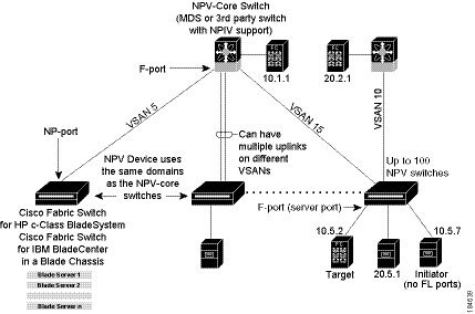
NPV addresses the increase in the number of domain IDs needed to deploy a large number of the ports by making a fabric or module switch appear as a host to the core Fibre Channel switch, and as a Fibre Channel switch to the servers in the fabric or blade switch. NPV aggregates multiple locally connected N ports into one or more external NP links, which shares the domain ID of the NPV core switch among multiple NPV switches (see Figure 20-1). NPV also allows multiple devices to attach to the same port on the NPV core switch, thereby reducing the need for more ports on the core.

Figure 20-1 Cisco NPV Fabric Configuration

While NPV is similar to N port identifier virtualization (NPIV), it does not offer exactly the same functionality. NPIV provides a means to assign multiple FC IDs to a single N port, and allows multiple applications on the N port to use different identifiers. NPIV also allows access control, zoning, and port security to be implemented at the application level. NPV makes use of NPIV to get multiple FCIDs allocated from the core switch on the NP port.

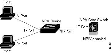
Figure 20-2 shows a more granular view of an NPV configuration at the interface level.

Figure 20-2 Cisco NPV Configuration-Interface View


Note In-order data delivery is not required in NPV mode because the exchange between two end devices always takes the same uplink to the core from the NPV device. For traffic beyond the NPV device, core switches will enforce in-order delivery if needed and/or configured.


NP Ports

An NP port (proxy N port) is a port on a device that is in NPV mode and connected to the NPV core switch using an F port. NP ports behave like N ports except that in addition to providing N port behavior, they also function as proxies for multiple, physical N ports.

NP Links

An NP link is basically an NPIV uplink to a specific end device. NP links are established when the uplink to the NPV core switch comes up; the links are terminated when the uplink goes down. Once the uplink is established, the NPV switch performs an internal FLOGI to the NPV core switch, and then (if the FLOGI is successful) registers itself with the NPV core switch's name server. Subsequent FLOGIs from end devices in this NP link are converted to FDISCs. For more details refer to the "Internal FLOGI Parameters" section.

Server links are uniformly distributed across the NP links. All the end devices behind a server link will be mapped to only one NP link.

Internal FLOGI Parameters

When an NP port comes up, the NPV device first logs itself in to the NPV core switch and sends a FLOGI request that includes the following parameters:

The fWWN (fabric port WWN) of the NP port used as the pWWN in the internal login.

The VSAN-based sWWN (switch WWN) of the NPV device used as nWWN (node WWN) in the internal FLOGI.

After completing its FLOGI request, the NPV device registers itself with the fabric name server using the following additional parameters:

Switch name and interface name (for example, fc1/4) of the NP port is embedded in the symbolic port name in the name server registration of the NPV device itself.

The IP address of the NPV device is registered as the IP address in the name server registration of the NPV device.


Note The BB_SCN of internal FLOGIs on NP ports is always set to zero. The BB_SCN is supported at the F-port of the NPV device.


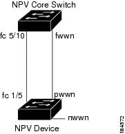
Figure 20-3 shows the internal FLOGI flows between an NPV core switch and an NPV device.

Figure 20-3 Internal FLOGI Flows

Table 20-1 identifies the internal FLOGI parameters that appear in Figure 20-3.

Table 20-1 Internal FLOGI parameters  

Parameter
Derived From

pWWN

The fWWN of the NP port.

nWWN

The VSAN-based sWWN of the NPV device.

fWWN

The fWWN of the F port on the NPV core switch.

symbolic port name

The switch name and NP port interface string.

Note If there is no switch name available, then the output will simply read "switch." For example, switch: fc1/5.

IP address

The IP address of the NPV device.

symbolic node name

The NPV switch name.


Although fWWN-based zoning is supported for NPV devices, it is not recommended because:

Zoning is not enforced at the NPV device (rather, it is enforced on the NPV core switch).

Multiple devices behind an NPV device log in via the same F port on the core (hence, they use same fWWN and cannot be separated into different zones).

The same device might log in using different fWWNs on the core switch (depending on the NPV link it uses) and may need to be zoned using different fWWNs.

Default Port Numbers

Port numbers on NPV-enabled switches will vary depending on the switch model. For details about port numbers for NPV-eligible switches, see Chapter 11, "On-Demand Port Activation Licensing."

NPV Guidelines and Requirements

Following are recommended guidelines and requirements when deploying NPV:

NPV core switches must support NPIV.

You can have up to 100 NPV devices.

Nondisruptive upgrades are supported. See Chapter 14, "Software Images."

Port tracking is supported. See Chapter 65, "Configuring Port Tracking."

You can configure zoning for end devices that are connected to NPV devices using all available member types on the NPV core switch. If fWWN, sWWN, domain, or port-based zoning is used, then fWWN, sWWN or the domain/port of the NPV core switch should be used.

Port security is supported on the NPV core switch for devices logged in via NPV.

NPV uses a load balancing algorithm to automatically assign end devices in a VSAN to one of the NPV core switch links (in the same VSAN) upon initial login. If there are multiple NPV core switch links in the same VSAN, then you cannot assign a specific one to an end device.

Both servers and targets can be connected to an NPV device.

Remote SPAN is not supported.

Local switching is not supported; all traffic is switched using the NPV core switch.

NPV devices can connect to multiple NPV core switches. In other words, different NP ports can be connected to different NPV core switches.

NPV supports NPIV-capable module servers (nested NPIV).

Only F, NP, and SD ports are supported in NPV mode.

Configuring NPV

When you enable NPV, your system configuration is erased and the system is rebooted with NPV mode enabled.

Multiple VSAN Support

By grouping devices into different NPV sessions based on VSANs, it is possible to support multiple VSANs at the NPV-enabled switch. The correct uplink must be selected based on the VSAN(s) that the uplink can carry.

Configuring NPV with Fabric Manager

To use Fabric Manager and Device Manager to configure NPV, follow these steps:


Step 1 Launch Device Manager from the core NPV switch to enable NPIV on the core NPV switch. From the Admin drop-down menu, select Feature Control. Select enable for the NPIV feature (see Figure 20-4)

Figure 20-4 Enabling NPIV and NPV

Step 2 Click Apply.

Step 3 From the Interface drop-down menu, select FC All to configure the NPIV core switch port as an F Port.

Step 4 In the Mode Admin column, select the F port mode and click Apply.

Step 5 Launch Device Manager from the NPV device to enable NPV on the NPV device. From the Admin drop-down menu, select Feature Control. Select enable for the NPV feature and click Apply.

Step 6 From the Interface drop-down menu, select FC All to configure the external interfaces on the NPV device.

Step 7 In the Mode Admin column, select the NP port mode and click Apply.

Step 8 To configure the server interfaces on the NPV device, from the Interface drop-down menu, select FC All.

Step 9 In the Mode Admin column, select F port mode and click Apply.

Step 10 The default Admin status is down. After configuring port modes, you must select up Admin Status to bring up the links.


Note On the 91x4 platform, before you upgrade to 3.2(2c) or downgrade from 3.2(2c), shut the F-ports connected to NPIV capable hosts, and then disable the NPIV feature. After the upgrade or downgrade is complete, enable the NPIV feature and up the F-ports.


Note On the 91x4 platform, before you downgrade from 3.2(2c) to prior versions, shut the F-port, enable and disable the FC domain persistency for that VSAN and then up the F-port.


DPVM Configuration

When NPV is enabled, the following requirements must be met before you configure DPVM on the NPV core switch:

You must explicitly configure the WWN of the internal FLOGI in DPVM.

If DPVM is configured on the NPV core switch for an end device that is connected to the NPV device, then that end device must be configured to be in the same VSAN. Logins from a device connected to an NPV device will fail if the device is configured to be in a different VSAN. To avoid VSAN mismatches, ensure that the internal FLOGI VSAN matches the port VSAN of the NP port.

The first login from an NP port determines the VSAN of that port. If DPVM is configured for this first login-which is the internal login of the NPV device-then the NPV core switch's VSAN F port is located in that VSAN. Otherwise, the port VSAN remains unchanged.

For details about DPVM configuration, see Chapter 27, "Creating Dynamic VSANs."

NPV and Port Security

Port security is enabled on the NPV core switch on a per interface basis. To enable port security on the NPV core switch for devices logging in via NPV, you must adhere to the following requirements:

The internal FLOGI must be in the port security database; in this way, the port on the NPV core switch will allow communications/links.

All the end device pWWNs must also be in the port security database.

Once these requirements are met, you can enable port security as you would in any other context. For details about enabling port security, see Chapter 44, "Configuring Port Security."