Installation and Configuration Note for the Catalyst 4500 Series Supervisor Engine IV
Available Languages
Table Of Contents
Installation and Configuration Note for the Catalyst 4000 Family Supervisor Engine IV
Features of the Supervisor Engine Front Panel
Installing and Removing the Supervisor Engine
Installing the Supervisor Engine
Removing the Supervisor Engine
Attaching Module Interface Cables
Configuring Your Supervisor Engine
GBIC Handling Guidelines and Installation
Standards Compliance Specifications
Obtaining Documentation and Submitting a Service Request
Installation and Configuration Note for the Catalyst 4000 Family Supervisor Engine IV
Product Numbers: WS-X4515 = Catalyst 4000 Family Supervisor Engine IV
This publication describes how to install and verify the operation of the Catalyst 4000 family Supervisor Engine IV. Refer to the software configuration guide for your switch for configuration information for the supervisor engines and switching modules.
Contents
This document contains these sections:
•
Installing and Removing the Supervisor Engine
•
Attaching Module Interface Cables
•
Configuring Your Supervisor Engine
•
GBIC Handling Guidelines and Installation
•
Standards Compliance Specifications
•
Obtaining Documentation and Submitting a Service Request
Safety Overview
Throughout this publication, safety warnings appear in procedures that may harm you if performed incorrectly. A warning symbol precedes each warning statement.
Supervisor Engine IV
This section describes the Catalyst 4000 family Supervisor Engine IV (WS-X4515). This supervisor engine provides data path and data control for all network interfaces.
The Supervisor Engine IV is supported by the Catalyst 4006, 4503, 4506, and 4507R switches. Install the Supervisor Engine IV in slot 1 of all Catalyst 4000 family switches. You can install two Supervisor Engine IVs in a Catalyst 4507R switch with the second supervisor engine serving as a redundant supervisor engine. The Supervisor Engine IV in slot 1 of the Catalyst 4507R switch is the primary supervisor engine. The Supervisor Engine IV in slot 2 of the Catalyst 4507R switch is the redundant supervisor engine.
The supervisor engine is hot swappable, but packets are not forwarded when the supervisor engine has been removed. When a supervisor engine is reinserted, the system reboots.
Figure 1 Catalyst 4000 Family Supervisor Engine IV (WS-X4515)
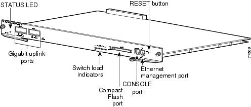
The supervisor engine includes interfaces for SNMP, console, and Telnet, and provides management functions, such as environmental status monitoring.
Features of the Supervisor Engine Front Panel
The following sections describe the LEDs, connectors, and switches on the Catalyst 4000 family Supervisor Engine IV:
•
LEDs
•
Gigabit Ethernet Uplink Ports
LEDs
Table 1 describes the LEDs on the supervisor engine front panel.
Table 1 Supervisor Engine LEDs (WS-X4515)
STATUS
Indicates the results of a series of self-tests.
Green
All diagnostic tests passed.
Red
A test failed.
Orange
System boot or diagnostic test is in progress.
Off
Module is disabled.
UTILIZATION
Green 1-100%
If the switch is operational, this display indicates the current traffic load over the backplane (as an approximate percentage).
Link
Indicates the status of the 10/100BASE-T Ethernet management port or uplink ports.
Green
The link is operational.
Orange
The link is disabled by user.
Flashing orange
The power-on self-test indicates a faulty port.
Off
No signal is detected or there is a link configuration failure.
Active
Indicates whether the uplink port is active.
Green
The port is active.
Off
The port is not active.
ACTIVE
The LED to the right of the uplink ports is only used in switches with two supervisors to identify the active supervisor.
Gigabit Ethernet Uplink Ports
The Gigabit Ethernet uplink ports operate in full-duplex mode only. These ports use the 1000BASE-SX, 1000BASE-LX/LH, and 1000BASE-ZX Gigabit Interface Converters (GBICs). GBICs have SC connectors to interface with multimode fiber (MMF) and single-mode fiber (SMF) cable. For further information on GBICs, see the "GBIC Handling Guidelines and Installation" section.
Ethernet Management Port
The Ethernet management port can be used (in ROMMON mode only) to recover a switch software image that has been corrupted or destroyed due to a network catastrophe. When using Cisco IOS Release 12.2(50)SG or later, this port can also perform the same functions as the console port. For earlier Cisco IOS software releases, this port is not active while the switch is operating normally.
Console Port
The Catalyst 4000 family Supervisor Engine IV console port has an EIA/TIA-232 RJ-45 connector. The console port allows you to perform the following functions:
•
Configure the switch from the CLI
•
Monitor network statistics and errors
•
Configure SNMP agent parameters

Note
EIA/TIA-232 was known as recommended standard RS-232 before its acceptance as a standard by the Electronic Industries Alliance (EIA) and Telecommunications Industry Association (TIA).
Reset Button
The Reset button is used to restart the switch.

Note
Use a paper clip or other small, pointed object to press the Reset button.
Flash Port
The Flash port accepts a Type 1 compact Flash card. You can use it for file transfer tasks such as loading a new software image. The Flash card (MEM-C4K-FLD64M= or MEM-C4K-FLD128M=) is optional.
For more information, refer to Using the Compact Flash on the Catalyst 4000 Family Supervisor Engine III and IV at the following URL:
http://www.cisco.com/en/US/docs/switches/lan/catalyst4500/hardware/configuration/notes/OL_2788.html
Port Cabling Specifications
This section provides port cabling specifications and includes the following subsections:
The length of your networks and the distances between connections depend on the type of signal, the signal speed, and the transmission medium (the type of cabling used to transmit the signals). The distance and rate limits in this document are the IEEE-recommended maximum speeds and distances for signaling. Table 2 shows the transmission speed versus the distance.
Table 2 EIA/TIA-232 Transmission Speed in Contrast with Distance
2400
200
60
4800
100
30
9600
50
15
19,200
25
7.6
38,400
12
3.7
56,000
8.6
2.6
Maximum Cable Distances
Table 3 shows the maximum cable distances for transceiver speed and cable type.
Table 3 Maximum Cable Distances
10 Mbps
Category 3 UTP
Half or full
328 ft (100 m)
10 Mbps
MMF
Half or full
1.2 mi (2 km)
100 Mbps
Category 5 UTP
Half or full
328 ft (100 m)
100 Mbps
MMF
Half
1312 ft (400 m)
100 Mbps
MMF
Full
1.2 mi (2 km)
Table 4 provides cabling specifications for the GBICs that you install in the Gigabit Ethernet port modules. All GBIC ports have SC-type connectors, and the minimum cable distance for all GBICs listed is 6.5 feet (2 meters).
Table 4 GBIC Port Cabling Specifications
(MHz/km)SX1
850
MMF
62.5
160
722 ft (220 m)
62.5
200
902 ft (275 m)
50.0
400
1640 ft (500 m)
50.0
500
1804 ft (550 m)
LX/LH
1300
MMF2
62.5
500
1804 ft (550 m)
50.0
400
1804 ft (550 m)
50.0
500
1804 ft (550 m)
SMF
9/10
-
6.2 mi (10 km)
ZX
1550
SMF
9/10
-
43.5 mi (70 km)
SMF3
9/10
62.1 mi (100 km)
1 MMF only.
2 Patch cord required (see the "Using a Patch Cord" section for details).
3 Dispersion-shifted single-mode fiber-optic.
Using a Patch Cord
When using the LX/LH GBIC with 62.5-micron diameter MMF, you must install a mode-conditioning patch cord (Cisco product number CAB-GELX-625 or equivalent) between the GBIC and the MMF cable on both the transmit and receive ends of the link.
The patch cord is required for link distances greater than 984 feet (300 meters) and must comply with IEEE standards. The IEEE found that link distances could not be met with certain types of fiber-optic cable due to a problem in the center of some fiber-optic cable cores. The solution is to launch light from the laser at a precise offset from the center by using the patch cord. At the output of the patch cord, the LX/LH GBIC is compliant with the IEEE 802.3z standard for 1000BASE-LX. For a detailed description of this problem, refer to the installation guide for your switch.

Note
We do not recommend using the LX/LH GBIC with MMF without a patch cord for very short link distances (tens of meters) either. The result could be an elevated bit error rate (BER).
Cisco Gigabit Ethernet products have been tested and evaluated to comply with the standards listed in Appendix A, "Specifications," of the installation guide for your switch. All equivalent cables should also meet these standards.
Installing and Removing the Supervisor Engine
All Catalyst 4000 family switches support hot swapping, which lets you install, remove, replace, and rearrange supervisor engines and switching modules without powering the system off. When the system detects that a switching module has been installed or removed, it runs diagnostic and discovery routines automatically, acknowledges the presence or absence of the module, and resumes system operation with no operator intervention.
This section contains the following subsections:
•
Installing the Supervisor Engine
•
Removing the Supervisor Engine
Required Tools
You will need these tools to install a supervisor engine in a Catalyst 4000 family switch:
•
Number 1 and number 2 Phillips screwdrivers for the captive installation screws on most modules
•
3/16-inch flat-blade screwdriver for the captive installation screws on other modules
•
Antistatic mat or antistatic foam
•
Wrist strap or other grounding device

Note
Whenever you handle supervisor engines, use a wrist strap or other grounding device to prevent ESD damage.
Installing the Supervisor Engine
Catalyst 4000 family switches have horizontal chassis slots that are numbered from top to bottom. On the Catalyst 4006, 4503, and 4506 switches, you can only install the supervisor engine in slot 1. On the Catalyst 4507R switch, you install the primary supervisor engine in slot 1. You can install an optional redundant supervisor engine in slot 2.
WarningDuring this procedure, wear grounding wrist straps to avoid ESD damage to the card. Do not directly touch the backplane with your hand or any metal tool, or you could shock yourself.

CautionTo prevent ESD damage, handle supervisor engines by the carrier edges only.
To install a supervisor engine in a Catalyst 4000 family switch, follow this procedure:
Step 1
Take the necessary precautions to prevent ESD damage as described in the Site Preparation and Safety Guide.
Step 2
Ensure that you have enough clearance to accommodate any interface equipment that you will connect directly to the supervisor engine ports.
Step 3
Loosen the captive installation screws that secure the switching-module filler plate or the existing supervisor engine (whichever is present) and remove it.
Step 4
Remove the supervisor engine filler plate or the existing supervisor engine from slot 1. If a switching module filler plate was installed, save it for future use. If you are removing an existing supervisor engine, see the "Removing the Supervisor Engine" section.
Step 5
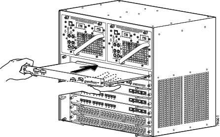
To install the new supervisor engine, grasp the switching module front panel with one hand and place your other hand under the carrier to support the supervisor engine, as shown in Figure 2. Do not touch the printed circuit boards or connector pins.
Step 6
Align the edges of the supervisor engine carrier with the slot guides on the sides of the switch chassis, as shown in Figure 2.
Figure 2 Installing the Supervisor Engine in the Chassis
Step 7
Pivot the two module ejector levers out and away from the faceplate.
Step 8
Carefully slide the supervisor engine into the slot until the notches on both ejector levers engage the chassis sides.
Step 9
Using the thumb and forefinger of each hand, simultaneously pivot in both ejector levers to fully seat the supervisor engine in the backplane connector.

CautionAlways use the ejector levers when installing or removing a supervisor engine. A supervisor engine that is partially seated in the backplane will not function correctly.
Step 10
Use a screwdriver to tighten the captive installation screws on each end of the supervisor engine faceplate.
To check the status of the module, perform these steps:
Step 1
Ensure that the LED labeled Status is green (module operational).
Step 2
When the switch is online, enter the show module command. Verify that the system acknowledges the new module and that the module's status is good.
Step 3
If the module is not operational, reseat it. If the module is still not operational, contact your customer service representative.
Removing the Supervisor Engine
WarningBecause invisible radiation may be emitted from the aperture of the port when no fiber cable is connected, avoid exposure to radiation and do not stare into open apertures.
WarningDuring this procedure, wear grounding wrist straps to avoid ESD damage to the card. Do not directly touch the backplane with your hand or any metal tool, or you could shock yourself.

CautionTo prevent ESD damage, handle supervisor engines by the carrier edges only.
To remove a supervisor engine from a Catalyst 4000 family switch, follow this procedure:
Step 1
Disconnect any network interface cables attached to the ports on the supervisor engine that you intend to remove.
Step 2
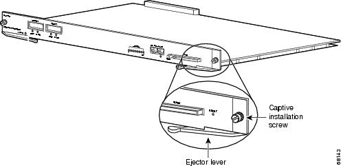
Loosen the captive installation screws (see Figure 3).
Figure 3 Captive Installation Screws and Ejector Levers
Step 3
Grasp the left and right ejector levers and simultaneously pivot the levers outward to release the supervisor engine from the backplane connector. Figure 3 shows a close-up of the right ejector lever.
Step 4
Grasp the front panel of the supervisor engine with one hand and place your other hand under the carrier to support and guide it out of the slot. Do not touch the printed circuit boards or connector pins.
Step 5
Carefully pull the supervisor engine straight out of the slot, keeping your other hand under the carrier to guide it.
Step 6
Place the supervisor engine on an antistatic mat or antistatic foam, or immediately install it in another slot.
WarningBlank faceplates and cover panels serve three important functions: they prevent exposure to hazardous voltages and currents inside the chassis; they contain electromagnetic interference (EMI) that might disrupt other equipment; and they direct the flow of cooling air through the chassis. Do not operate the system unless all cards, faceplates, front covers, and rear covers are in place.
Step 7
If the slot is to remain empty, install a switching-module filler plate (part number 800-00292-01).
Attaching Module Interface Cables
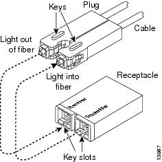
Figure 4 and Figure 5 show the connector types used to attach interface cables to the supervisor engine.
Figure 4 RJ-45 Connector


Note
Always keep caps and plugs on the fiber-optic connectors on the cable and the switch when they are not in use.
WarningBecause invisible radiation may be emitted from the aperture of the port when no fiber cable is connected, avoid exposure to radiation and do not stare into open apertures.
Figure 5 SC-Type Fiber-Optic Connector
Configuring Your Supervisor Engine
For information and commands to configure your supervisor engine, refer to the Software Configuration Guide for your switch.
GBIC Handling Guidelines and Installation
A GBIC (see Figure 6) is a hot swappable input/output device that plugs into the Gigabit Ethernet port of a supervisor engine and links the supervisor engine with a fiber-optic network. GBICs are online swappable.
Figure 6 Gigabit Interface Converter
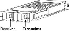
The following GBIC media types are supported:
•
1000BASE-SX (WS-G5484)
•
1000BASE-LX/LH (WS-G5486)
•
1000BASE-ZX (WS-G5487)

CautionBecause of interoperability issues, Cisco does not support GBICs purchased from third-party vendors.
Cisco 1000BASE-LX/LH interfaces fully comply with the IEEE 802.3z 1000BASE-LX standard. However, their higher optical quality allows them to reach 10 km over SMF cable instead of the 5 km specified in the standard.
If an LX/LH GBIC designed for operation on an SMF cable is directly coupled to an MMF cable, an effect known as Differential Mode Delay (DMD) might occur. See the Catalyst 4000 Family Module Installation Guide for more information.
This section describes the following topics:
Installing a GBIC
A supervisor engine can be shipped with or without GBICs installed.

CautionWhen removing or inserting a GBIC, always wear an ESD wrist strap connected to the ESD wrist strap connector.

CautionUnnecessary removal or insertion of a GBIC can lead to premature failure of the GBIC. A GBIC has a lifetime of 100 to 500 removals and insertions.

Note
This product has been evaluated to and complies with acceptable-safety-emission limits for Class 1 lasers. However, you should still take general precautions when working with lasers.
WarningBecause invisible radiation may be emitted from the aperture of the port when no fiber cable is connected, avoid exposure to radiation and do not stare into open apertures.
To install a GBIC, follow this procedure:
Step 1
Remove the GBIC from its protective packaging.
Step 2
Verify that the GBIC is the correct type for your network by checking the GBIC part number. The part number indicates whether it is 1000BASE-SX, 1000BASE-LX/LH, or 1000BASE-ZX.
Step 3
Grasp the sides of the GBIC with your thumb and forefinger; insert the GBIC into the desired slot on the front of the module (see Figure 7).

Note
GBICs are keyed to prevent incorrect insertion into a slot.
Figure 7 Installing a GBIC

Step 4
Slide the GBIC into the slot until you hear a click. The click indicates that the GBIC is locked into the slot.
Step 5
When you are ready to attach the fiber-optic cable, remove the plug from the GBIC and save it for future use.

CautionDo not remove the plugs from the GBIC optical bores or the fiber-optic cable until you are ready to connect the cable. The plugs protect the GBIC optical bores and cable from contamination.
Step 6
Remove the plugs from the SC-type connector on the fiber-optic cable (see Figure 5 on page 13). Insert the connector into the GBIC.

Note
When you plug the SC-type connector into the GBIC, ensure that you fully insert the Tx and Rx fiber-optic cables into the SC-type connector.

Note
If you are using the LX/LH GBIC with MMF, you need to install a patch cord between the GBIC and the MMF cable. See the "Using a Patch Cord" section for details.
Removing a GBIC
WarningBecause invisible radiation may be emitted from the aperture of the port when no fiber cable is connected, avoid exposure to radiation and do not stare into open apertures.
To remove a GBIC, follow this procedure:
Step 1
Disconnect the fiber-optic cable from the GBIC SC-type connector.
Step 2
Release the GBIC from the slot by simultaneously squeezing the plastic tabs (one on each side of the GBIC).
Step 3
Slide the GBIC out of the slot.
Step 4
Install the two plugs into the GBIC optical bores, and place the GBIC in its protective packaging.
GBIC Maintenance Guidelines
To properly maintain GBICs, follow these guidelines:
•
GBICs are sensitive to static. To prevent ESD damage, follow normal handling procedures.
•
GBICs are sensitive to dust. When the GBIC is stored or when a fiber-optic cable is not plugged in, always keep plugs in the optical bores.
•
The most common source of contaminants in the optical bores is debris picked up on the ferrules of the optical connectors. Use an alcohol swab or Kim-Wipe to clean the ferrules of the optical connector.
Standards Compliance Specifications
When installed in a system, the Catalyst 4000 family modules comply with the standards listed in Table 5:
Table 5 Standards Compliance Specifications
CE1 Marking
UL2 60950, CSA3 -C22.2 No. 60950, EN4 60950, IEC5 60950, TS0016 ,
AS/NZS7 3260FCC9 Part 15, Class A (CFR10 47) (USA), ICES11 -003 Class A (Canada), EN 55022 Class A (Europe), CISPR2212 Class A (International), AS/NZS 3548 Class A (Australia), and VCCI13 Class A (Japan) with UTP14
1 CE = European Compliance
2 UL = Underwriters Laboratory
3 CSA = Canadian Standards Association
4 EN = European Norm
5 IEC = International Electrotechnical Commission
6 TS = technical specifications
7 AS/NZS = Australia Standards/New Zealand Standards
8 EMC = electromagnetic compatibility
9 FCC = U.S. Federal Communications Commission
10 CFR = Code of Federal Regulations
11 ICES = Interference-Causing Equipment Standard
12 CISPR = Comite International Special des Perturbation Radioelectriques
13 VCCI = Voluntary Control Council for Information Technology Equipment
14 UTP = unshielded twisted-pair
The following modules have been found to comply with the limits for a Class A digital device per FCC (CFR 47) Part 15, ICES 003, EN55022, CISPR22, AS/NZS 3548, and VCCI with UTP cables, and complies with the limits for a Class B digital device per EN55022, CISPR22, AS/NZS 3548, and VCCI with shielded FTP cables with the following modules:
WS-X4012
WS-X4148-RJ21
WS-X4412-2GB-T
WS-X4013
WS-X4148-RJ45V
WS-X4418-GB
WS-X4014
WS-X4232-GB-RJ
WS-X4424-GB-RJ45
WS-X4019
WS-X4232-L3
WS-X4448-GB-LX
WS-X4124-FX-MT
WS-X4232-RJ-XX
WS-X4604-GWY
WS-X4148-FX-MT
WS-U4504-FX-MT
WS-X4148-RJ
WS-X4306-GB
Related Documentation
For more detailed installation and configuration information, refer to the following:
•
Catalyst 4000 Series Installation Guide
•
Catalyst 4500 Series Installation Guide
•
Catalyst 4000 Series Module Installation Guide
•
Regulatory Compliance and Safety Information for the Catalyst 4500 Series Switches
•
Software Configuration Guide—Catalyst 4000 Family, Catalyst 2948G, and Catalyst 2980G Switches
•
Command Reference—Catalyst 4000 Family, Catalyst 2948G, and Catalyst 2980G Switches
•
System Message Guide—Catalyst 6000 Family, Catalyst 5000 Family, Catalyst 4000 Family, Catalyst 2926G Series, Catalyst 2948G, and Catalyst 2980G Switches
Obtaining Documentation and Submitting a Service Request
For information on obtaining documentation, submitting a service request, and gathering additional information, see the monthly What's New in Cisco Product Documentation, which also lists all new and revised Cisco technical documentation, at:
http://www.cisco.com/en/US/docs/general/whatsnew/whatsnew.html
Subscribe to the What's New in Cisco Product Documentation as a Really Simple Syndication (RSS) feed and set content to be delivered directly to your desktop using a reader application. The RSS feeds are a free service and Cisco currently supports RSS version 2.0.

Contact Cisco
- Open a Support Case

- (Requires a Cisco Service Contract)

 Feedback