Feedback
Contents
- MediaSense Features and Services
- Network services
- Feature services
- Search and Play
- Search for, play, or download a recorded call
- Architecture
- Unified Communications Manager deployments
- Cisco Unified Border Element deployments
- Unified CM and CUBE scenario differences
- Supported deployments
- MediaSense cluster deployments
- Single-server deployments
- Dual-server deployments
- Three-server deployments
- Four-server and five-server deployments
- MediaSense high availability deployments
- Data replication considerations
- Data replication and recovery for primary or secondary node
- Deployment considerations for high availability
- Failure condition considerations
- MediaSense requirements
- Media storage requirements
- Hardware requirements
- Software requirements
- License requirements
- Other requirements
- Port usage
MediaSense Features and Services
MediaSense is the media-capture platform for Cisco Unified Communications. It can be used to record calls in Cisco and non-Cisco contact centers; however, non-Cisco contact centers must use the Cisco Unified Border Element (CUBE) as the ingress point.
MediaSense can be used by compliance recording companies whose regulatory environment requires all sessions to be recorded and maintained. These recordings can later be used by a compliance auditor or a contact center supervisor to resolve customer issues or for training purposes. The recordings can also be used by speech analytics servers or transcription engines.
MediaSense uses Unified Communications Manager (Unified CM) to provide user-authentication services. It uses Web 2.0 application programming interfaces (APIs) to expose its functionality to third-party customers to enable them to create custom applications. The product is supported on Microsoft Windows 7 and the Apple Mac OS.
- Network services
- Feature services
- Search and Play
- Architecture
- Unified Communications Manager deployments
- Cisco Unified Border Element deployments
- Supported deployments
- MediaSense cluster deployments
- MediaSense high availability deployments
- MediaSense requirements
- Port usage
Network services
Network services include the following:
- Cisco MediaSense Administration: Enables you to configure MediaSense using a graphical user interface.
- Cisco MediaSense Serviceability Administration: Enables you to configure the MediaSense Serviceability application using a graphical user interface.
- System Service: Enables you to control service operations within the MediaSense clusters. This service manages the clustering and setup functionality for the secondary server and expansion servers.
- Perfmon Agent: Enables you to control the performance monitoring infrastructure within the MediaSense Serviceability Administration interface. The Java Management Extensions (JMX) technology, which allows you to manage and monitor applications and other system objects, is represented by objects called Managed Beans (MBeans). The Perfmon Agent retrieves the counter values from the JMX MBeans and writes them to the Unified CM database.
- Diagnostics Service: Enables you to troubleshoot and debug MediaSense. This service is available in all MediaSense servers.
In the MediaSense and Unified OS user interfaces, each MediaSense service name is preceded by the product name. To avoid redundancy in this document, service names are sometimes referred to without the preceding product name.
Network services are started automatically after installation in each server in the cluster. If advised to do so by Cisco support personnel, network services can be stopped.
Feature services
MediaSense contains the following feature services:
- Configuration service: saves and updates all changes made to the MediaSense configuration database. Each multiple-server cluster can have only two instances of the configuration service, one instance is in the primary server and the other instance is in the secondary server. If a cluster has more than two servers, the expansion servers cannot have a configuration service.
- API service: processes API requests and enables communication between the user interface and the server. You can enable the API service only after the database service is enabled. Each multiple-server cluster can have only two instances of the API service, one instance is in the primary server and the other instance is in the secondary server. If a cluster has more than two servers, the expansion servers do not have an API service.
- Database service: contains and controls the meta database and the configuration database. Each multiple-server cluster can only have two instances of the database service, one instance is in the primary server and the other instance is in the secondary server. Each server writes data only to its local database. The primary and secondary servers interact to synchronize data.
- Storage management agent (SM agent): monitors the overall storage in each server in the cluster and generates threshold events based on disk usage. This service is available in all servers and should be activated before the media service and call control service.
- Media service: receives, saves, and plays back media. The media service must be enabled before the call control service. This service is available in all servers in the cluster.
- Call control service: coordinates call receiving and recording. The call control service can only be enabled if the media service is already enabled. This service is available in all servers in the cluster. The call control service is referred to as a SIP trunk in the Unified CM user interface and Unified CM documentation.
All feature services are installed on the primary and secondary nodes (servers) in a cluster. Expansion nodes have only the media service, call control service, and SM agent.
Search and Play
After MediaSense is installed and configured, use the Search and Play application to search for specific media files, play them, or download them to your desktop.
Access the Search and Play application from
Note
Before launching Search and Play, you'll need to install the 32-bit version of JDK on Windows OSs and the 64-bit version on Macs. Also, ensure that you have JDK7 update 25 or later installed.
The MediaSense media player is implemented as a downloadable Java application. Due to recent security enhancements in Java, users are asked to accept a pop-up security warning every time the Java application is executed; meaning that users must accept a security warning every time a recording is played.
Since the application does not run as part of the browser executable, it is subject to the security requirements of the Java Virtual Machine (JVM) that is installed on the user's computer (rather than those of the browser). A troubleshooting tip provides instructions for setting up each client desktop where Search and Play is executed to avoid the warning (http://docwiki.cisco.com/wiki/Administration:_Search_and_Play_application_users_encounter_security_warning_before_each_playback#Search_and_Play_application_users_encounter_security_warning_before_each_playback).
Note
The media player takes longer to start in IE9 than in Firefox. IE9 users may also see an option to open a downloaded jnlp file.When prompted for login credentials, use the API user credentials defined on the MediaSense API User Configuration page of the Administration application.
Search for, play, or download a recorded call
Procedure
Architecture
MediaSense is part of the solution for Unified Communications and runs on Cisco Unified Operating System (Unified OS), Release 9.0.
MediaSense architecture contains the following components:
- Application layer:
- The Search and Play application allows you to play back recordings.
- APIs support real-time recording controls (such as hold, pause, and resume) for third-party applications.
- Application and media APIs incorporate requirements from various industry partners and are published for use by third-party applications.
- The API Service provides web service interfaces to enable applications to search for and retrieve recordings and associated session history and metadata. This metadata information is stored in the Meta database.
- Media processing layer:
- Network layer:
Unified Communications Manager deployments
Unified Communications Manager (Unified CM) must be configured appropriately to direct recordings to MediaSense recording servers. This includes configuring a recording profile, various SIP parameters, and, because MediaSense uses the Administrative XML layer (AXL) to authenticate users, the Unified CM AXL service must be enabled on at least one of its servers.
A basic Unified CM deployment for MediaSense requires one of the phones to be configured for recording. If both phones are configured for recording, two separate recording sessions are captured. Media forked by a phone is sent to the recording device where the forked streams are captured. See the Cisco MediaSense Solution Reference Network Design at http://www.cisco.com/en/US/products/ps11389/products_implementation_design_guides_list.html for further details.
All Cisco IP Phones that MediaSense supports have a built-in bridge (BIB) that allows incoming and outgoing media streams to be forked. MediaSense makes use of this capability to record inbound and outbound forked media. For more details about media forking, see the Unified CM documentation at http://www.cisco.com/en/US/products/sw/voicesw/ps556/prod_maintenance_guides_list.html.
Cisco Unified Border Element deployments
Cisco Unified Border Element (CUBE) is the Cisco session border controller (SBC) gateway that facilitates connectivity between independent VoIP networks by enabling SIP, H.323, VoIP, and video conference calls from one IP network to another.
MediaSense integrates with CUBE to enable recording without regard to the endpoint type. Because of this capability, MediaSense can use CUBE to record inbound and outbound media.
See the CUBE documentation for more information about CUBE.
- Generic CUBE configuration details are found at http://www.cisco.com/en/US/docs/ios/ios_xe/voice_cube_-_ent/configuration/guide/cube_ent/vb_book_xe.html.
- Specific recording configuration details are found at http://www.cisco.com/en/US/docs/ios-xml/ios/voice/cube_proto/configuration/15-2mt/cube-network-based.html.
The following figure illustrates a MediaSense deployment with CUBE. Even in a CUBE deployment, MediaSense depends on Unified CM to provide authentication services.
In the preceding illustration, the real time protocol (RTP) carries voice data between the endpoints and CUBE. The session initiation protocol (SIP) carries call signaling information between the endpoints and CUBE. Two RTP unidirectional streams represent two audio streams forked from CUBE to MediaSense. Streams from CUBE to MediaSense are unidirectional because only CUBE sends data to MediaSense; MediaSense does not send any media to CUBE. CUBE has three dial-peers: inbound, outbound, and forking. (See Dial-peer level setup for more information.)
Typically, CUBE can fork only SIP-to-SIP calls. However, because you can use the same Cisco router as both a TDM-to-IP gateway and a media-forking device for call recording, you can also record incoming TDM or analog calls—if you have the required licensing and an appropriate IOS version. (For more information, see the CUBE documentation at http://www.cisco.com/go/cube.)
To use this feature, you must enable both gateway and border-element functionality in the device. You can configure the gateway to receive the TDM or analog call and then to feed the call back to itself as a SIP call with a different dialed number. When you configure this loop, the router actually handles each call twice. (This cuts the router capacity in half and CUBE can process only half as many calls.) For more information, see the Media forking on a TDM gateway section in the Cisco MediaSense Developer Guide at http://www.cisco.com/en/US/products/ps11389/products_programming_reference_guides_list.html and the MediaSense FAQ article at http://docwiki.cisco.com/wiki/FAQs_for_Cisco_MediaSense#How_to_Configure_a_TDM_Gateway_for_Media_Forking.
Unified CM and CUBE scenario differences
Unified CM is used to set up the recording profile and call control service connection (SIP trunk) with MediaSense. Similarly, with CUBE, the dial-peers and media class settings determine communication with MediaSense.
Note
See the Cisco MediaSense Solution Reference Network Design at http://www.cisco.com/en/US/products/ps11389/products_implementation_design_guides_list.html for further details about CUBE media forking and UC endpoints media forking.Almost everything that is not related to call signaling is the same between Unified CM scenarios and CUBE scenarios using MediaSense.
Regardless of whether MediaSense is deployed with Unified CM or CUBE; events, response codes, and parameter definitions are the same for both scenarios. All events, response codes, and parameters are explained in detail in the Cisco MediaSense Developer Guide at http://www.cisco.com/en/US/products/ps11389/products_programming_reference_guides_list.html.
Table 1 Unified CM and CUBE scenario differencesMediaSense feature
with Unified CM
with CUBE
Initiating recordings
The direct outbound recording scenario, which is initiated when a client calls the startRecording API, is supported with Unified CM deployments.
The direct outbound recording scenario, which is initiated when a client calls the startRecording API, is not supported with CUBE deployments.
Recording
Two media streams are sent to MediaSense (called Track 0 and Track 1). Recording requires two phones with at least one phone configured for media-forking capabilities (two SIP invitations).
Recording uses SIP devices (referred to as SIP User Agent in CUBE). As long as the call is processed by CUBE as a SIP call, the endpoint can be of any type. Two media streams are sent to MediaSense. These two streams ultimately result in two tracks without any differentiation for Track 0 and Track 1.
Identifying tracks for calling versus called party
See the FAQs for MediaSense website (How do you determine which track has the calling and which has the called party?).
The numerically smaller xRefCi parameter usually refers to the track of the calling party.
Track 0 contains the media stream corresponding to the dial-peer in which the media recording profile is configured.
Recording session
See the Cisco MediaSense Developer Guide at http://www.cisco.com/en/US/products/ps11389/products_programming_reference_guides_list.html for details about recording sessions and hold/resume, pause/resume, transfer/conference commands.
If a call is placed on hold, the logical recording session is terminated. When a participant resumes the call, a new recording session is created.
The SIP Session may be updated multiple times with corresponding media track events. There is only one recording session even if the call is placed on hold and resumed multiple times.
Differences in the captured recording data
See the Cisco MediaSense Solution Reference Network Design at http://www.cisco.com/en/US/products/ps11389/products_implementation_design_guides_list.html.
To obtain information such as the original calling number, called number, and type of call; see the Call Detail Records section in the Unified Communications Manager Call Detail Records Administration Guide at http://www.cisco.com/en/US/products/sw/voicesw/ps556/prod_maintenance_guides_list.html.
CUBE can store calls in an external database known as AAA - RADIUS. Calls can be searched by Cisco-GUID, which corresponds to the CCID in the MediaSense session data.
Mid-call codec change
Does not generate mid-call codec changes.
A new session starts.
Endpoint MAC address
Captured.
Not captured.
Recording media source
The endpoints provides the forked media.
CUBE provides the forked media.
Supported deployments
MediaSense supports the following deployments:
- One-server deployment: one active server.
- Two-server deployment: two active servers providing high availability.
- Three-server deployment: two active servers providing high availability and one expansion server to provide additional recording capacity.
- Four-server deployment: two active servers providing high availability and two expansion servers to provide additional recording capacity.
- Five-server deployment: two active servers providing high availability and three expansion servers to provide additional recording capacity.
Note
UCS-E installations and all installations with less than 7 vCPUs are limited to one-server and two-server deployments.
In all the deployments, the installation and configuration of the primary server differs from the installation and configuration of the other servers in the same deployment. If you are configuring any server in a MediaSense deployment, be aware that the platform administrator configures the MediaSense application administrator username and password (in addition to the platform and security password). See Install MediaSense and Unified OS for further details.
Note
The application administrator username and password must be the same on all servers in a MediaSense deployment. You can reset the application administrator username and password using the following CLI commands:MediaSense cluster deployments
In a MediaSense deployment, a cluster contains a set of servers with each server containing a set of services. Cluster architecture provides high availability (for recording but not for playback) and failover (if the primary server fails, there is automatic failover to the secondary server).
MediaSense functions only within local area networks (LAN). Wide are networks (WAN) are not supported. All MediaSense servers and Unified CM servers must be located in the same LAN. Within a LAN, the maximum round-trip delay between any two servers must be less than 2 ms.
The primary and secondary servers in a MediaSense deployment are synchronized when administrative changes are made on either server. Database replication copies the data automatically from the primary server to the secondary server, and vice versa.
The following cluster deployment rules are enforced by the installation and configuration procedures:
- All servers in the same cluster must run the same version of MediaSense.
- A MediaSense deployment can consist of one to five MediaSense servers. Each server in a cluster must always have a call control service, media service, and an SM agent.
- UCS-E installations and all installations with less than 7 vCPUs are limited to one-server and two-server deployments.
- Single-server deployments
- Dual-server deployments
- Three-server deployments
- Four-server and five-server deployments
Single-server deployments
A single-server deployment has one MediaSense server on the Unified Communications OS platform. All network services are enabled by default.
In single-server deployments, the primary server has the following feature services:Each single-server deployment supports a maximum of 300 simultaneous sessions and a busy-hour call completion (BHCC) rate of 9000 sessions per hour (with each call having a two minute average duration). Single-service deployments enable you to add more servers later to address redundancy issues, to provide high availability, to increase storage capacity, and to increase simultaneous recording capacity.
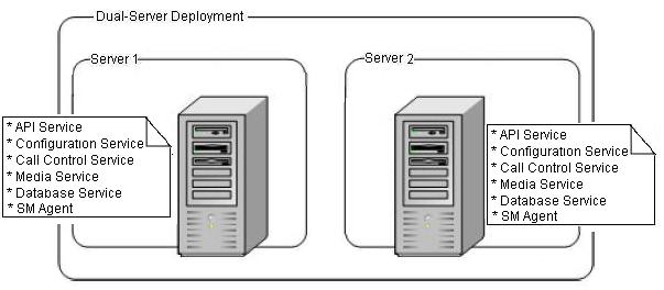
Dual-server deployments
A dual-server deployment has two MediaSense servers on the Unified Communications OS (Unified OS) platform. The first server is called the primary server. The second server is called the secondary server. All network services are enabled on both servers.
Both primary and secondary servers have the following feature services:Figure 2. Dual-server deployment. Dual-server deployments provide high availability. The recording load is automatically balanced across the primary and secondary servers because all services are always active on both servers.
Note
MediaSense does not provide automatic load balancing in the API service or the configuration service. When both of those services are enabled on the primary and secondary servers, you must point your browser or server-based API to one of these services.
See the Cisco MediaSense Solution Reference Network Design guide for details about the maximum number of simultaneous recordings, playback, and monitoring sessions that are supported.
Three-server deployments
Three-server deployments have a primary server, a secondary server, and one expansion server. All network services are enabled by default on all servers in the cluster.
The primary server and the secondary server have the following feature services:The expansion server has the following feature services:Figure 3. Three-server deployment. The three-server model provides redundancy and increases storage capacity and simultaneous recording and playback capacity. The recording load is automatically balanced across the servers because services are always active on their respective servers.
Note
MediaSense does not provide automatic load balancing in the API service and Configuration service on the primary and secondary servers. While those services are enabled, you must point your browser or server-based API to only one of these services.See the Cisco MediaSense Solution Reference Network Design Guide for details about the maximum number of simultaneous recording sessions, playback sessions, and monitoring sessions that are supported.
Four-server and five-server deployments
Four-server and five-server deployments have one primary server, one secondary server, and two or three expansion servers. All network services are enabled by default on all servers in the cluster.
Primary servers and secondary servers have the following feature services:The remaining servers, called expansion servers, only have the following feature services:Figure 4. Five-server deployment. This deployment model provides redundancy, increases storage capacity, and increases capacity for simultaneous recording and playback sessions. The recording load is automatically balanced across the servers because services are always active on their respective servers.
Note
MediaSense does not provide automatic load balancing in the API service and Configuration service on the primary and secondary servers. While those services are enabled, you must point your browser or server-based API to only one of these services.
See the Cisco MediaSense Solution Reference Network Design Guide for details about the maximum number of simultaneous recording sessions, playback sessions, and monitoring sessions that are supported.
MediaSense high availability deployments
Some deployments require that all available media is recorded. A call control service failure may result in no recordings unless your deployment supports high availability. If Unified CM cannot contact one of the MediaSense servers, you must ensure that an alternate server is available for Unified CM or CUBE to make the required connection.
For more information, see the Cisco MediaSense Solution Reference Network Design Guide at http://www.cisco.com/en/US/products/ps11389/products_implementation_design_guides_list.html.
- Data replication considerations
- Data replication and recovery for primary or secondary node
- Deployment considerations for high availability
- Failure condition considerations
Data replication considerations
Database high availability support in MediaSense deployments is provided using Informix enterprise replication (ER) for both the meta database and configuration database. While a MediaSense cluster can have up to five servers, data replication is enabled only between the primary and secondary servers.
At installation time, if the server you are installing is identified as the secondary server, the following considerations apply:
- This server automatically applies the on-tape backup from the primary server without any constraints on the data size in the primary server.
- Data replication is performed between the primary and secondary servers. So data written to the primary server is also replicated to the secondary server, and vice versa.
The replication behavior between the primary and secondary MediaSense servers differs based on the time of replication:
- Activation time: During the service activation process, Informix ER automatically begins replication between the primary and secondary servers. The differential data between both servers are replicated from the primary server to the secondary server.
- Run time: During run time, data replication is bidirectional. If, for any reason, one of the MediaSense servers is shut down or in a failed state, data continues to be written to the surviving server. When the shut down or failed server is revived, Informix ER automatically restarts between the two servers and synchronizes the data. Depending on the data size, synchronization time may vary. Retention period refers to the number of days that data can be stored on the surviving server without breaking the replication. See the Cisco MediaSense Solution Reference Network Design Guide for details about database retention period recommendations.
Data replication and recovery for primary or secondary node
If either the primary or secondary server goes out of service, the database replication process proceeds as follows:
- MediaSense continues to write data to the recording database. Because the data cannot be replicated to the out of service node, Informix stores the data in the ora_ersb replication buffer on the node that is still working. If the node that is out of service comes back up before ora_ersb is full, replication is automatically restored and the data in ora_ersb is synchronized between both nodes.
- If one node is out of service for an extended period, the ora_ersb buffer on the working node may fill up. If ora_ersb reaches 90% of its capacity, the system automatically stops replication on the working node (which then acts like a single node). The system does this to prevent ora_ersb from getting too full and the system from becoming dysfunctional.
- If replication is stopped on the working node, it is automatically restored after the out of service node comes back into service. User intervention is not required. After replication is restored, data sync jobs are launched to compare both the meta data and the configuration data on both nodes and to synchronize this data.
You can check the data sync job status by running the following CLI command on either one of the nodes:
show db_synchronization status [db_ora_meta|db_ora_config]
Deployment considerations for high availability
Follow these guidelines to ensure a high availability deployment and to provide data replication:
- Verify that the API service is enabled and running. The API service monitors its internal performance to provide overload protection. If an overload condition is detected, the API service may begin to automatically reject third-party requests. Client applications should be able to retry requests on the alternate API service if they receive rejections.
- A deployment can contain up to five possible call control services in the cluster.
The following table identifies the possible MediaSense high availability scenarios.
MediaSense scenarios
with Unified CM
with CUBE
Normal scenario
The Unified CM uses a round-robin method to reach an available call control service to place an outbound call and times out if it is still unsuccessful after attempting to reach the last call control service.
CUBE always sends a call to the first MediaSense server in the media-recording list.
Failed server scenario
Unified CM uses the next available MediaSense server in the list.
CUBE uses the next available MediaSense server in the media-recording list.
Failure condition considerations
If a MediaSense primary or secondary server fails for any reason, the surviving server continues to write meta data to the meta database and to the MediaSense Enterprise Replication Smart Binary Large Object. This large object is referred to as the ora_ersb.
If ora_ersb reaches 90% of its capacity, replication on the surviving server stops so that the surviving server can continue to write data. If the ora-ersb exceeds its capacity, the system becomes dysfunctional.
Recovery time is the time taken by the failed MediaSense server to synchronize data with the surviving server after the failed server comes back in service. The length of recovery time for a failed server depends on the following factors:
- the volume of data written to the surviving server when one server is down.
- the duplex network connection speed between the two servers.
- the level of call load running when recovery is in progress.
- whether replication stopped on the surviving server.
A failed MediaSense system can degrade at two levels:
- When ora_ersb is less than 90% full. If the failed server is brought back before ora_ersb is 90% full on the surviving server, no metadata is lost.
- When ora_ersb is more than 90% full. If the ora_ersb becomes 90% full on the surviving server before the failed server is restored, replication stops on the surviving server. This allows the surviving server to continue to write data so that no metadata is lost. When the failed server comes back into service, replication must be re-established and it may take longer for services to be ready. It may take substantially longer to synchronize the data after the failed server comes back into service.
In both situations, when the failed server is back up and available, replication automatically starts to catch up. No manual intervention is required.
For details about failure recovery times, see the Cisco MediaSense Solution Reference Network Design Guide at http://www.cisco.com/en/US/products/ps11389/products_implementation_design_guides_list.html).
MediaSense requirements
- Media storage requirements
- Hardware requirements
- Software requirements
- License requirements
- Other requirements
Media storage requirements
Cisco provides an Open Virtualization Archive (OVA) Virtual Machine (VM) template with options for primary and secondary servers, for expansion servers, and for smaller configurations. These template options specify the supported VM configurations for MediaSense servers. These template options specify, among other things, a memory footprint and a requirement for the available CPUs on specifically identified servers. You must use this Cisco-provided template in all of your MediaSense Servers.
To ensure high availability in environments with two or more MediaSense servers, you must install the primary and secondary servers on different physical hosts.
For more information, see the Cisco MediaSense Solution Reference Network Design Guide at http://www.cisco.com/en/US/products/ps11389/products_implementation_design_guides_list.html.
Hardware requirements
MediaSense is packaged with the Linux-based Unified Communications Operating System (OS), an appliance model developed by Cisco.
An approved servers for MediaSense must meet the following hardware requirements:
- Approved Unified Computing System (Unified CS) servers. For a list of approved UCS servers, see the Cisco MediaSense Solution Reference Network Design Guide at http://www.cisco.com/en/US/products/ps11389/products_implementation_design_guides_list.html.
- In addition to the approved servers, MediaSense can be installed on a UCS-E modules inside a router. A UCS-E module is a router blade that has its own processors, storage, network interfaces, and memory. For more information about approved UCS-E models, see the Cisco MediaSense Solution Reference Network Design Guide at http://www.cisco.com/en/US/products/ps11389/products_implementation_design_guides_list.html. For more information about UCS-E modules, see http://www.cisco.com/en/US/products/ps12629/index.html.
- Virtual Machine (VM) requirements specific to MediaSense are available at http://docwiki.cisco.com/wiki/Virtualization_for_Cisco_MediaSense. For details about VM templates, ESXi, sizing information, and other VM-specific process details, see http://cisco.com/go/uc-virtualized.
- For more information about hardware limitations. see the Cisco MediaSense Release Notes on Cisco.com (CDC) at http://www.cisco.com/en/US/products/ps11389/prod_release_notes_list.html .
Software requirements
MediaSense must meet the following software requirements:
- The required Unified CM cluster must already be configured and deployed before you set up MediaSense.
- The MediaSense administration web interface uses approved web browsers. For a list of approved web browsers, see the Cisco MediaSense Solution Reference Network Design Guide at http://www.cisco.com/en/US/products/ps11389/products_implementation_design_guides_list.html.
Port usage
The section identifies the TCP and UDP ports that are used by MediaSense.
Note
Users cannot configure these ports. The table below shows how MediaSense is configured when it is installed.The columns in the table below provide the following information:
- Server or application protocol: the name of the open or private application protocol.
- Server protocol and port: the TCP or UDP port that the server or application is listening on, along with the IP address for incoming connection requests when acting as a server.
- Remote protocol and port: the TCP or UDP port that the remote service or application is listening on, along with the IP address for incoming connection requests when acting as the server.
- Remote device: the remote application or device making a connection to the server or service.
- Used by: the service, services, or agents that use each port or ports.
Server or
application protocol
Server
protocol and port
Remote
protocol and port
Remote device
Used by
HTTPS
TCP 443, 8443
Any
Web browser
Administration, serviceability
HTTPS
TCP 8440
Any
Client application
API access
HTTPS
TCP 9443
Any
Client application
Used by media dervice to redirect authenticated requests.
HTTP
TCP 80, 8080
Any
Web browser
Administration, serviceability
HTTP
TCP 8081
Any
Web browser, API client
Call control service
HTTP
TCP 8085
Any
Another CMS node
Call control service
HTTP
TCP 8087
Any
CMS cluster nodes only
System service
HTTP
TCP 8088
Any
CMS cluster nodes only
Configuration service
RTSP
TCP 554, 8554
Any
RTSP media player
SM agent
RTSP
TCP 9554
Any
Client application or media player
Used by media service to redirect authenticated requests.
SIP
TCP 5060
UDP 5060
TCP 5060
UDP 5060
Unified CM or CUBE
Call control service
TCP/IP
TCP 1543
Any
CMS cluster nodes only
Used by Informix ER to make connections between primary server and secondary servers.
Used by API service or configuration service to make JDBC connections with Informix.
Keep-alive heartbeats
UDP 8091
UDP 8091
CMS cluster nodes only
Used by a call control service to detect availability of other call control services.
JMS
TCP 61610
Any
CMS cluster nodes only
API service
JMS
TCP 61612
Any
CMS cluster nodes only
Call control service
JMS
TCP 61616
Any
CMS cluster nodes only
SM agent
Ephemeral port range
UDP 32768 - 61000
Any
Phone or gateway that sends RTP media streams.
Range of ports used by media service to receive RTP media streams.