Connecting a Modem to the Console Port on Catalyst Switches
Available Languages
Contents
Introduction
Cisco routers and certain switches support out-of-band connectivity (primarily for disaster recovery) with use of a modem that connects to the AUX port or console port. Cisco Catalyst switches do not have AUX ports. Therefore, the modem only connects to the console port. Keep in mind that the setup of console ports on Catalyst switches is for quick and easy access through any standard RS-232 DTE device (for example, a PC). However, the console ports design is not for remote accessibility with DCE, such as a modem. This document provides a procedure to dial in to the console port of Catalyst switches.
Note: The connection of modems to the console port of a switch has some disadvantages. There are also security concerns of which to be aware. Some examples are:
-
The console port does not support RS232 modem control (DSR/Data Carrier Detect [DCD], data terminal ready [DTR]). Therefore, when the EXEC session terminates (logout), the modem connection does not drop automatically; the user needs to manually disconnect the session.
-
More seriously, if the modem connection drops, the EXEC session does not automatically reset. This failure to reset presents a security hole; a subsequent call into that modem is able to access the console without the entry of a password. You can make the hole smaller if you set a short EXEC timeout on the line. However, if security is important, use a modem that can provide a password prompt.
If you plan to connect a modem to the console port of any Catalyst switch, first refer to the Console Port Issues section of the Modem-Router Connection Guide. The document provides the risks and limitations as well as the advantages of this procedure.
Prerequisites
Requirements
There are no specific requirements for this document.
Components Used
The information in this document applies to these Catalyst switches:
-
Catalyst 4500/4000 series software (running Cisco IOS® Software or Catalyst OS [CatOS])
-
Catalyst 5500/5000 series switches
-
Catalyst 6500/6000 series switches (running Cisco IOS Software or CatOS)
-
Catalyst fixed configuration switches, which include the Catalyst 2900/3500XL, 2940, 2950, 2955, 2960, 2970, 3550, 3560, and 3750 series switches
-
Catalyst 8500 series switches
-
Catalyst 1900 and 2820 series switches
The information in this document was created from the devices in a specific lab environment. All of the devices used in this document started with a cleared (default) configuration. If your network is live, make sure that you understand the potential impact of any command.
Cables and Connectors
Catalyst switches normally come with an accessory kit. The kit contains the cable and adapters you need to connect a terminal (usually a PC that runs terminal emulation software) or a modem to the console port. In some cases, individual adapters are optional and you need to order the adapters separately. Check the hardware documentation for your switch to be sure.
Accessory Kit 1| Description | Part Number |
|---|---|
| RJ-45-to-RJ-45 flat rolled cable | CAB-500RJ= |
| RJ-45-to-DB-9 female DTE adapter (labeled "TERMINAL") | — |
| RJ-45-to-DB-25 female DTE adapter (labeled "TERMINAL") | CAB-25AS-FDTE= |
| RJ-45-to-DB-25 male DCE adapter (labeled "MODEM") | CAB-25AS-MMOD= |
1 You might need to order some items separately.
The cables and adapters in this table are the same ones that ship with the Cisco 2500 series routers and other Cisco products.
Common Console Port Types
All Catalyst switch or Supervisor Engine console ports have either RJ-45 or DB-25 female connectors.
Figure 1 shows a Supervisor Engine with a DB-25 console port connector.
Figure 1: Catalyst 5500/5000 Supervisor Engine I and II Front Panel 
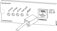
Figure 2 shows a Supervisor Engine with an RJ-45 console port connector.
Figure 2: Catalyst 6500/6000 Supervisor Engine I Front Panel 
Console Port Mode Switch
Some Supervisor Engine console ports have a mode switch. The console port mode switch (Catalyst 5500/5000 and Catalyst 6500/6000 Supervisor Engines only) has two modes. Mode 1 is the "in" position (default), and Mode 2 is the "out" position. Mode 1 allows you to connect either a terminal or modem to the console port with use of the default rollover cable. The cable comes with the accessory kit.
You might not have the accessory kit (see Cables and Connectors) or you might have misplaced the rollover cable. In this case, Mode 2 gives you the option to use a standard RJ-45 straight-through cable to connect a terminal.
The console port mode switch is in (by default), which is the position that the Step-by-Step procedure of this document uses. For more information on signaling and pinouts for these two modes specifically, refer to the document Connector and Cable Specifications.
Console Port Speed
The set system baud command changes the speed of console ports of some switches (that run CatOS). You can change the speed to up to 38,400 bits per second (bps). However, you should not perform this action.
First, some switch console ports do not support speeds higher than 9600 bps. For the purposes of this document, you should leave the console port speed at the default 9600 bps.
set system modem Command
Catalyst 4500/4000, 5500/5000, and 6500/6000 switches that run CatOS have the optional command set system modem {enable | disable}. This command enables hardware flow control (use of Request to Send [RTS]/Clear to Send [CTS] signals) on the console port. You configure the command on both sides of the connection. (See your modem manual for the Hayes-compatible AT ["attention"] commands.)
Hardware flow control is useful to protect data loss at higher baud rates. However, since you should leave the console port speed at the default of 9600, hardware flow control is not necessary. For the purposes of this document, you should leave this command at the default setting of set system modem disable.
Set a Logout Time or EXEC Timeout
One problem with console ports is that console ports do not support RS232 modem control. When an EXEC session terminates, the modem connection does not drop automatically. You must drop the connection manually.
Another problem is that, if the connection drops during an EXEC session, the session does not automatically reset. The failure to reset causes a potential security hole.
These problems are two of the risks and limitations inherent in the use of console ports for dial-up. For more information on the risks and limitations of the console port for modem connectivity, refer to the Console Port Issues section of the Modem-Router Connection Guide. In order to minimize these risks, follow these procedures:
-
If you run CatOS, issue the set logout minutes command and configure the timeout to be short. This command terminates an EXEC session after a period of idle time that you have configured. You can set logout time on a Catalyst 6500/6000 to between 0 and 10,000 minutes. The default is 20 minutes. This example shows the configuration:
Console>(enable) set logout 5
Sessions will be automatically logged out after 5 minutes of idle time.
Console>(enable)

!--- After 5 minutes of idle time, the user is logged out.

Automatic logout...
Session Disconnected...

Cisco Systems Console        Fri Apr 19 2002, 19:13:02

Enter password:
-
If you run Cisco IOS Software, use the exec-timeout minutes [seconds] command. This command terminates an EXEC session after a period of idle time that you have configured. On a Catalyst 6500/6000 that runs Cisco IOS Software, you can set the minutes to between 0 and 35,791 minutes and the seconds to between 0 and 2,147,483 seconds. This example shows the configuration:
Console-Native(config)#line con 0
Console-Native(config-line)#exec-timeout 4 30

!--- The commands sets logout for the EXEC session to occur after 4 minutes !--- and 30 seconds of idle time.
-
Even after you configure logouts, make it a practice to exit from enable mode and disconnect your modem session when you finish. If you require even tighter security, use a modem that provides a password prompt.
Configuration Recommendations
Some console ports provide DTE signaling while others provide DCE. In order to avoid confusion, use these configuration scenarios:
-
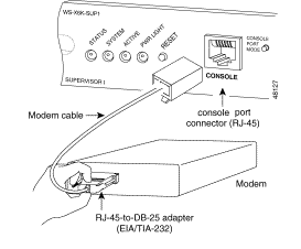
If the switch has an RJ-45 port, use a rolled RJ-45-to-RJ-45 cable (CAB-500RJ=) and an RJ-45-to-DB-25 male adapter (CAB-25AS-MMOD) to connect the rolled cable to the DB-25 port on the modem.
-
If the switch has a DB-25 port, use a rolled RJ-45-to-RJ-45 cable (CAB-500RJ=) with DB-25-to-RJ-45 adapters that are marked "Modem" (CAB-25AS-MMOD) on both ends. Instead of this combination, you can also use a null modem DB-25F-to-DB25M RS232 cable.
Other combinations of cables and adapters are possible. You can also make your own cables, although this is not recommended. For more information on console port signaling, pinouts, and cabling for all Catalyst switches, refer to the document Connecting a Terminal to the Console Port on Catalyst Switches.
Terminal Settings
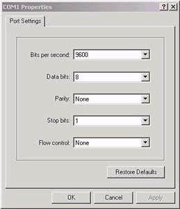
You use a terminal emulation program such as Microsoft Windows HyperTerminal to communicate with the modem on your PC COM port. The COM port settings are 9600, 8, N, 1, as in this example:

Step-by-Step Procedure To Configure Modem
This section provides the step-by-step procedure to set up modem connectivity on the console port. First, this section provides a high-level overview of the tasks necessary for modem connectivity:
-
Configure the modem for console connectivity. Since the the console port lacks reverse Telnet capability, set the modem initialization string (init string) prior to the connection of the modem to the console port of the switch.
-
Connect the modem to the console port of the switch.
-
Configure the switch to accept calls that arrive.
After the correct configuration of the terminal emulation program, connect the modem to the PC COM port. Then, set an init string. This step-by-step procedure uses a Catalyst 6500/6000 Supervisor Engine I, but you can substitute any Catalyst Supervisor Engine or fixed configuration switch. (See the Components Used section of this document for a list of switches.) Be sure to keep in mind the Configuration Recommendations of this document.
-
Connect the modem to a PC.
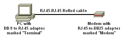
Attach an RJ-45-to-DB-9 adapter marked "Terminal" to the COM port of the PC. From the RJ-45 end of the adapter, connect a flat rolled RJ-45-to-RJ-45 cable (CAB-500RJ= ). You also need an RJ-45-to-DB-25 adapter marked "Modem" (CAB-25AS-MMOD) to connect the rolled cable to the DB-25 port on the modem.

-
In your HyperTerminal window, enter "AT ".
You should receive "OK" in return. The modem responds to a Hayes-compatible command which verifies that the modem communicates successfully with the PC COM port. In the init strings to follow, the result code feature is disabled because the feature can interfere with the switch.
At this stage, however, this verification is a good test to see if the modem and terminal communicate. If you do not receive an "OK", turn the modem off, then turn the modem back on to restore factory defaults. Verify that the cabling and adapters are fine. Your modem might also have external dual in-line package (DIP) switches which affect result code settings. You can also try to use the AT&F modem command to reset the modem to the factory default.
Note: Always consult your modem manual to verify the use of the Hayes-compatible command set and the configuration of DIP switches (if there are any).
-
Set a specific init string for your vendor modem.
The effect of each init string is to:
-
Set the modem to ignore DTR and assert autoanswer. The associated Hayes-compatible commands are AT&D0 and ATS0=1, respectively.
-
Disable DIP switch settings.
-
Silence the modem. This action eliminates result codes and local echoes that confuse the Catalyst Supervisor Engine console. The associated Hayes-compatible commands are ATQ1 and ATE0, respectively.
Note: Keep in mind that you are unable to see the commands you type into the modem from this point on (since the disable of local echo).
-
If possible, lock the modem DTE rate at 9600 baud rate. (Turn off negotiation.) This rate should match the speed on the console port of the switch. The rate is the speed at which the modem communicates with the switch and not the speed between the two modems across the telephone network. For older modems, adjust speed levels with DIP switches or your command set. (Refer to your modem manual.) Some modern modems do not have this setting. In this case, you should hard set the modem speed to 9600 with use of the appropriate init string that you obtained from the modem manufacturer.
-
Disable flow control. The Hayes-compatible command is AT&K0. For US Robotics (USR) modems, use AT&H0&I&R1.
-
Store these settings with the AT&W command. This command ensures that you preserve the settings at modem power cycle. (You write the settings into the registers.)
Four init strings underwent tests for this document. These init strings work with Catalyst series switches. Other vendor modems may work as well, but only these modems have been tested thus far.
Enter one of the init strings from these tables in the HyperTerminal window. Or, consult the manual for your modem and enter an equivalent init string.
Note: Refer to your modem documentation for the specific commands.
3COM/USRDescription Hayes-Compatible Command Factory defaults &F0 No result codes Q1 No echo E0 Autoanswer S0=1 No flow control &H0&I&R1 Lock DTE speed &B1 Ignore DTR &D0 Write config to NVRAM &W Init String: AT&F0Q1E0S0=1&H0&I&R1&B1&D0&W Note: If this init string does not work, see the Alternate Procedure for USR Modem section of this document.
ZOOM
HAYES ACCURADescription Hayes-Compatible Command Factory defaults &F0 No result codes Q1 No echo E0 Autoanswer S0=1 No flow control &K0 Ignore DTR &D0 Write config to NVRAM &W Init String: AT&F0Q1E0S0=1&K0&D0&W
ACTIONTECDescription Hayes-Compatible Command Factory defaults &F0 No result codes Q1 No echo E0 Modem speed 9600 S37=9 Autoanswer S0=1 No flow control &K0 Ignore DTR &D0 Write config to NVRAM &W Init String: AT&F0Q1E0S0=1S37=9&K0&D0&W Description Hayes-Compatible Command Factory defaults &F0 No result codes Q1 No echo E0 No flow control &K0 Autoanswer S0=1 Ignore DTR &D0 Write config to NVRAM &W Init String: AT&F0Q1E0S0=1&K0&D0&W -
-
Unplug the rolled RJ-45 cable from the PC terminal adapter and attach it to the console port of the Supervisor Engine.
At this point, the Catalyst switch should be dial-accessible.

-
Remember to configure logouts or EXEC timeouts as appropriate.
See the Set a Logout Time or EXEC Timeout section of this document. Disconnect your HyperTerminal session when you finish.
Alternate Procedure for USR Modem
Complete these steps:
-
Set DIP switches 3 and 8 to Down, and all others to Up.
Refer to Dip Switches for more information.
-
Connect the modem to PC.
-
Run HyperTerminal and connect to the modem at 9600 baud.
-
Send init string at&fs0=1&c1&h0&d2&r2&b1&m4&k0&n6&w.
You can also try these other init strings:
-
at&f0s0=1&b0&n6&u6&m4&k0&w
-
AT&FS0=1&C1&D3&B1&K1&M4&W
-
-
Set DIP switches 1, 4, and 8 to Down, and all others to Up.
-
Connect the modem to the console port of the switch with the appropriate cable.


 Feedback