Troubleshooting the Catalyst 5000 Route Switch Module (RSM) and InterVLAN Routing
Available Languages
Contents
Introduction
This document provides information on troubleshooting interVLAN routing with a Route Switch Module (RSM) on a Catalyst 5000 family switch. When it comes to troubleshooting the RSM, the first thing to do is to think of it as a simple external router. It is very seldom that a RSM-specific issue is causing a problem when interVLAN routing is concerned. Therefore, this document only covers the two main areas where this could occur:
-
RSM Hardware-Related Issues: This document introduces the RSM architecture and gives details on the additional RSM-related counters to track.
-
InterVLAN Configuration Specific Issues (mostly related to the interaction between routers and switches): This also applies to other internal routers (such as the Multilayer Switch Feature Card [MSFC], Route Switch Feature Card [RSFC], 8510CSR, and so on), and often to external routers.
Note: This document does not cover configuring interVLAN routing on Catalyst 4000, 5000, and 6000 switches. For those details, refer to these documents:
-
Configuration and Overview of the Router Module for the Catalyst 4500/4000 Family (WS-X4232-L3)
-
Configuring the Module for InterVLAN Routing section of Installation and Configuration Note for the Catalyst 4000 Layer 3 Services Module
This document does not cover basic routing protocol troubleshooting, or multilayer switching (MLS)-related issues.
Prerequisites
Requirements
There are no specific requirements for this document.
Components Used
This document is not restricted to specific software and hardware versions.
Conventions
For more information on document conventions, refer to the Cisco Technical Tips Conventions.
What Is InterVLAN Routing?
Before discussing interVLAN routing, this document focuses on the VLAN concept. This is not a theoretical discussion on the need for VLANs, but simply discusses how VLANs operate on a switch. When you create VLANs on your switch, it is as though you split your switch into several virtual bridges, with each one only bridging ports belonging to the same VLAN.
This diagram represents a switch with nine ports assigned to three different VLANs:
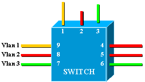
This is exactly equivalent to the following network, which consists of three independent bridges:
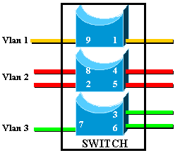
In the switch, there are three different bridges, due to each VLAN creating a separate bridge. Since each VLAN creates a separate Spanning Tree Protocol (STP) instance, STP maintains three different forwarding tables.
Using the second diagram, it becomes obvious that although connected to the same physical device, ports belonging to different VLANs cannot communicate directly at Layer 2 (L2). Even if possible, this would not be appropriate. For example, if you connected port 1 to port 4, you would simply merge VLAN1 to VLAN2. In this case, there would be no reason to have two separate VLANs.
The only connectivity that you want between VLANs is achieved at Layer 3 (L3) by a router. This is interVLAN routing. To further simplify the diagrams, VLANs are represented as different physical Ethernet segments, as you are not really interested in the specific bridging functions provided by the switch.
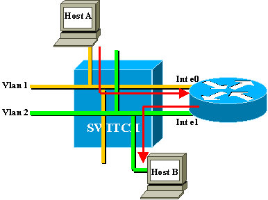
In this diagram, the two VLANs are considered as two different Ethernet segments. InterVLAN traffic needs to go through the external router. If host A wants to communicate with host B, it typically uses the router as a default gateway.
RSM Architecture
Logical Architecture
You can view a RSM as an external router that has several interfaces directly connected into the different VLANs of a Catalyst 5000 switch.
Instead of being called an Ethernet interface, these interfaces are named according to the VLAN that they connect to. (Interface VLAN1 is directly connected to VLAN1, and so on.)
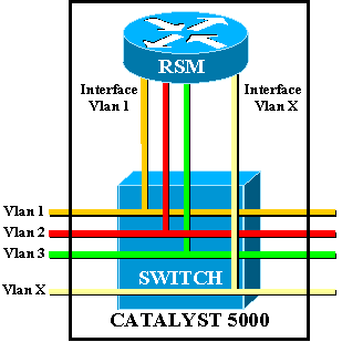
Architecture Implemented
The RSM is a Cisco 7500 Route Switch Processor (RSP) router inside of a Catalyst 5000 line card. You do not need to know a great deal about the architecture of the card to configure and troubleshoot it. However, having an idea of how the RSM is built helps to understand how it is different from a normal external router. This knowledge is especially important when introducing the show controller c5ip command.
This diagram locates the main components in the RSM line card:
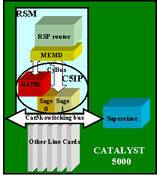
Catalyst 5000 Interface Processor
The Catalyst 5000 Interface Processor (C5IP) is the part of the RSM that emulates a Catalyst 7500 system IP, with the Catalyst 5000 switching bus as the network interface. The C5IP includes an R4700 processor along with two SAGE Application-Specific Integrated Circuits (ASICs), which are responsible for access to the Catalyst 5000 switching bus.
SAGE
These two ASICs get packets from/to the switching bus and buffer them. Along with the data in the packet, they also get an index identifying the destination of the packet in the switch.
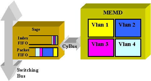
The destination VLAN interface is not determined from the content of the packet itself, but is derived from the index. The packet and the index are first stored in two different FIFOs inside the SAGE. The index is read and the necessary shared memory is reserved in the area of the destination VLAN. The packet is then copied in the memory device (MEMD), using a Direct Memory Access (DMA) to the SAGE.
Two SAGEs working in parallel to communicate between the router and the switching bus can lead to an out of sequence packet delivery. (For example, a large packet received on SAGE0 could be transmitted after a small packet received later by SAGE1.) In order to avoid this, each VLAN is statically assigned to a given SAGE. This is done automatically at startup. (According to the router, a VLAN is associated to one of the two DMA channels, each of them leading to a SAGE.) Packets from a given VLAN are always delivered in sequence.
MEMD
MEMD is the shared memory used by the router to send and receive packets. Each configured VLAN interface on the RSM is allocated a part of the available shared memory. The more VLAN interfaces configured, the less shared memory per interface. VLAN interfaces hold their part of the shared memory even when disabled or shut down. Only administratively adding or removing a VLAN interface triggers a new repartition of the MEMD among VLAN interfaces.
RSM-Specific Troubleshooting
The main RSM-specific issues that are not covered in the usual Cisco IOS® router documentation are problems with accessing the RSM, and also performance issues.
Accessing the RSM
The RSM can be accessed in three different ways:
Telnet to the RSM
In order to Telnet into the RSM, you need to know the IP address assigned to one of its VLAN interfaces. The Telnet session works exactly the same as if you were trying to connect to a normal Cisco IOS router. You may need to assign a password to the vty in order to achieve Telnet and gain enable access.
This example shows a Telnet session from a Supervisor Engine to a RSM, in which the VLAN1 IP address is 10.0.0.1:
sup> (enable) telnet 10.0.0.1
Trying 10.0.0.1...
Connected to 10.0.0.1.
Escape character is '^]'.
User Access Verification
Password: rsm> enable
Password: rsm# show run

!--- Output suppressed.

!
hostname rsm
!
enable password ww

!--- An enable password is configured.

!

!--- Output suppressed.

line vty 0 4
password ww
login

!--- Login is enabled. A password must be configured on the vty.

!
end
This is similar to other external router Cisco IOS configurations.
Session In to the RSM from the Switch Supervisor
Using the session x command from the Supervisor Engine connects you to the RSM in slot x.
The method is the same as the previous one: the RSM has a hidden VLAN0 interface that has an IP address 127.0.0.(x+1), where x is the slot where the RSM is installed. The session command issues a hidden Telnet session to this address.
Note: This time, vty and enable passwords do not have to be in the configuration to gain full access to the RSM.
sup> (enable) show module
Mod Slot  Ports      Module-Type Model          Status
--- ---- ----- ------------------------- -------------------
1     1    0     Supervisor III WS-X5530          ok
2     2          Route Switch Ext Port
3     3    1     Route Switch WS-X5302            ok
4     4   24     10/100BaseTX Ethernet WS-X5225R  ok
5     5   12     10/100BaseTX Ethernet WS-X5203   ok

!--- Output suppressed.

sup> (enable) session 3
Trying Router-3...
Connected to Router-3.
Escape character is '^]'.
rsm> enable
rsm#
You use the Supervisor Engine command show module to identify the slot in which your RSM is installed in the switch. You can directly access it by using the session command.
Direct Console Connection
The system console port on the RSM is a DB-25 receptacle DCE port for connecting a data terminal, which allows you to configure and communicate with your system. Use the console cable provided to connect the terminal to the console port on the RSM. The console port is located on the RSM next to the auxiliary port and is labeled console.
Before connecting the console port, check your terminal documentation to determine the baud rate of the terminal you will be using. The baud rate of the terminal must match the default baud rate (9600 baud). Set up the terminal as: 9600 baud, eight data bits, no parity, and two stop bits (9600,8N2).
Cannot Access the RSM
The RSM can be isolated for several reasons. Even without being able to connect to it, there are some signs of life you can check from the outside:
-
Check the status of the LEDS on the RSM:
-
CPU Halt LED is OFF—System detected a processor hardware failure.
-
Orange STATUS LED—Module disabled, test in progress, or system boot in progress.
-
-
Check the Supervisor Engine to see if the switch can see the RSM. To do this, issue the show module command:
sup> (enable) show module
Mod Slot Ports    Module-Type Model              Status
--- ---- ----- -------------------------  -------------------
1    1    0    Supervisor III WS-X5530             ok
2    2         Route Switch Ext Port
3    3    1    Route Switch WS-X5302               ok
4    4   24    10/100BaseTX Ethernet WS-X5225R     ok
5    5   12    10/100BaseTX Ethernet WS-X5203      ok

!--- Output suppressed.
Never declare your RSM dead before having attempted the console connection. As you have seen, both session and Telnet access are relying on an IP connection to the RSM. If the RSM is booting or stuck in ROMMON mode, for example, you cannot Telnet or session to it. This is quite normal, however.
Even if the RSM appears to be faulty, try to connect to its console. By doing this, you may be able to see some error messages, which will be displayed there.
Performance Issues
Most of the performance issues that are related to the RSM can be troubleshooted in exactly the same way as with a normal Cisco IOS router. This section focuses on the specific part of the RSM implementation that is the C5IP. The command show controller c5ip can give information regarding the operation of the C5IP. This output describes some of its most important fields:
RSM# show controllers c5ip
DMA Channel 0 (status ok)
51 packets, 3066 bytes
One minute rate, 353 bits/s, 1 packets/s
Ten minute rate, 36 bits/s, 1 packets/s
Dropped 0 packets
Error counts, 0 crc, 0 index, 0 dmac-length, 0 dmac-synch, 0 dmac-timeout
Transmitted 42 packets, 4692 bytes
One minute rate, 308 bits/s, 1 packets/s
Ten minute rate, 32 bits/s, 1 packets/s
DMA Channel 1 (status ok)
Received 4553 packets, 320877 bytes
One minute rate, 986 bits/s, 2 packets/s
Ten minute rate, 1301 bits/s, 3 packets/s
Dropped 121 packets
0 ignore, 0 line-down, 0 runt, 0 giant, 121 unicast-flood
Last drop (0xBD4001), vlan 1, length 94, rsm-discrim 0, result-bus 0x5
Error counts, 0 crc, 0 index, 0 dmac-length, 0 dmac-synch, 0 dmac-timeout
Transmitted 182 packets, 32998 bytes
One minute rate, 117 bits/s, 1 packets/s
Ten minute rate, 125 bits/s, 1 packets/s
Vlan Type DMA Channel Method
1 ethernet 1 auto
2 ethernet 0 auto
Inband IPC (status running)
Pending messages, 0 queued, 0 awaiting acknowledgment
Vlan0 is up, line protocol is up
Hardware is Cat5k Virtual Ethernet, address is 00e0.1e91.c6e8 (bia 00e0.1e91.c6e8)
Internet address is 127.0.0.4/8
MTU 1500 bytes, BW 100000 Kbit, DLY 100 usec,
reliability 255/255, txload 1/255, rxload 1/255
Encapsulation ARPA, loopback not set
ARP type: ARPA, ARP Timeout 04:00:00
Last input 00:00:00, output 00:00:00, output hang never
Last clearing of "show interface" counters never
Queueing strategy: fifo
Output queue 0/40, 0 drops; input queue 0/75, 0 drops
5 minute input rate 0 bits/sec, 1 packets/sec
5 minute output rate 0 bits/sec, 0 packets/sec
53 packets input, 3186 bytes, 0 no buffer
Received 0 broadcasts, 0 runts, 0 giants, 0 throttles
0 input errors, 0 CRC, 0 frame, 0 overrun, 0 ignored
RSM#
DMA Channel 0/1
The RSP router inside the RSM is communicating to the switch via two distinct DMA channels (going to the two SAGE ASICs). Each VLAN interface is automatically associated with one of these DMA channels. The show controllers c5ip command displays information on each one in two distinct sections.
Received/Transmitted
These statistics help identify the load on the different DMA channels. Look for a DMA channel that is steadily overloaded compared to the others. This may occur if all traffic-intensive VLANs are assigned to the same DMA channel. If necessary, you can manually assign VLAN interfaces to a specific DMA channel using the interface command dma-channel.
Dropped
This indicates the number of packets that the RSM received but dropped. This happens when the index received along with the packet does not give the RSM as the specific destination of the packet.
Error Counts
-
CRC —Cyclic redundancy cycle (CRC) errors occur when a bad CRC is detected by the RSM. There should not be any packets with bad CRCs on the backplane, and the RSM detecting these indicates that some line cards or other backplane-attached device is not working properly.
Note: CRC errors can also come from a remote device attached via an ISL trunk. Most Catalyst line cards do not check the CRC of a packet they receive from the backplane and forward on a trunk.
-
index —Index errors occur when the index is not accurate. The C5IP is not aware of why it received this packet. This also increments the Dropped counter.
-
dmac-length —These errors occur when the C5IP interface prevented the SAGE ASIC from overrunning a maximum transmission unit (MTU) size which, if undetected, would have corrupted the router shared memory.
-
dmac-synch —If a SAGE ASIC drops a packet, the packet FIFO and index FIFO become out of synch. If this error occurs, it is automatically detected and the dmac-synch counter is incremented. It is unlikely for this to occur, but if it does, performance impact is extremely low.
-
dmac-timeout —This counter was added to the show controllers c5ip command in Cisco IOS Software Releases 11.2(16)P and 12.0(2). It increments when a DMA transfer does not complete within the maximum time required for the longest possible transfer. It indicates a hardware fault, and a RSM showing a nonzero value for this counter is a good candidate for replacement.
-
ignore —Ignores occur when the router runs out of MEMD buffers for input packets. This happens when the CPU is not processing packets as fast as they are coming in. This is likely due to whatever is keeping the CPU busy.
-
line-down —Line-down indicates that packets destined to a line protocol down VLAN were dropped. The C5IP received a packet for a VLAN interface that it believes to be down. This should not happen, since the switch should stop forwarding packets to a RSM interface that is down. Yet, you may see a few when an interface goes down, due to timing between the RSM declaring the interface down and the switch being notified.
-
runt/giant —This counter tracks invalid-size packets.
-
unicast-flood —Unicast-flood packets are packets sent to a specific MAC address. The Catalyst 5000 Content Addressable Memory (CAM) table does not know what port the MAC address is located on, so it floods the packet to all ports on the VLAN. The RSM also receives these packets, but unless it is configured for bridging on that VLAN, it is not interested in packets that do not match its own MAC address. The RSM throws these packets away. This is the equivalent of what happens on a real Ethernet interface in the Ethernet interface chip, which is programmed to ignore packets for other MAC addresses. In the RSM, this is done in the C5IP software. Most of the dropped packets are unicast-flood packets.
-
Last drop —This counter reveals specific information about the last dropped packet. This is low-level information that is out of the scope of this document.
VLAN Distribution Among DMA Channels
Here is part of the output of the show controllers c5ip command on a RSM having ten VLAN interfaces configured:
Vlan Type DMA Channel Method
1 ethernet 1 auto
2 ethernet 0 auto
3 ethernet 1 auto
4 ethernet 0 auto
5 ethernet 1 auto
6 ethernet 0 auto
7 ethernet 1 auto
8 ethernet 0 auto
9 ethernet 1 auto
10 ethernet 0 auto
This output shows which DMA channel a given VLAN interface is assigned to. You can see that odd VLANs go to channel 0, whereas even VLANs are linked to channel 1. If necessary, you can hard code this correspondence using the interface configuration command dma-channel. This example shows how to assign the interface VLAN1 of a RSM to DMA channel 0:
RSM# show controllers c5ip

!--- Output suppressed.

Vlan Type DMA Channel Method
1 ethernet 1 auto
2 ethernet 0 auto

!--- Output suppressed.

RSM# configure terminal
Enter configuration commands, one per line. End with CNTL/Z.
RSM(config)# interface vlan 1
RSM(config-if)# dma-channel 0
RSM(config-if)# ^Z
RSM#
RSM# show controllers c5ip

!--- Output suppressed.

Vlan Type DMA Channel Method
1 ethernet 0 configured
2 ethernet 0 auto

!--- Output suppressed.
VLAN0 Information
The main purpose of VLAN0 is to ensure effective communication to the Supervisor Engine of the switch. As this is a hidden interface, you cannot use a simple show interface vlan0 command to see statistics about it.
InterVLAN Routing Common Issues
Using the RSM Autostate Feature
A frequent issue with bridging is that a broken link can easily split a L2 network into two pieces. This situation should be avoided at any price, as a discontiguous network breaks the routing. (This is usually achieved by deploying redundant links.)
Consider this example, where a client attached on Switch 2 communicates with a server connected on Switch 1:
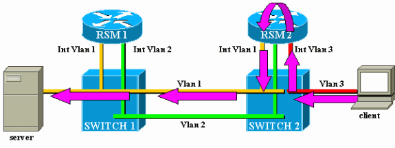
Consider the traffic from the client to the server only. Incoming traffic from the client in VLAN3 is routed by RSM2, which has a direct connection to the subnet of the server via its interface VLAN2. The purple arrows represent the path followed:
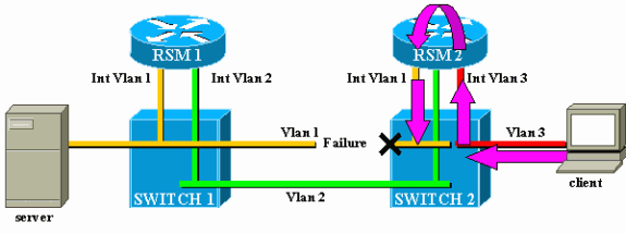
Suppose that the link between Switch 1 and Switch 2 breaks for VLAN1. The main problem here is that, from the point of view of RSM2, nothing changed in the network. RSM2 still has an interface directly attached to VLAN1, and it keeps forwarding traffic from the client to the server via this path. Traffic is lost in Switch 2, and connectivity between the client and the server is broken.
The RSM autostate feature was designed to address this. If there is no port up for a specific VLAN on a switch, the corresponding VLAN interface of the RSM is brought down.
In the case of the example, when the link in the VLAN between Switch 1 and Switch 2 fails, the only port in VLAN1 on Switch 2 is going down (link down). The RSM autostate feature disables the interface VLAN1 on RSM2. Now that interface VLAN1 is down, RSM2 can use a routing protocol to find another path for packets destined for the server and eventually forward traffic via another interface, as shown in this diagram:
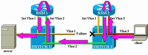
RSM autostate only works if there is no other port up in the VLAN. For instance, if you had another client in VLAN1 attached to Switch 2, or RSM in the chassis with an interface VLAN1 defined, the interface VLAN1 would not be disabled if the link between Switch 1 and Switch 2 failed. The traffic would then be disrupted again.
The RSM autostate feature is enabled by default. If needed, it can be manually disabled using the set rsmautostate command on the Supervisor Engine:
sup> (enable) show rsmautostate
RSM Auto port state: enabled
sup> (enable) set rsmautostate disable
sup> (enable) show rsmautostate
RSM Auto port state: disabled
Fall-Back Bridging
Fall-back bridging consists of bridging protocols between VLANs, while routing some others. If possible, you should avoid this kind of configuration and only use it during a transitory migration period. Typically, this is needed when you have segmented your network with different IP subnets, each on a different VLAN, but you want to keep bridging some old nonroutable protocols (local area transport [LAT], for example). In this case, you want to use your RSM as a router for IP, but as a bridge for other protocols. This is simply achieved by configuring bridging on the RSM interfaces, while keeping IP addresses. The following example illustrates a very simple network using fall-back bridging, along with the most common issue that can happen with this kind of configuration.
This very simple network is made of two VLANs, corresponding to two different IP subnets. Hosts in a given VLAN can use any of the two RSMs as a default gateway (or even both, using Hot Standby Router Protocol [HSRP]), and thus can communicate with hosts on the other VLAN. The network looks like this:

Both RSMs are also configured to bridge other protocols between their interfaces, VLAN1 and VLAN2. Suppose that you have a host offering LAT services and a client using them. Your network will look like this:

For this diagram, each Catalyst is split into two different bridges (one for each VLAN). You can see that bridging between the two VLANs resulted in a merger of the two VLANs. As far as bridged protocols are concerned, you only have one VLAN, and the LAT server and client can communicate directly. Of course, this also implies that you have a loop in the network and that STP has to block one port.
As you can see, a problem is going to arise from this blocking port. A switch is a pure L2 device and is not able to differentiate between IP and LAT traffic. Hence, if Switch 2 blocks one port, as in the above diagram, it blocks all types of traffic (IP, LAT, or other). Because of this, your network looks like this:

VLAN2 is split into two parts, and you have a discontiguous subnet 10.2.0.0. With this configuration, host 10.2.0.10 cannot communicate with host 10.2.0.20, although they are on the same subnet and VLAN.
The solution is to move the blocked port on the only device that can distinguish L2 and L3 traffic. That device is the RSM. There are two main ways to achieve this:
-
By Tuning STP Parameters: You need to increase the cost on one or several devices so that, eventually, the blocking port is located on RSM1 or RSM2. This method is not very flexible and implies a very strict STP configuration. Adding a switch or changing the bandwidth of a link (Fast EtherChannel or Gigabit Ethernet) may cause a complete rework of the tuning.
-
By Using a Different Spanning Tree Algorithm (STA) on the RSM: The switches only run the IEEE STA and are completely transparent to the DEC STP. If you configure DEC STP on both RSMs, they work as if they were directly connected together, and one of them will block. This diagram illustrates this:

Temporary Black Hole (ST Convergence)
Customers testing the speed of reconfiguration of their network in the event of failure often deal with configuration issues related to STP. Consider the following network, where a client accesses a server via two different paths. By default, traffic from the client to the server is routed via interface VLAN2 by RSM2:
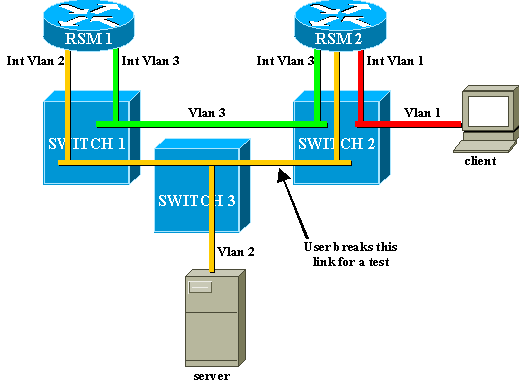
In order to perform a test, a user breaks the link between Switch 2 and Switch 3. Immediately, the corresponding port goes down, and the RSM autostate feature brings down the interface VLAN2 on RSM2. The directly connected route for the server disappears from the routing table of RSM2, which quickly learns a new route via RSM1. With efficient routing protocols like Open Shortest Path First (OSPF) or Enhanced Interior Gateway Routing Protocol (EIGRP), convergence is so fast that you hardly lose a ping during this operation.
In the event of failure, the switchover between the two paths (yellow VLAN2 and green VLAN3) has been immediate. If the user reestablishes the link between Switch 2 and Switch 3, however, the client experiences a loss of connectivity to the server for about 30 seconds.
The reason for this is also related to the STA. When running STA, a newly connected port first goes through the listening and learning stages before ending up in forwarding mode. During the first two 15-second stages, the port is up, but does not transmit traffic. This means that as soon as the link is connected, the RSM autostate feature immediately reenables interface VLAN2 on RSM2, but the traffic cannot go through until the ports on the link between Switch 2 and Switch 3 reach the forwarding stage. This explains the loss of temporary connectivity between the client and the server. If the link between Switch 1 and Switch 2 is not a trunk, you can enable the PortFast feature to skip the listening and learning stages and converge immediately.
Note: PortFast does not work on trunk ports. Refer to Using PortFast and Other Commands to Fix Workstation Startup Connectivity Delays for more information.
Conclusion
This document focuses on some RSM-specific issues, as well as some very common interVLAN routing issues. This information is only useful when all the normal Cisco IOS router troubleshooting procedures have been attempted. If half of the packets routed by a RSM are lost because of the wrong routing table, it does not help to try to interpret the DMA-channel statistics. Even the general interVLAN routing issues are advanced topics and do not occur very often. In most cases, considering your RSM (or any other integrated routing device inside a switch) as a simple external Cisco IOS router is enough to troubleshoot routing issues in a switched environment.
Related Information
Revision History
| Revision | Publish Date | Comments |
|---|---|---|
1.0 |
02-Sep-2005 |
Initial Release |

 Feedback