ASA 8.3 and Later: NTP with and without an IPsec Tunnel Configuration Example
Available Languages
Contents
Introduction
This document provides a sample configuration for synchronizing the Adaptive Security Appliance (ASA) clock with a network time server using Network Time Protocol (NTP). ASA1 communicates directly with the network time server. ASA2 passes NTP traffic through an IPsec tunnel to ASA1, which in turn forwards the packets to the network time server.
Refer to ASA/PIX: NTP with and without an IPsec Tunnel Configuration Example for an identical configuration on Cisco ASA with versions 8.2 and earlier.
Note: A router can also be used as an NTP server for synchronizing the ASA Security Appliance clock.
Prerequisites
Requirements
There are no specific requirements for this document.
Components Used
The information in this document is based on these software and hardware versions:
-
Cisco ASA with version 8.3 and later
-
Cisco Adaptive Security Device Manager (ASDM) version 6.x and later
Note: Refer to Allowing HTTPS Access for ASDM in order to allow the ASA to be configured by the ASDM.
The information in this document was created from the devices in a specific lab environment. All of the devices used in this document started with a cleared (default) configuration. If your network is live, make sure that you understand the potential impact of any command.
Conventions
Refer to the Cisco Technical Tips Conventions for more information on document conventions.
Configuration
Network Diagram
This document uses this network setup:
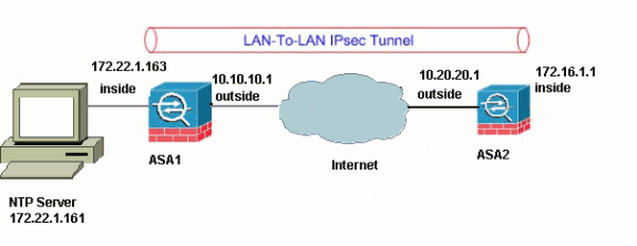
Note: The IP addressing schemes used in this configuration are not legally routable on the Internet. They are RFC 1918 ![]() addresses, which have been used in a lab environment.
addresses, which have been used in a lab environment.
VPN Tunnel ASDM Configuration
Complete these steps in order to create the VPN tunnel:
-
Open your browser and type https://<Inside_IP_Address_of_ASA> in order to access the ASDM on the ASA.
Be sure to authorize any warnings your browser gives you related to SSL certificate authenticity. The default username and password are both blank.
The ASA presents this window in order to allow the download of the ASDM application.
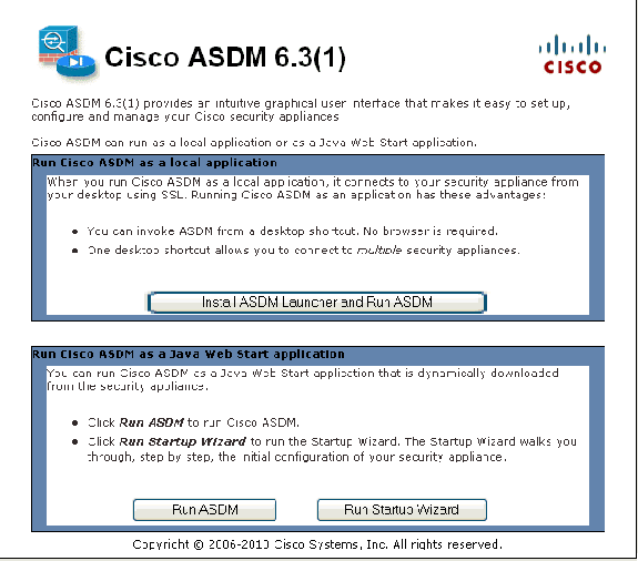
This example loads the application onto the local computer and does not run in a Java applet.
-
Click Download ASDM Launcher and Start ASDM in order to download the installer for the ASDM application.
-
Once the ASDM Launcher downloads, complete the steps directed by the prompts in order to install the software and run the Cisco ASDM Launcher.
-
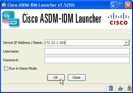
Enter the IP address for the interface you configured with the http - command, and a username and password if you specified one.
This example uses the default blank username and password:
-
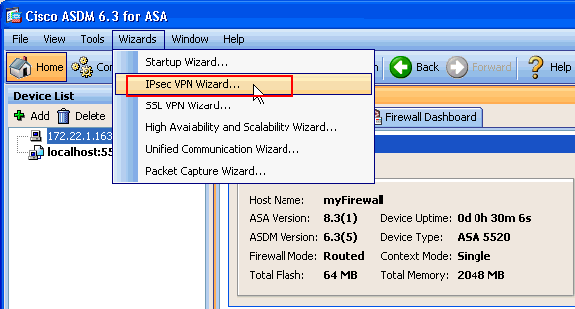
Run the VPN Wizard once the ASDM application connects to the ASA.
-
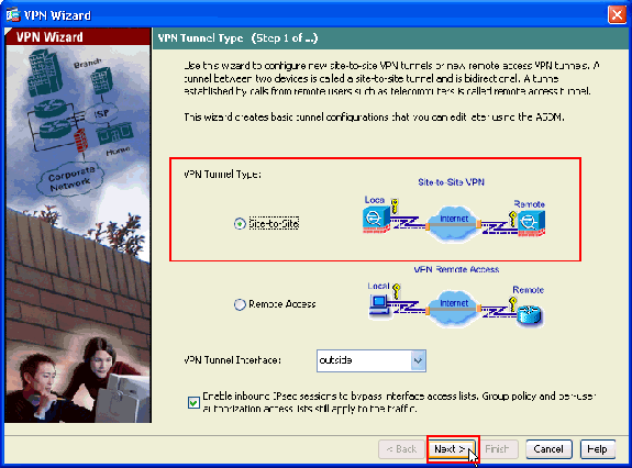
Choose Site-to-Site for the IPsec VPN Tunnel Type, and click Next.
-
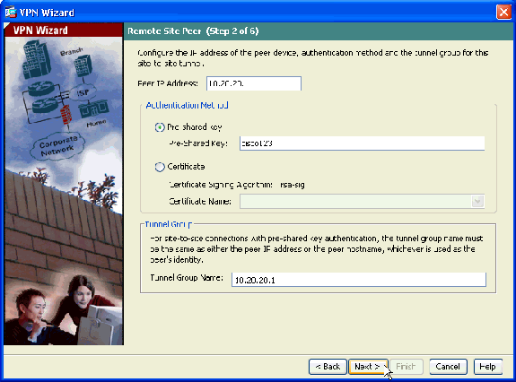
Specify the outside IP address of the remote peer. Enter the authentication information to use, which is the pre-shared key in this example:
-
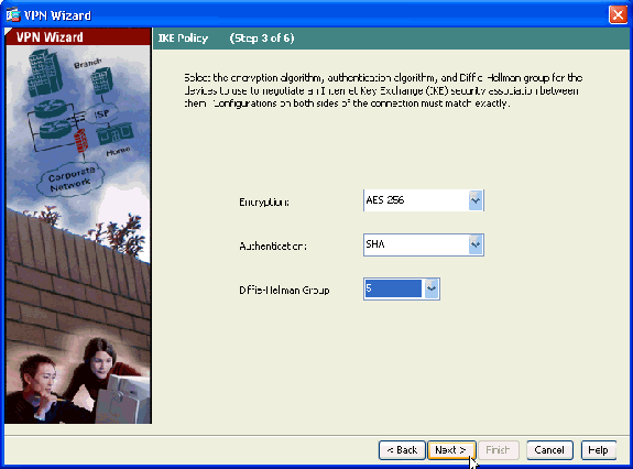
Specify the attributes to use for IKE, also known as Phase 1. These attributes must be the same on both sides of the tunnel.
-
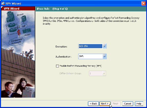
Specify the attributes to use for IPsec, also known as Phase 2. These attributes must match on both sides.
-
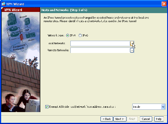
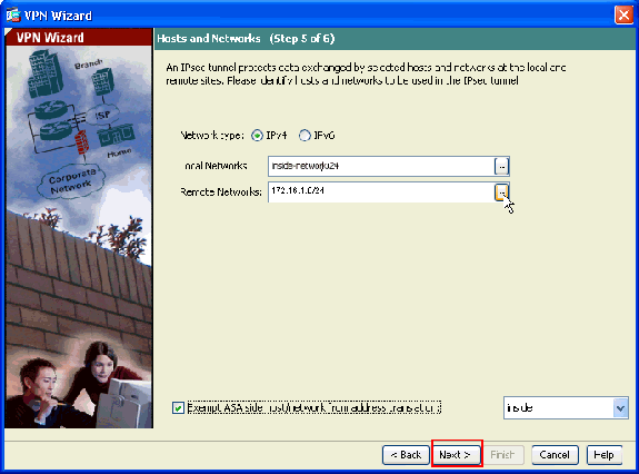
Specify the hosts whose traffic should be allowed to pass through the VPN tunnel. In this step, you have to provide the Local Networks and Remote Networks for the VPN Tunnel. Click the button next to Local Networks (as shown here) in order to choose the local network address from the drop-down menu:
-
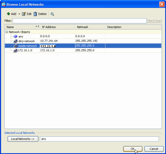
Choose the Local Network address, and click OK.
-
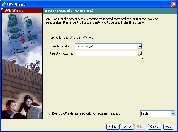
Click the button next to Remote Networks in order to choose the remote network address from the drop-down menu.
-
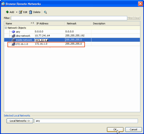
Choose the Remote Network address, and click OK.
Note: If you do not have the Remote Network in the list, then the network has to be added to the list. Click Add in order to do so.
-
Check the Exempt ASA side host/network from address translation checkbox in order to prevent the tunnel traffic from undergoing Network Address Translation. Click Next.
-
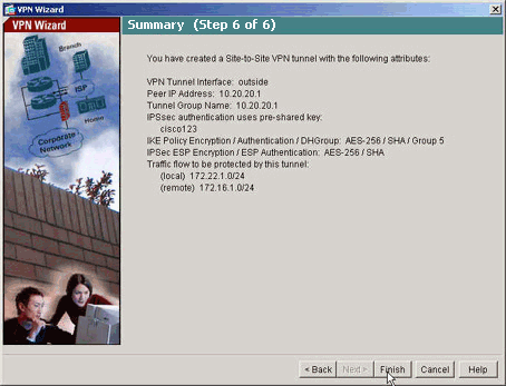
The attributes defined by the VPN Wizard are displayed in this summary. Double-check the configuration and click Finish when you are satisfied that the settings are correct.
NTP ASDM Configuration
Complete these steps in order to configure NTP on the Cisco Security Appliance:
-
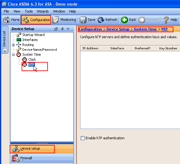
Choose Configuration in the ASDM home page.
-
Choose Device Setup > System Time > NTP in order to open the NTP configuration page of ASDM.
-
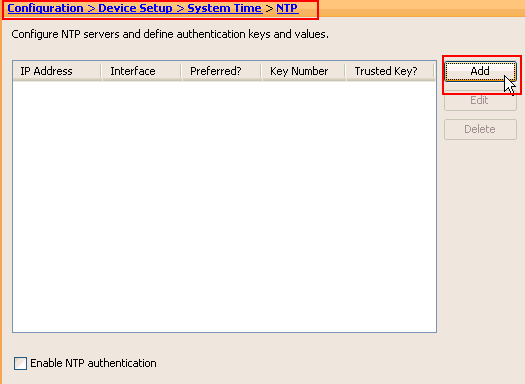
Click Add in order to add a NTP server and provide the required attributes such as IP address, Interface name (Inside or Outside), key number, and key value for Authentication in the new window that comes up. Click OK.
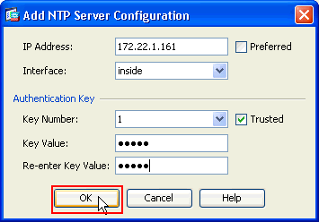
Note: The interface name should be chosen as inside for ASA1 and outside for ASA2.
Note: The ntp authentication key should be the same in ASA and the NTP server.
The Authentication attribute configuration in the CLI for ASA1 and ASA2 are shown here:
ASA1#ntp authentication-key 1 md5 cisco
ntp trusted-key 1
ntp server 172.22.1.161 key 1 source inside
ASA2#ntp authentication-key 1 md5 cisco
ntp trusted-key 1
ntp server 172.22.1.161 key 1 source outside
-
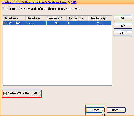
Click the checkbox Enable NTP Authentication and click Apply, which completes the NTP configuration task.
ASA1 CLI Configuration
| ASA1 |
|---|
ASA#show run : Saved ASA Version 8.3(1) ! hostname ASA1 domain-name default.domain.invalid enable password 8Ry2YjIyt7RRXU24 encrypted names ! interface Ethernet0 nameif outside security-level 0 ip address 10.10.10.1 255.255.255.0 !--- Configure the outside interface. ! interface Ethernet1 nameif inside security-level 100 ip address 172.22.1.163 255.255.255.0 !--- Configure the inside interface. ! !-- Output suppressed ! passwd 2KFQnbNIdI.2KYOU encrypted ftp mode passive dns server-group DefaultDNS domain-name default.domain.invalid access-list inside_nat0_outbound extended permit ip 172.22.1.0 255.255.255.0 172 .16.1.0 255.255.255.0 !--- This access list (inside_nat0_outbound) is used !--- with the nat zero command. This prevents traffic which !--- matches the access list from undergoing network address translation (NAT). !--- The traffic specified by this ACL is traffic that is to be encrypted and !--- sent across the VPN tunnel. This ACL is intentionally !--- the same as (outside_cryptomap_20). !--- Two separate access lists should always be used in this configuration. access-list outside_cryptomap_20 extended permit ip 172.22.1.0 255.255.255.0 172 .16.1.0 255.255.255.0 !--- This access list (outside_cryptomap_20) is used !--- with the crypto map outside_map !--- to determine which traffic should be encrypted and sent !--- across the tunnel. !--- This ACL is intentionally the same as (inside_nat0_outbound). !--- Two separate access lists should always be used in this configuration. pager lines 24 mtu inside 1500 mtu outside 1500 no failover asdm image flash:/asdm-631.bin !--- Enter this command to specify the location of the ASDM image. asdm history enable arp timeout 14400 object network obj-local subnet 172.22.1.0 255.255.255.0 object network obj-remote subnet 172.16.1.0 255.255.255.0 nat (inside,outside) 1 source static obj-local obj-local destination static obj-remote obj-remote !--- NAT 0 prevents NAT for networks specified in !--- the ACL inside_nat0_outbound. route outside 0.0.0.0 0.0.0.0 10.10.10.2 1 timeout xlate 3:00:00 timeout conn 1:00:00 half-closed 0:10:00 udp 0:02:00 icmp 0:00:02 timeout sunrpc 0:10:00 h323 0:05:00 h225 1:00:00 mgcp 0:05:00 timeout mgcp-pat 0:05:00 sip 0:30:00 sip_media 0:02:00 timeout uauth 0:05:00 absolute http server enable !--- Enter this command in order to enable the HTTPS server !--- for ASDM. http 172.22.1.1 255.255.255.255 inside !--- Identify the IP addresses from which the security appliance !--- accepts HTTPS connections. no snmp-server location no snmp-server contact !--- PHASE 2 CONFIGURATION ---! !--- The encryption types for Phase 2 are defined here. crypto ipsec transform-set ESP-AES-256-SHA esp-aes-256 esp-sha-hmac !--- Define the transform set for Phase 2. crypto map outside_map 20 match address outside_cryptomap_20 !--- Define which traffic should be sent to the IPsec peer. crypto map outside_map 20 set peer 10.20.20.1 !--- Sets the IPsec peer crypto map outside_map 20 set transform-set ESP-AES-256-SHA !--- Sets the IPsec transform set "ESP-AES-256-SHA" !--- to be used with the crypto map entry "outside_map". crypto map outside_map interface outside !--- Specifies the interface to be used with !--- the settings defined in this configuration. !--- PHASE 1 CONFIGURATION ---! !--- This configuration uses isakmp policy 10. !--- Policy 65535 is included in the config by default. !--- The configuration commands here define the Phase !--- 1 policy parameters that are used. isakmp enable outside isakmp policy 10 authentication pre-share isakmp policy 10 encryption aes-256 isakmp policy 10 hash sha isakmp policy 10 group 5 isakmp policy 10 lifetime 86400 isakmp policy 65535 authentication pre-share isakmp policy 65535 encryption 3des isakmp policy 65535 hash sha isakmp policy 65535 group 2 isakmp policy 65535 lifetime 86400 tunnel-group 10.20.20.1 type ipsec-l2l !--- In order to create and manage the database of connection-specific !--- records for ipsec-l2l—IPsec (LAN-to-LAN) tunnels, use the command !--- tunnel-group in global configuration mode. !--- For L2L connections, the name of the tunnel group MUST be the IP !--- address of the IPsec peer. tunnel-group 10.20.20.1 ipsec-attributes pre-shared-key * !--- Enter the pre-shared-key in order to configure the !--- authentication method. telnet timeout 5 ssh timeout 5 console timeout 0 ! class-map inspection_default match default-inspection-traffic ! ! policy-map global_policy class inspection_default inspect dns maximum-length 512 inspect ftp inspect h323 h225 inspect h323 ras inspect netbios inspect rsh inspect rtsp inspect skinny inspect esmtp inspect sqlnet inspect sunrpc inspect tftp inspect sip inspect xdmcp ! service-policy global_policy global !--- Define the NTP server authentication-key,Trusted-key !--- and the NTP server address for configuring NTP. ntp authentication-key 1 md5 * ntp trusted-key 1 !--- The NTP server source is to be mentioned as inside for ASA1 ntp server 172.22.1.161 key 1 source inside Cryptochecksum:ce7210254f4a0bd263a9072a4ccb7cf7 : end |
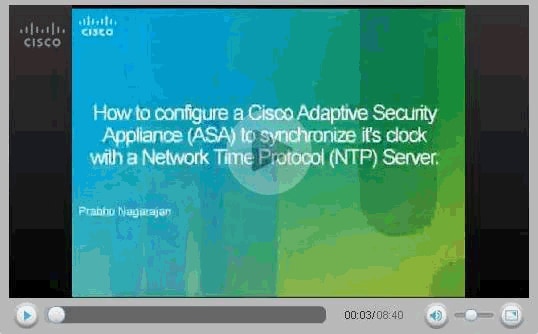
This video posted to the Cisco Support Community explains with a demo, the procedure to configure ASA as NTP client:
ASA2 CLI Configuration
| ASA2 |
|---|
ASA Version 8.3(1) ! hostname ASA2 domain-name default.domain.invalid enable password 8Ry2YjIyt7RRXU24 encrypted names ! interface Ethernet0 nameif outside security-level 0 ip address 10.20.20.1 255.255.255.0 ! interface Ethernet1 nameif inside security-level 100 ip address 172.16.1.1 255.255.255.0 ! passwd 2KFQnbNIdI.2KYOU encrypted ftp mode passive dns server-group DefaultDNS domain-name default.domain.invalid access-list inside_nat0_outbound extended permit ip 172.16.1.0 255.255.255.0 172 .22.1.0 255.255.255.0 !--- Note that this ACL is a mirror of the inside_nat0_outbound !--- ACL on ASA1. access-list outside_cryptomap_20 extended permit ip 172.16.1.0 255.255.255.0 172 .22.1.0 255.255.255.0 !--- Note that this ACL is a mirror of the outside_cryptomap_20 !--- ACL on ASA1. pager lines 24 mtu inside 1500 mtu outside 1500 no failover asdm image flash:/asdm-631.bin no asdm history enable arp timeout 14400 object network obj-local subnet 172.22.1.0 255.255.255.0 object network obj-remote subnet 172.16.1.0 255.255.255.0 nat (inside,outside) 1 source static obj-local obj-local destination static obj-remote obj-remote timeout xlate 3:00:00 timeout conn 1:00:00 half-closed 0:10:00 udp 0:02:00 icmp 0:00:02 timeout sunrpc 0:10:00 h323 0:05:00 h225 1:00:00 mgcp 0:05:00 timeout mgcp-pat 0:05:00 sip 0:30:00 sip_media 0:02:00 timeout uauth 0:05:00 absolute http server enable http 0.0.0.0 0.0.0.0 inside no snmp-server location no snmp-server contact crypto ipsec transform-set ESP-AES-256-SHA esp-aes-256 esp-sha-hmac crypto map outside_map 20 match address outside_cryptomap_20 crypto map outside_map 20 set peer 10.10.10.1 crypto map outside_map 20 set transform-set ESP-AES-256-SHA crypto map outside_map interface outside isakmp enable outside isakmp policy 10 authentication pre-share isakmp policy 10 encryption aes-256 isakmp policy 10 hash sha isakmp policy 10 group 5 isakmp policy 10 lifetime 86400 tunnel-group 10.10.10.1 type ipsec-l2l tunnel-group 10.10.10.1 ipsec-attributes pre-shared-key * telnet timeout 5 ssh timeout 5 console timeout 0 ! class-map inspection_default match default-inspection-traffic ! ! policy-map global_policy class inspection_default inspect dns maximum-length 512 inspect ftp inspect h323 h225 inspect h323 ras inspect netbios inspect rsh inspect rtsp inspect skinny inspect esmtp inspect sqlnet inspect sunrpc inspect tftp inspect sip inspect xdmcp ! service-policy global_policy global !--- Define the NTP server authentication-key,Trusted-key !--- and the NTP server address for configuring NTP. ntp authentication-key 1 md5 * ntp trusted-key 1 !--- The NTP server source is to be mentioned as outside for ASA2. ntp server 172.22.1.161 key 1 source outside Cryptochecksum:d5e2ee898f5e8bd28e6f027aeed7f41b : end ASA# |
Verify
This section provides information you can use in order to confirm that your configuration works properly.
Certain show commands are supported by the Output Interpreter Tool (registered customers only) , which allows you to view an analysis of show command output.
-
show ntp status - Displays the NTP clock information.
ASA1#show ntp status

Clock is synchronized, stratum 2, reference is 172.22.1.161
nominal freq is 99.9984 Hz, actual freq is 99.9983 Hz, precision is 2**6
reference time is ccf22b77.f7a6e7b6 (13:28:23.967 UTC Tue Dec 16 2008)
clock offset is 34.8049 msec, root delay is 4.78 msec
root dispersion is 60.23 msec, peer dispersion is 25.41 msec
-
show ntp associations [detail] - Displays the configured network time server associations.
ASA1#show ntp associations detail
172.22.1.161 configured, authenticated, our_master, sane, valid, stratum 1
ref ID .LOCL., time ccf2287d.3668b946 (13:15:41.212 UTC Tue Dec 16 2008)
our mode client, peer mode server, our poll intvl 64, peer poll intvl 64
root delay 0.00 msec, root disp 0.03, reach 7, sync dist 23.087
delay 4.52 msec, offset 9.7649 msec, dispersion 20.80
precision 2**19, version 3
org time ccf22896.f1a4fca3 (13:16:06.943 UTC Tue Dec 16 2008)
rcv time ccf22896.efb94b28 (13:16:06.936 UTC Tue Dec 16 2008)
xmt time ccf22896.ee5691dc (13:16:06.931 UTC Tue Dec 16 2008)
filtdelay =     4.52    4.68    4.61    0.00    0.00    0.00    0.00    0.00
filtoffset =    9.76    7.09    3.85    0.00    0.00    0.00    0.00    0.00
filterror =    15.63   16.60   17.58 14904.3 14904.3 14904.3 14904.3 14904.3
Troubleshoot
This section provides information you can use to troubleshoot your configuration.
Troubleshooting Commands
Certain show commands are supported by the Output Interpreter Tool (registered customers only) , which allows you to view an analysis of show command output.
Note: Before issuing debug commands, refer to Important Information on Debug Commands.
-
debug ntp validity - Displays NTP peer clock validity.
This is debug output from the key mismatch:
NTP: packet from 172.22.1.161 failed validity tests 10
 	  Authentication failed
-
debug ntp packet - Displays NTP packet information.
When there is no response from the server, only the NTP xmit packet is seen on the ASA with no NTP rcv packet.
ASA1# NTP: xmit packet to 172.22.1.161:
 leap 0, mode 3, version 3, stratum 2, ppoll 64
 rtdel 012b (4.562), rtdsp 0cb6 (49.652), refid ac1601a1 (172.22.1.161)
 ref ccf22916.f1211384 (13:18:14.941 UTC Tue Dec 16 2008)
 org ccf22916.f426232d (13:18:14.953 UTC Tue Dec 16 2008)
 rec ccf22916.f1211384 (13:18:14.941 UTC Tue Dec 16 2008)
 xmt ccf22956.f08ee8b4 (13:19:18.939 UTC Tue Dec 16 2008)
NTP: rcv packet from 172.22.1.161 to 172.22.1.163 on inside:
 leap 0, mode 4, version 3, stratum 1, ppoll 64
 rtdel 0000 (0.000), rtdsp 0002 (0.031), refid 4c4f434c (76.79.67.76)
 ref ccf2293d.366a4808 (13:18:53.212 UTC Tue Dec 16 2008)
 org ccf22956.f08ee8b4 (13:19:18.939 UTC Tue Dec 16 2008)
 rec ccf22956.f52e480e (13:19:18.957 UTC Tue Dec 16 2008)
 xmt ccf22956.f5688c29 (13:19:18.958 UTC Tue Dec 16 2008)
 inp ccf22956.f982bcd9 (13:19:18.974 UTC Tue Dec 16 2008)
Related Information
Revision History
| Revision | Publish Date | Comments |
|---|---|---|
1.0 |
25-Jan-2012 |
Initial Release |
Contact Cisco
- Open a Support Case

- (Requires a Cisco Service Contract)


 Feedback