PPPoA Baseline Architecture
Available Languages
Contents
Introduction
This document describes an end-to-end asymmetric digital subscriber line (ADSL) architecture using Point-to-Point Protocol over Asynchronous Transfer Mode (PPPoA). Although most deployments are based on the bridging architecture, PPPoA is gaining tremendous popularity and will form a larger portion of future ADSL deployments.
Assumption
The baseline architecture assumes the need for providing high speed Internet access and corporate access to the end subscriber using PPPoA as the core backbone. We will discuss this architecture based on private virtual channels (PVCs), the method used most often in current deployments. The architecture using switched virtual circuits (SVCs) will be discussed in a separate paper.
This document is based on existing deployments as well as inhouse tests of the architecture.
This document was written with the assumption that the reader is knowledgeable and familiar with the design considerations of a Network Access Provider (NAP) as described in the RFC1483 Bridging Baseline Architecture white paper.
Technology Brief
Point-to-Point Protocol (PPP) (RFC 1331) provides a standard method of encapsulating higher layer protocols across point-to-point connections. It extends the High-Level Data Link Control (HDLC) packet structure with a 16-bit protocol identifier that contains information about the content of the packet.
The packet contains three types of information:
-
Link Control Protocol (LCP) – negotiates link parameters, packet size, or type of authentication
-
Network Control Protocol (NCP) – contains information about higher layer protocols including IP and IPX, and their control protocols (IPCP for IP)
-
Data frames containing data
PPP over ATM adaptation layer 5 (AAL5) (RFC 2364) uses AAL5 as the framed protocol, which supports both PVC and SVC. PPPoA was primarily implemented as part of ADSL. It relies on RFC1483, operating in either Logical Link Control-Subnetwork Access Protocol (LLC-SNAP) or VC-Mux mode. A customer premises equipment (CPE) device encapsulates the PPP session based on this RFC for transport across the ADSL loop and the digital subscriber line access multiplexer (DSLAM).
Advantages and Disadvantages of PPPoA Architecture
PPPoA architecture inherits most of the advantages of PPP used in the Dial model. Some of the key points are listed below.
Advantages
-
Per session authentication based on Password Authentication Protocol (PAP) or Challenge Handshake Authentication Protocol (CHAP). This is the greatest advantage of PPPoA as authentication overcomes the security hole in a bridging architecture.
-
Per session accounting is possible, which allows the service provider to charge the subscriber based on session time for various services offered. Per session accounting enables a service provider to offer a minimum access level for minimal charge and then charge subscribers for additional services used.
-
IP address conservation at the CPE. This allows the service provider to assign only one IP address for a CPE, with the CPE configured for network address translation (NAT). All users behind one CPE can use a single IP address to reach different destinations. IP management overhead for the Network Access Provider/Network Services Provider (NAP/NSP) for each individual user is reduced while conserving IP addresses. Additionally, the service provider can provide a small subnet of IP addresses to overcome the limitations of port address translation (PAT) and NAT.
-
NAPs/NSPs provide secure access to corporate gateways without managing end-to-end PVCs and using Layer 3 routing or Layer 2 Forwarding/Layer 2 Tunneling Protocol (L2F/L2TP) tunnels. Hence, they can scale their business models for selling wholesale services.
-
Troubleshooting individual subscribers. The NSP can easily identify which subscribers are on or off based on active PPP sessions, rather than troubleshooting entire groups as is the case with bridging architecture.
-
The NSP can oversubscribe by deploying idle and session timeouts using an industry standard Remote Authentication Dial-In User Service (RADIUS) server for each subscriber.
-
Highly scalable as we can terminate a very high number of PPP sessions on an aggregation router. Authentication, authorization, and accounting can be handled for each user using external RADIUS servers.
-
Optimal use of features on the Service Selection Gateway (SSG).
Disadvantages
-
Only a single session per CPE on one virtual channel (VC). Since the username and password are configured on the CPE, all users behind the CPE for that particular VC can access only one set of services . Users cannot select different sets of services, although using multiple VCs and establishing different PPP sessions on different VCs is possible.
-
Increased complexity of the CPE setup. Help desk personnel at the service provider need to be more knowledgeable. Since the username and password are configured on the CPE, the subscriber or the CPE vendor will need to make setup changes. Using multiple VCs increases configuration complexity. This, however, can be overcome by an autoconfiguration feature which is not yet released.
-
The service provider needs to maintain a database of usernames and passwords for all subscribers. If tunnels or proxy services are used, then the authentication can be done on the basis of the domain name and the user authentication is done at the corporate gateway. This reduces the size of the database that the service provider has to maintain.
-
If a single IP address is provided to the CPE and NAT/PAT is implemented, certain applications such as IPTV, which embed IP information in the payload, will not work. Additionally, if an IP subnet feature is used, an IP address also has to be reserved for the CPE.
Implementation Considerations for PPPoA Architecture
Key points to consider before implementing PPPoA architecture include:
-
The number of subscribers that will be serviced currently and in the future, as this affects the number of required PPP sessions.
-
Whether the PPP sessions are being terminated at the service provider?s aggregation router or forwarded to other corporate gateways or Internet Service Providers (ISPs).
-
Whether the service provider or the final service destination is providing the IP address to the subscriber?s CPE.
-
Whether the IP addresses provided are legal public or private. Is the CPE going to do NAT/PAT or will NAT be performed at the termination destination?
-
Profiles of end subscribers, residential users, small office home office (SOHO) customers,and telecommuters.
-
In the case of more than one user, whether all users need to reach the same final destination or service, or they all have different service destinations.
-
Is the service provider providing any value added services like voice or video? Does the service provider require all subscribers to first go to a particular network before reaching a final destination? When subscribers use SSG, are they going to use passthrough services, PPP Terminated Aggregation (PTA), a mediation device, or proxy?
-
How the service provider bills subscribers—based on a flat rate, per session usage, or services used.
-
Deployment and provisioning of CPEs, DSLAMs and aggregation points of presence (POPs).
-
The business model for the NAP. Does the model also include selling wholesale services like secure corporate access and value added services like voice and video? Are NAPs and NSPs the same entity?
-
The business model of the company. Is it comparable to an independent local exchange carrier (ILEC), a competitive local exchange carrier (CLEC) or an ISP?
-
The types of applications the NSP will offer to the end subscriber.
-
The anticipated upstream and downstream volume of data flow.
Keeping these points in mind, we will discuss how the PPPoA architecture will fit and scale to different business models for service providers and how the providers can benefit using this architecture.
Typical PPPoA Network Architecture
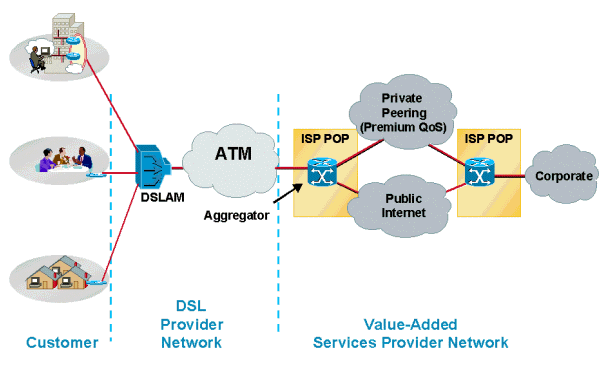
The following diagram shows a typical PPPoA network architecture. Customers using CPEs connect to the service provider's network through a Cisco DSLAM, which connects to a Cisco 6400 aggregator using ATM.
Design Considerations for PPPoA Architecture
In the "Implementation Considerations" section of this document, PPPoA architectures can be deployed using different scenarios depending on the service provider?s business model. In this section, we will discuss the different possibilities and considerations that service providers must keep in mind before deploying a solution.
Before deploying a PPPoA architecture and a particular solution for this architecture, it is essential to understand the service provider?s business model. Consider the services the service provider will offer. Will the service provider offer one service like high speed Internet access to its end subscribers or will it sell wholesale services to different ISPs and provide value-added services to those subscribers? Will the service provider offer all of them?
In the case of high speed Internet access in an environment where the NSP and the NAP are the same, the subscriber?s PPP sessions must be terminated in the deployed aggregation router. In this scenario, service providers need to consider how many PPP sessions can be terminated on a single router aggregation device, how the users are going to be authenticated, how they are going to perform accounting, and the path to the Internet once user sessions are terminated. Depending on the number of PPP sessions and subscribers, the aggregation router could be either a Cisco 6400 or a Cisco 7200. Today?s Cisco 6400 with 7 node route processers (NRPs) can terminate up to 14,000 PPP sessions. The Cisco 7200 is limited to 2,000 PPP sessions. These numbers will change with new releases. Please check the release notes and product documents for the exact number of sessions each aggregation router can support.
User authentication and accounting in these scenario is best handled by using an industry standard RADIUS server, which can authenticate a user based on username or the virtual path identifier/virtual channel identifier (VPI/VCI) being used.
For high speed Internet access, NSPs usually bill customers a flat rate. Most of the current deployments are being implemented this way. When NSP and NAP are the same entity, customers are billed at a fixed rate for access and another fixed rate for Internet access. This model changes when the service provider starts offering value-added services. Service providers can charge the customer based on the type of service and the duration the service is used. Customers connect to the Internet through the aggregation router using routing protocols like Open Shortest Path First (OSPF) or Enhanced Interior Gateway Routing Protocol (EIGRP) to an edge router which could be running Border Gateway Protocol (BGP).
Another option the service provider has for providing high speed Internet access is to forward the incoming PPP sessions from subscribers to a separate ISP using L2TP/L2F Tunneling. When L2x Tunneling is used, special consideration should be given for how the tunnel destination can be reached. Available options are to either run some routing protocols or provide static routes in the aggregation router. Limitations when using L2TP or L2F tunnels are: (1) the number of tunnels and the number of sessions that can be supported in those tunnels; and (2) the use of routing protocols incompatible with third party ISPs, which may require using static routes.
If the service provider offers services for different ISPs or corporate gateways to the end subscriber, they may need to implement SSG features on the aggregation router. This allows the subscriber to select different service destinations by using Web-based service selection. The service provider can either forward subscribers PPP sessions to their selected destinations by combining all sessions destined to the ISP into a single PVC for transport, or if the service provider offers multiple service levels, more than one PVC could be established across the core.
In a wholesale service model, the service provider may not use SSG features. In this model, the service provider extends all PPP sessions to the home gateways. The home gateways provide IP addresses to the end subscriber and authenticate the end user.
A major consideration in any of these scenarios is how the service provider can offer a different Quality of Service (QoS) for different services and how they calculate the bandwidth allocation. Currently, the way most service providers deploy this architecture offers different QoS on different PVCs. They may have separate PVCs on the core for residential and business customers. Using different PVCs allows service providers to specify different QoS for different services. This way, QoS could be on separate PVCs or at Layer 3.
Applying QoS at Layer 3 requires the service provider to know the final destination, which could be a limiting factor. But, if used in combination with Layer 2 QoS (by applying it on different VCs), it can be useful for the service provider. The limitation with this model is that it is fixed and the service provider needs to provision for QoS in advance. QoS does not get applied dynamically on the selection of service. Currently, there is no option for a user to select different bandwidths for different services with a click of the mouse; however, significant engineering effort has been invested to develop this feature.
CPE deployment, management, and provisioning could be very challenging in this architecture, as the CPE needs to be configured for usernames and passwords. As a simple solution, some of service providers are using the same username and password for all CPEs. This presents a significant security risk. Additionally, if the CPE needs to simultaneously open different sessions, additional VCs need to be provisioned at the CPE, NAP and NSP. Cisco DSLAMs and aggregation devices have the ability to simplify CPE configuration and provisioning. Flow-through management tools are also available for end-to-end PVC provisioning. Provisioning at the NSP for so many subscribers using PVCs is a limiting factor since all the different PVCs must be managed. Additionally, there is no simple way of provisioning 2000 PVCs on a single NRP by clicking a mouse or entering few key strokes.
Today we have different management applications for different components of this architecture, such as Viewrunner for the DSLAM and SCM for the Cisco 6400 There is no single management platform that will provision all the components. This is a well recognized limitation and great effort is being invested to have a single, comprehensive management application to provision the CPE, DSLAM and the Cisco 6400. In addition, we currently have a solution to implement PPPoA with SVC, which will greatly facilitate deployment. PPPoA with SVC will also allow the end users to select the destination and QoS dynamically.
Another important point to keep in mind for large ADSL deployments using this architecture is the communication from the aggregation router to the RADIUS server. If the NRP blade fails when several thousand PPP sessions are terminated on an aggregation device, all those PPP sessions must be re-established. This means all the subscribers must be authenticated and their accounting records stopped and restarted once the connection is established. When so many subscribers try to get authenticated at the same time, the pipe to the RADIUS server can be a bottleneck. Some subscribers may not be able to be authenticated and this can create problems for the service provider.
It is very important to have a link to the RADIUS server with enough bandwidth to accommodate all subscribers at the same time. Furthermore, the RADIUS server should be powerful enough to grant permissions to all subscribers. In the case of thousands of subscribers, an option to load balance between available RADIUS servers should be considered. This feature is available in Cisco IOS® Software.
As a final consideration, the aggregation router must perform sufficiently to accommodate many PPP sessions. Apply the same traffic engineering principles used by other implementations. Previously, the user had to configure PVCs on point-to-point subinterfaces. Today PPPoA allows users to configure multiple PVCs on multipoint subinterfaces as well as point-to-point. Each PPPoA connection no longer requires two interface descriptor blocks (IDBs), one for the virtual access interface and one for the ATM subinterface. This enhancement increases the maximum number of PPPoA sessions running on a router.
The maximum number PPPoA sessions supported on a platform depends on available system resources such as memory and CPU speed. Each PPPoA session takes one virtual access interface. Each virtual access interface consists of a hardware interface descriptor block and a software interface descriptor block (hwidb/swidb) pair. Each hwidb takes about 4.5K. Each swidb takes about 2.5K. Together, the virtual access interfaces require 7.5K. 2000 virtual access interfaces require 2000 * 7.5K or 15M. To run 2000 sessions, a router needs an additional 15M. Because of the increase in the session limit, the router needs to support more IDBs. This support impacts performance due to more CPU cycles to run more instances of the PPP state machine.
Key Points of PPPoA Architecture
This section describes three key points in the PPPoA architecture: the CPE, IP Management, and reaching the service destination.
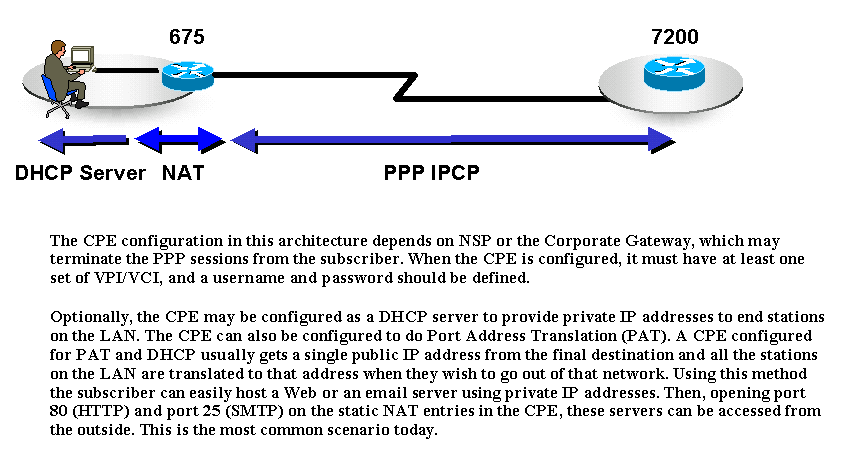
Due to the nature of PAT, certain applications that embed IP information in the payload cannot work in this scenario. To solve this issue, apply a subnet of IP addresses rather than a single IP address.
In this architecture it is easier for the NAP/NSP to Telnet into the CPE to configure and troubleshoot since an IP address is assigned to the CPE.
CPEs can use different options depending on the subscriber?s profile. For example, for a residential user the CPE may be configured without PAT/DHCP. For subscribers with more than one PC, CPEs can be configured either for PAT/DHCP or the same way as that of a residential user. If there is an IP phone connected to the CPE, the CPE may be configured for more than one PVC.
IP Management
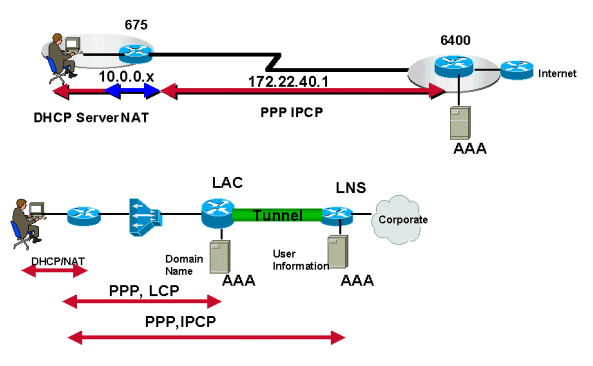
In PPPoA architecture, IP address allocation for the subscriber CPE uses IPCP negotiation, the same principle of PPP in dial mode. IP addresses are allocated depending on the type of service a subscriber uses. If the subscriber has only Internet access from the NSP, the NSP will terminate those PPP sessions from the subscriber and will assign an IP address. The IP address is allocated from a locally defined pool, a DHCP server, or can be applied from the RADIUS server. Also, the ISP may have provided a set of static IP addresses to the subscriber and may not assign IP addresses dynamically when the subscriber initiates the PPP session. In this scenario, the service provider will use only the RADIUS server to authenticate the user.
If the subscriber prefers to have multiple services available, the NSP may need to implement SSG. Following are possibilities for assigning IP addresses.
-
The SP may provide an IP address to the subscriber through its local pool or RADIUS server. After the user selects a service, the SSG forwards the user?s traffic to that destination. If the SSG is using proxy mode, the final destination may provide an IP address, which the SSG will use as the visible address for NAT.
-
The PPP sessions do not get terminated on the service provider?s aggregation router. They are either tunneled or forwarded to the final destination or home gateway, which will eventually terminate the PPP sessions. The final destination or home gateway negotiates IPCP with the subscriber, thereby providing an IP address dynamically. Static addresses are also possible as long as the final destination has allocated those IP addresses and has a route to them.
Prior to Cisco IOS Software Release 12.0.5DC for the Cisco 6400 NRP, there was no way for the service provider to provide a subnet of IP addresses to the subscriber. The Cisco 6400 platform and Cisco 600 series CPEs allow IP subnets to be dynamically configured on the CPE during PPP negotiation. One IP address from this subnet is assigned to the CPE and the remaining IP addresses are dynamically allocated to the stations through DHCP. When this feature is used, CPEs do not need to be configured for PAT, which does not work with some applications.
How the Service Destination is Reached
In PPPoA architectures, the service destination can be reached in different ways. Some of the most commonly deployed methods are:
-
Terminating PPP sessions at the service provider
-
L2TP Tunneling
-
Using SSG
In all three methods there is a fixed set of PVCs defined from the CPE to the DSLAM that is switched to a fixed set of PVCs on the aggregation router. The PVCs are mapped from the DSLAM to the aggregation router through an ATM cloud.
The service destination can also be reached using other methods such PPPoA with SVCs, or Multiprotocol Label Switching/Virtual Private Network. These methods are beyond the scope of this document and will be discussed in separate papers.
Terminating PPP at Aggregation
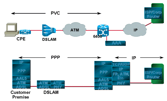
The PPP sessions initiated by the subscriber are terminated at the service provider which authenticates users using either a local database on the router or through RADIUS servers. After the user is authenticated, IPCP negotiation takes place and the IP address is assigned to the CPE. After the IP address has been assigned, there is a host route established both on the CPE and on the aggregation router. The IP addresses allocated to the subscriber, if legal, are advertised to the edge router. The edge router is the gateway through which the subscriber can access the Internet. If the IP addresses are private, the service provider translates them before advertising them to the edge router.
L2TP/L2F Tunneling
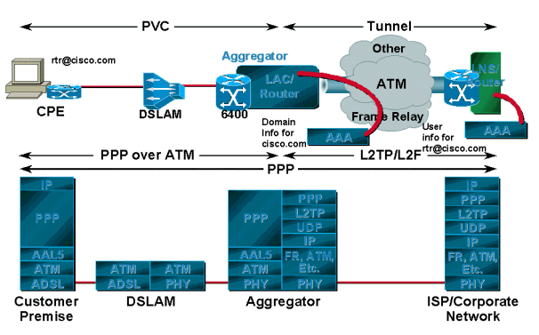
PPP sessions, depending on the service provider or corporation, tunnel to the upstream termination point using L2TP or L2F instead of being terminated on the service provider?s aggregation router. This termination point authenticates the username and the subscriber is assigned an IP address via DHCP or a local pool. For this scenario there is usually one tunnel established between the L2TP Access Concentrator/network access server (LAC/NAS) and home gateway or L2TP Network Server (LNS). The LAC authenticates the incoming session based on the domain name; the username is authenticated at the final destination or home gateway.
In this model, however, the user can only have access to the final destination and can access only one destination at a time. For example, if the CPE is configured with a username of rtr@cisco.com, the PCs behind that CPE can only have access to the Cisco domain. If they want to connect to another corporate network, they need to change the username and password on the CPE to reflect that corporate domain name. The tunnel destination in this case is reached by using a routing protocol, static routes, or doing classical IP over ATM (if the ATM is preferred as Layer 2).
Using Service Selection Gateway (SSG)
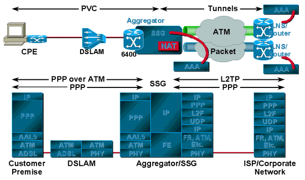
The main advantage of SSG over tunneling is that SSG provides mapping of one-to-many services, whereas tunneling provides only one-to-one mapping. This becomes very useful when a single user needs access to multiple services, or multiple users at a single location each need access to a unique service. SSG uses the Web-based Service Selection Dashboard (SSD), which consists of different services and is available to the user. The user can access one service or multiple services at one time. Another advantage of using SSG is that the service provider can bill the user based on the services used and the session time, and the user can turn services on and off through the SSD.
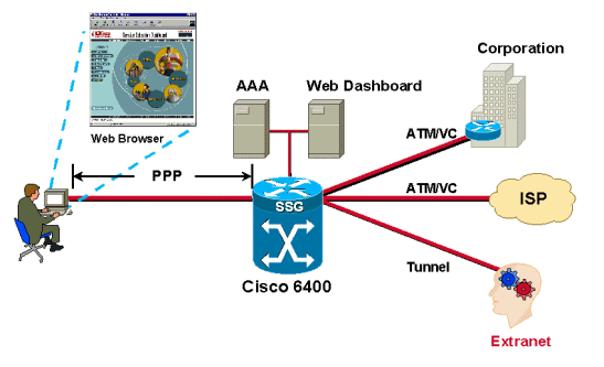
Users are authenticated as the PPP session comes in from the subscribers. Users are assigned IP addresses from either the local pool or the RADIUS server. After a user is successfully authenticated, a source object is created by the SSG code and the user is given access to a default network. The default network contains the SSD server. Using a browser, the user logs in to the Dashboard, is authenticated by the AAA server, and depending on the user?s profile stored in the RADIUS server, is offered a set of services to access.
Each time an authenticated user selects a service, the SSG creates a destination object for that user. The destination object contains information such as the destination address, the DNS server address for that destination, and the assigned source IP address from the home gateway. Packets coming in from the user?s side are forwarded to the destination based on the information contained in the destination object.
SSG can be configured for proxy service, transparent passthrough, or PTA. When a subscriber requests access to a proxy service, the NRP-SSG will pass the access-request to the remote RADIUS server. Upon receiving the access-accept, the SSG responds to the subscriber with the access-accept. The SSG appears as a client to the remote RADIUS server.
Transparent passthrough allows unauthenticated subscriber traffic to be routed through the SSG in either direction. Use filters to control transparent passthrough traffic.
PTA can only be used by PPP-type users. Authentication, Authorization and Accounting is performed exactly as in the proxy service type. A subscriber logs in to a service using a username of the form user@service. The SSG forwards that to the RADIUS server, which then loads the service profile to the SSG. The SSG forwards the request to the remote RADIUS server as specified by the service profile?s RADIUS server attribute. After the request is authenticated, an IP address is assigned to the subscriber. No NAT is performed. All user traffic is aggregated to the remote network. With PTA, users can access only one service and will not have access to the default network or the SSD.
Operational Description of PPPoA Architecture
When the CPE is first powered on, it starts sending LCP configuration requests to the aggregation server. The aggregation server, with the PVCs configured, also sends out the LCP configuration request on a Virtual Access Interface (associated with the PVC). When each one sees the configuration request of the other, they acknowledge the requests and the LCP state is opened.
For the authentication stage, the CPE sends the authentication request to the aggregation server. The server, depending on its configuration, either authenticates the user based on the domain name (if supplied), or the username using its local database or RADIUS servers. If the request from the subscriber is in the form of username@domainname, the aggregation server will try to create a tunnel to the destination, if one is not already there. After the tunnel is created, the aggregation server forwards the PPP requests from the subscriber to the destination. The destination, in turn, authenticates the user and assigns an IP address. If the request from the subscriber does not include the domain name, the user is authenticated by the local database. If SSG is configured on the aggregation router, the user can access the default network as specified and can get an option to select different services.
Conclusion
PPPoA is becoming the most suitable architecture for many service providers because it is highly scalable, uses SSG functionality, and provides security. Since the focus of this paper was PPPoA architecture, it was not possible to cover features like SSG in depth. These features will be covered in subsequent papers. Sample configurations for the different scenarios discussed in this document will also be presented and explained in separate papers.
 Feedback