Configuring Clock Settings on POS Router Interfaces
Available Languages
Contents
Introduction
This document reviews the recommended clock source settings for packet over SONET (POS) router interfaces connected over dark fiber, back-to-back, or across a telephone company (Telco) network.
Select the best clock settings to ensure accurate data recovery and to avoid SONET-layer errors.
Prerequisites
Requirements
There are no specific requirements for this document.
Components Used
This document is not restricted to specific software and hardware versions.
Conventions
Refer to Cisco Technical Tips Conventions for more information on document conventions.
Recommended Clock Settings for Router POS Interfaces
This table summarizes the recommended clock settings for router POS interfaces:
| Clock Source at Both Ends of the POS Link | Back to Back with Dark Fiber or DWDM | Telco Network with ADM or MUX |
|---|---|---|
| internal - internal | Yes | No |
| internal - line | Yes | No |
| line - internal | Yes | No |
| line - line | No | Yes |
The rest of this document discusses the reasons for these recommended settings.
Configuration 1: Back to Back, Dark Fiber, or DWDM
Cisco recommends that you configure internal-to-internal or line-to-internal in this configuration. Do not set both sides to derive clocking from the line in this configuration in order to avoid frequency drifts and line interruptions, including intermittent errors and even link failures.
In order to configure two routers for a back-to-back connection, use the clock source internal command.
| RouterA |
|---|
interface POS0/0 ip address 5.0.2.1 255.255.255.0 clock source internal |
| RouterB |
|---|
interface POS1/0 ip address 5.0.2.2 255.255.255.0 clock source internal |
Why Internal-to-Internal?
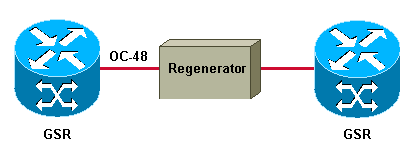
This section explains the importance of internal-to-internal for a back-to-back or dark fiber configuration. Figure 1 illustrates a back-to-back topology.
Figure 1 – Back-to-back Topology 
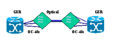
Figure 2 illustrates a POS connection over dark fiber.
Figure 2 – POS Connection Over Dark Fiber 
A common misconception about clocking is that both ends of any synchronous link must use the same clock, so one end must derive clocking from the line. This statement is true for DCE-to-DTE connections. However, this statement is not true for bidirectional layer-1 links, such as SONET.
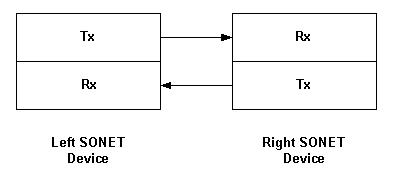
Here is an example to explain why this statement does not hold good for bidirectional layer-1 links:
Figure 3 – Bidirectional Layer-1 Link 
Here, each one-way link is synchronized.
-
The right SONET receiver (Rx) is synchronous with the left SONET transmitter (Tx).
-
The left SONET receiver is synchronous with the right SONET transmitter.
However, both one-way links do not have to be synchronized together. In other words, the link from left to right does not need to be synchronous with the link from right to left.
Consider that a POS interface consists of two physical strands of fiber. Each strand provides a one-way link.
Importantly, with clock source internal, the router performs these actions:
-
The transmitter uses the internal clock to time the transmit signal.
-
The receiver always uses the clock recovered from the receive line to synchronize with the transmitter at the remote end.
Therefore, you can configure internal clocking on both router ends. The clock source command determines the source of the transmit clock only.
A packet-based application of SONET – and any SONET-based point-to-point configuration – supports internal-internal clock settings with either Stratum 3 or Stratum 4 oscillators. Clocks must comply with the SONET Minimum Clock (SMC) specification, which defines 20 parts per million (ppm) accuracy. The original SONET networks, which supported point-to-point OC-48 links that typically carried DS-3 frames, and the pre-SONET Plesiochronous Digital Hierarchy (PDH) networks also were timed with 20ppm clocks. These early SONET systems are a direct analogy to POS links of today, which define a point-to-point connection between two routers with asynchronous interfaces to the rest of the network.
Point-to-point means that the SONET payload terminates at each POS interface. The router then extracts IP packets from within the PPP-encapsulated frame and forwards the packets to an output interface as though any non-POS interface, such as a serial or Ethernet interface receives the packets. This means that you can time each POS link independently, and you do not need to have all the POS interfaces on a router synchronized to a common clock.
POS mapping uses HDLC-like framing, and fills the gaps between consecutive packets with idle flags. That way, the IP payload rate is de-coupled from the SONET frame rate. The mapping does not require an extremely accurate clock to generate the outgoing SONET frame rate, and a 20ppm clock accuracy is more than sufficient. The huge buffers that the receiving interfaces use minimizes the impact of any excessive jitter.
Multi-node SONET networks can also transport payloads reliably with internal clocking configured at every node when the clocks are at least Stratum-3 accurate. However, Cisco does not recommend such configuration. Stratum 4 accurate clocks can result in a high rate of pointer justifications, which may lead to exceeding the jitter tolerance of the serviced asynchronous devices.
In summary, consider these points when you select a clock setting for back-to-back or dark fiber POS links:
-
POS defines a point-to-point technology. The SONET link terminates completely on the line card. No SONET information is passed between ports in a router. In contrast, a SONET add-drop multiplexer (ADM) typically passes the synchronous payload envelope (SPE) from ingress to egress port and modifies the pointer bytes to accommodate any timing offset between the two ports.
-
POS uses an asynchronous mapping. The SONET frame determines the rate at which packets are "stuffed" into SONET frames byte-by-byte. On the transmit side, a router POS interface sets the H1/H2 pointer bytes to a fixed value of 522. This value is chosen because the pointer value positions the SPE at the beginning of the frame that follows the pointers. Framer designers have to pick some arbitrary value to use, so they tend to pick "nice" values, like 522. In a dark fiber or DWDM configuration, the path does not include any equipment that alters or processes the pointer bytes, so the SONET frame arrives at the receiver with the same fixed value of 522 for the H1/H2 bytes. Thus, there is no possibility of clocking slips or SPE slips.
When to Choose Line-to-Internal
Alternately, you can configure one end of the link for clock source line. Importantly, the result of this configuration is that the transmitter now uses the clock recovered from the line by the local receiver, to time the transmitted signal.
Configure clock source line on one end (and only one end) of your POS link when the derived clock source is of higher quality than the clock available on the router POS interface. Engine 3 and Engine 4 line cards of the Cisco 12000 Series use a Stratum 3 clock source. All Engine 0 - 2 line cards other than the 1xOC48 SRP line card (OC48/SRP-SR-SC-B) use an SMC source. A byproduct of a line-internal configuration is that both directions of the link use the same clock, but this does not need to be the reason.
The disadvantage of line-internal is that a clock hit in one direction causes the interface trying to time itself from the line to send errors out because it is now using a "bad" signal as its source. Internal-internal separates the two clocking domains. An error on one side does not cause an error on the other. Clocking internal on both sides ensures that an error in the received clock (on loop side) does not affect Tx traffic.
The discussion so far illustrates that the clock source line configuration on both ends of a POS link is inherently unstable. With line-to-line, both transmitters use the clock received from the remote end, and neither end actually supplies the clock. This incorrect configuration leads to a timing loop.
Note: A limited batch of 1xOC12 POS line cards for the GSR experienced timing-related errors due to a problem with the onboard oscillator. The oscillator required the incoming and outgoing clocks to be identical. Therefore, appropriate line-internal clock setting configurations resolved most timing-related errors. This problem does not affect any other POS line cards.
Configuration 2: Connect Across a SONET Cloud
With this configuration, Cisco recommends that you configure both sides to derive clocking from the line. Cisco router POS interfaces use line clocking by default. Configure clock source line if you previously changed the clock setting.
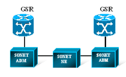
Figure 4 illustrates a POS connection over a SONET network.
Figure 4 – POS Connection Over a SONET Network 
Typically, the SONET cloud provides a more accurate or higher Stratum level clock source than router hardware. In rare circumstances, a POS interface increments the PSE / NSE counters and reports pointer adjustments with line-line clocking. Such pointer adjustments indicate a problem with timing or clock drift in the provider network. Report any such problems to the provider.
Related Information
Revision History
| Revision | Publish Date | Comments |
|---|---|---|
1.0 |
05-Sep-2006 |
Initial Release |
Contact Cisco
- Open a Support Case

- (Requires a Cisco Service Contract)
 Feedback