Inspection and Cleaning Procedures for Fiber-Optic Connections
Available Languages
Bias-Free Language
The documentation set for this product strives to use bias-free language. For the purposes of this documentation set, bias-free is defined as language that does not imply discrimination based on age, disability, gender, racial identity, ethnic identity, sexual orientation, socioeconomic status, and intersectionality. Exceptions may be present in the documentation due to language that is hardcoded in the user interfaces of the product software, language used based on RFP documentation, or language that is used by a referenced third-party product. Learn more about how Cisco is using Inclusive Language.
Contents
Introduction
This document describes inspection and cleaning processes for fiber optic connections. It is important that every fiber connector be inspected and cleaned prior to mating.
The procedures in this document describe basic inspection techniques and processes of cleaning for fiber optic cables, bulkheads, and adapters used in fiber optic connections.
Note: This document is intended for use by service personnel, field service technicians, and hardware installers.
Inspection and Cleaning are Critical
Clean fiber optic components are a requirement for quality connections between fiber optic equipment. One of the most basic and important procedures for the maintenance of fiber optic systems is to clean the fiber optic equipment.
Any contamination in the fiber connection can cause failure of the component or failure of the whole system. Even microscopic dust particles can cause a variety of problems for optical connections. A particle that partially or completely blocks the core generates strong back reflections, which can cause instability in the laser system. Dust particles trapped between two fiber faces can scratch the glass surfaces. Even if a particle is only situated on the cladding or the edge of the endface, it can cause an air gap or misalignment between the fiber cores which significantly degrades the optical signal.
-
A 1-micrometer dust particle on a single-mode core can block up to 1% of the light (a 0.05dB loss).
-
A 9-micrometer speck is still too small to see without a microscope, but it can completely block the fiber core. These contaminants can be more difficult to remove than dust particles.
By comparison, a typical human hair is 50 to 75 micrometers in diameter, as much as eight times larger. So, even though dust might not be visible, it is still present in the air and can deposit onto the connector. In addition to dust, other types of contamination must also be cleaned off the endface. Such materials include:
-
Oils, frequently from human hands
-
Film residues, condensed from vapors in the air
-
Powdery coatings, left after water or other solvents evaporate away
These contaminants can be more difficult to remove than dust particles and can also cause damage to equipment if not removed.
Caution: With the high powered lasers now in use for communications systems, any contaminant can be burned into the fiber endface if it blocks the core while the laser is turned on. This burn might damage the optical surface enough that it cannot be cleaned.
When you clean fiber components, always complete the steps in the procedures carefully. The goal is to eliminate any dust or contamination and to provide a clean environment for the fiber-optic connection. Remember that inspection, cleaning and re-inspection are critical steps which must be done before you make any fiber-optic connection.
General Reminders and Warnings
Review these reminders and warnings before you inspect and clean your fiber-optic connections.
Reminders
-
Always turn off any laser sources before you inspect fiber connectors, optical components, or bulkheads.
-
Always make sure that the cable is disconnected at both ends or that the card or pluggable receiver is removed from the chassis.
-
Always wear the appropriate safety glasses when required in your area. Be sure that any laser safety glasses meet federal and state regulations and are matched to the lasers used within your environment.
-
Always inspect the connectors or adapters before you clean.
-
Always inspect and clean the connectors before you make a connection.
-
Always use the connector housing to plug or unplug a fiber.
-
Always keep a protective cap on unplugged fiber connectors.
-
Always store unused protective caps in a resealable container in order to prevent the possibility of the transfer of dust to the fiber. Locate the containers near the connectors for easy access.
-
Always discard used tissues and swabs properly.
Warnings
-
Never use alcohol or wet cleaning without a way to ensure that it does not leave residue on the endface. It can cause damage to the equipment.
-
Never look into a fiber while the system lasers are on.
-
Never clean bulkheads or receptacle devices without a way to inspect them.
-
Never touch products without being properly grounded.
-
Never use unfiltered handheld magnifiers or focusing optics to inspect fiber connectors.
-
Never connect a fiber to a fiberscope while the system lasers are on.
-
Never touch the end face of the fiber connectors.
-
Never twist or pull forcefully on the fiber cable.
-
Never reuse any tissue, swab, or cleaning cassette reel.
-
Never touch the clean area of a tissue, swab, or cleaning fabric.
-
Never touch any portion of a tissue or swab where alcohol was applied.
-
Never touch the dispensing tip of an alcohol bottle.
-
Never use alcohol around an open flame or spark; alcohol is very flammable.
Best Practices
-
Resealable containers should be used to store all cleaning tools, and store endcaps in a separate container. The inside of these containers must be kept very clean and the lid should be kept tightly closed in order to avoid contamination of the contents during fiber connection.
-
Never allow cleaning alcohol to evaporate slowly off the ferrule as it can leave residual material on the cladding and fiber core. This is extremely difficult to clean off without another wet cleaning and usually more difficult to remove than the original contaminant. Liquid alcohol can also remain in small crevices or cavities where it might re-emerge.
General Inspection and Cleaning Procedures
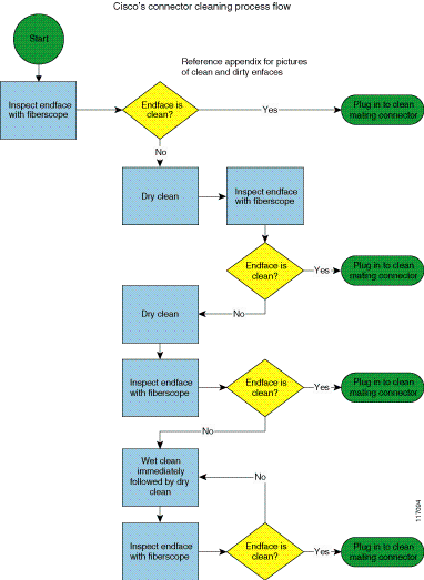
This section describes the connector cleaning process. Additional sections provide more detail on specific inspection and cleaning techniques.
General Cleaning Process
Complete these steps:
-
Inspect the fiber connector, component, or bulkhead with a fiberscope.
-
If the connector is dirty, clean it with a dry cleaning technique.
-
Inspect the connector.
-
If the connector is still dirty, repeat the dry cleaning technique.
-
Inspect the connector.
-
If the connector is still dirty, clean it with a wet cleaning technique followed immediately with a dry clean in order to ensure no residue is left on the endface.
Note: Wet cleaning is not recommended for bulkheads and receptacles. Damage to equipment can occur.
-
Inspect the connector again.
-
If the contaminate still cannot be removed, repeat the cleaning procedure until the endface is clean.
Figure 1 shows the connector cleaning process flow.
Figure 1
Note: Never use alcohol or wet cleaning without a way to ensure that it does not leave residue on the endface. It can cause equipment damage.
Connector Inspection Technique
This inspection technique is done with the use of fiberscopes in order to view the endface.
A fiberscope is a customized microscope used in order to inspect optical fiber components. The fiberscope should provide at least 200x total magnification. Specific adapters are needed to properly inspect the endface of most connector types, for example: 1.25 mm, 2.5 mm, or APC connectors.
Tools
-
Clean, resealable container for the endcaps
-
Fiberscope
-
Bulkhead probe
Figure 2 shows different kinds of fiberscopes.
Figure 2
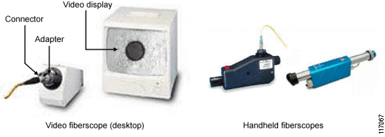
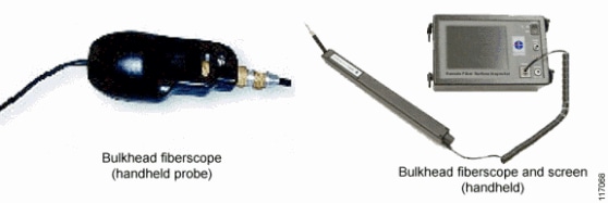
The bulkhead probe is a handheld fiberscope used in order to inspect connectors in a bulkhead, backplane, or receptacle port. It should provide at least 200x total magnification displayed on a video monitor. Handheld portable monitors are also available. Specific adapters are needed in order to properly inspect the endface of most connector types.
Figure 3 shows a handheld fiberscope with probe and adapter tip for 1.25 mm connector.
Figure 3
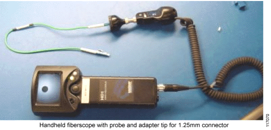
Figure 4 shows two types of handheld fiberscopes.
Figure 4
Caution: Read the reminders and warnings before you begin this process.
Complete these steps in order to inspect the connector:
-
Make sure that the lasers are turned off before you begin the inspection.
Warning: Invisible laser radiation might be emitted from disconnected fibers or connectors. Do not stare into beams or view directly with optical instruments.
-
Remove the protective cap and store it in a clean resealable container.
-
Verify the style of connector you inspect and put the appropriate inspection adapter or probe on your equipment.
-
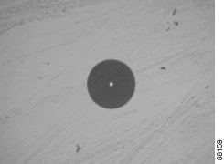
Insert the fiber connector into the fiberscope adapter, and adjust the focus ring so that you see a clear endface image. Figure 5 shows a clean single mode connector endface.
Figure 5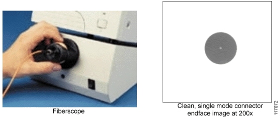
-
Or, place the tip of the handheld probe into the bulkhead connector and adjust the focus.
Figure 6 shows the handheld probe inserted into a bulkhead connection.
Figure 6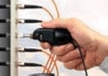
-
On the video monitor, verify that there is no contamination present on the connector endface.
Tip: See the examples in Appendix B - Sample Images of Contamination Conditions for illustrations of different types of contamination.
-
Clean the endface and reinspect, as necessary. Refer to the appropriate section:
-
Immediately plug the clean connector into the mating clean connector in order to reduce the risk of recontamination.
Cleaning Techniques for Pigtails and Patch Cords
This section describes cleaning techniques for pigtails and patchcords.
Note: No known cleaning methods are 100% effective; therefore, it is imperative that inspection is included as part of the cleaning process. Improper cleaning can cause damage to the equipment.
Dry Cleaning Technique: Cartridge and Pocket Style Cleaners
This section describes dry cleaning techniques with the use of cartridge and pocket style cleaners.
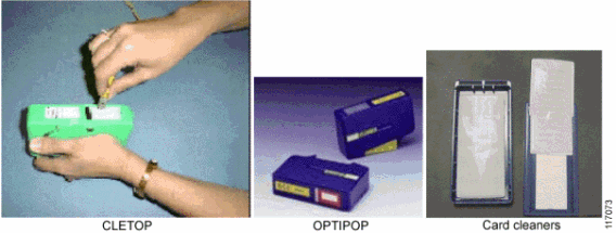
Tools
-
Cartridge Cleaning Tools: OPTIPOP and CLETOP
-
Pocket Style Cleaning Tools: CARDCLEANER
Figure7
Caution: Read the reminders and warnings before you begin this process.
-
Make sure that the lasers are turned off before you begin the inspection.
Warning: Invisible laser radiation might be emitted from disconnected fibers or connectors. Do not stare into beams or view directly with optical instruments.
-
Remove the protective endcap and store it in a small resealable container.
-
Inspect the connector with a fiberscope. See the Connector Inspection Technique section.
-
If the connector is dirty, clean with a cartridge or pocket cleaner.
-
For cartridge cleaners, press down and hold the thumb lever. The shutter slides back and exposes a new cleaning area, then go to step 5.
-
For pocket cleaners, peel back protective film for one cleaning surface, and then go to step 5.
-
For manual advance cleaners, pull on the cleaning material from the bottom of the device until a new strip appears in the cleaning window, and then go to step 5.
-
-
Hold the fiber tip lightly against the cleaning area.
-
For single, non-APC fiber connectors, rotate the fiber once through a quarter turn, 90 degrees.
-
For APC connector endfaces, hold cleaning area at the same angle as the endface.
-
-
Pull the fiber tip lightly down the exposed cleaning area in the direction of the arrow or from top to bottom.
Caution: Do not scrub the fiber against the fabric or clean over the same surface more than once. This can potentially contaminate or damage your connector.
-
For pocket style cleaners, go to step 8.
-
For single fiber connectors with the type A CLETOP, repeat the cleaning process in the second clean slot (step 5 and step 6).
-
-
Release the thumb lever to close the cleaning window, if you use cartridge type cleaners.
-
Inspect the connector again with the fiberscope. Refer to the Connector Inspection Technique section.
-
Repeat the inspection and cleaning processes, as necessary.
Caution: Throw away any used cleaning material, either cards or material cartridges, after use.
Dry Clean Technique: Lint-Free Wipes
This section describes dry cleaning techniques that use lint-free wipes.
Tools
-
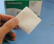
Lint-free wipes, preferably clean room quality
Figure 8
Caution: Read the reminders and warnings before you begin this process.
-
Make sure that the lasers are turned off before you begin the inspection.
Warning: Invisible laser radiation might be emitted from disconnected fibers or connectors. Do not stare into beams or view directly with optical instruments.
-
Remove the protective endcap and store it in a small resealable container.
-
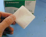
Fold the wipe into a square about 4 to 8 layers thick, see Figure 8.
-
Inspect the connector with a fiberscope. Refer to the Connector Inspection Technique section.
If the connector is dirty, clean it with a lint-free wipe.
Caution: Be careful not to contaminate the cleaning area of the wipe with your hands or on a surface during folding.
-
Lightly wipe the ferrule tip in the central portion of the wipe with a figure 8 motion.
Caution: Do not scrub the fiber against the wipe. If you do it, it can cause scratches and more contamination.
-
Repeat the Figure 8 wiping action on another clean section of the wipe.
-
Properly dispose of the wipe.
-
Inspect the connector again with the fiberscope.
-
Repeat this process as necessary.
Dry Clean: Lint-Free Swabs
This section describes dry cleaning techniques that uses lint-free swabs.
Tools
-
Lint-free swabs, preferably clean room quality
Figure 9

Caution: Read the reminders and warnings before you begin this process.
-
Make sure that the lasers are turned off before you begin the inspection.
Warning: Invisible laser radiation might be emitted from disconnected fibers or connectors. Do not stare into beams or view directly with optical instruments.
-
Remove the protective endcap and store it in a small resealable container.
-
Inspect the connector with a fiberscope. Refer to the Connector Inspection Technique section.
-
If the connector is dirty, clean it with a lint-free swab.
Figure 10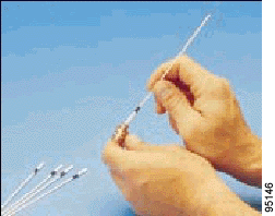
-
Lightly press and turn the swab to clean the ferrule face.
-
Properly dispose of the swab. Never reuse a swab.
-
Inspect the connector again with the fiberscope.
-
Repeat this process as necessary.
Wet Cleaning Technique: Lint-Free Wipes
If a dry cleaning procedure does not remove the dirt from the fiber endface, then try the wet cleaning method.
Caution: Improper cleaning can cause damage to the equipment. The primary concern with the use of isopropyl alcohol is that it can be removed completely from the connector or adapter. Residual liquid alcohol acts as a transport mechanism for loose dirt on the endface. If the alcohol is allowed to evaporate slowly off the ferrule, it can leave residual material on the cladding and fiber core. This is extremely difficult to clean off without another wet cleaning and usually more difficult to remove than the original contaminant. Liquid alcohol can also remain in small crevices or cavities where it can re-emerge during fiber connection.
Tools
-
99% isopropyl alcohol
-
Lint-free wipes
Caution: On female multifiber connectors, ensure that no alcohol gets into the guide pin holes. The alcohol might come out during mating and contaminate your connection.
Caution: Do not use wet cleaning on E-2000 or F-3000 connectors because the connector can trap the alcohol and recontaminate the connector.
Caution: Read the reminders and warnings before you begin this process.
-
Make sure that the lasers are turned off before you begin the inspection.
Warning: Invisible laser radiation might be emitted from disconnected fibers or connectors. Do not stare into beams or view directly with optical instruments.
-
Remove the protective endcap and store it in a small resealable container.
-
Inspect the connector with a fiberscope. Refer to the Connector Inspection Technique section.
-
Fold the wipe into a square, about 4 to 8 layers thick. See Figure 11.
-
Moisten one section of the wipe with one drop of 99% alcohol. Be sure that a portion of the wipe remains dry.
-
Lightly wipe the ferrule tip in the alcohol moistened portion of the wipe with a figure 8 motion. Immediately repeat the figure 8 wiping action on the dry section of wipe to remove any residual alcohol. (See Caution).
Caution: Do not scrub the fiber against the wipe, doing so can cause scratches.
-
Properly dispose of the wipe. Never reuse a wipe.
-
Inspect the connector again with a fiberscope.
-
Repeat the process as necessary.
Cleaning Techniques for Bulkheads and Receptacles
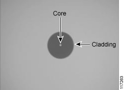
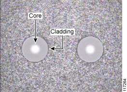
Receptacles refer to packaged devices with optical ports. Many receptacle devices use lens based systems which are less sensitive to contamination as opposed to fiber, but can be damaged if cleaned improperly. If you inspect a receptacle device and are not able to focus on the endface cladding, then you have a lensed device and should not attempt to clean it. See Figure 14 and Figure 15 for sample images of the endface core and cladding.
Cisco has found that the use of swabs for cleaning is not always very effective even for experienced operators. It might be better to leave an optical port alone unless signal effecting contamination is observed blocking the core. Contaminants can be pushed onto the endface in the process of the insertion of the swab.
Caution: Wet cleaning is not recommended for bulkheads and receptacles. Damage to equipment can occur.
Always make sure you plug in a clean mating connector in order to avoid cross contaminating the receptacle side. Ground in contamination is much harder to remove than loose debris.
Remember, inspect first and clean only if necessary!
Dry Clean: Lint-Free Swabs
This section describes dry cleaning techniques that uses lint-free swabs.
Tools
-
Lint-free swabs
Figure 12

Caution: Never clean bulkheads or receptacles without a way to inspect them afterwards. Cleaning can actually leave the endface in a worse condition.
Caution: Read the reminders and warnings before you begin this process.
-
Make sure that the lasers are turned off before you begin the inspection.
Warning: Invisible laser radiation might be emitted from disconnected fibers or connectors. Do not stare into beams or view directly with optical instruments.
-
Remove the protective endcap and store it in a small resealable container.
-
Inspect the fiber connector in the adapter or bulkhead with a fiberscope probe. Refer to the Connector Inspection Technique section.
-
If the adapter is dirty, select the appropriate lint-free swab according to the connector ferrule size.
-
Inspect the connector in the adapter again with a fiberscope probe.
-
Insert the clean lint-free swab into the adapter. See Figure 13.
Figure 13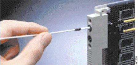
-
Turn the swab several complete revolutions in the same direction.
-
Properly dispose of the swab. Never reuse a swab.
-
Repeat the cleaning process as necessary.
Wet Clean: Lint-Free Swab
Caution: Improper cleaning can cause damage to equipment. The primary concern with the use of isopropyl alcohol is that it can be removed completely from the connector or adapter. Residual liquid alcohol acts as a transport mechanism for loose dirt on the endface. If the alcohol is allowed to evaporate slowly off the ferrule, it can leave residual material on the cladding and fiber core. This is extremely difficult to clean off without another wet cleaning and usually more difficult to remove than the original contaminant. Liquid alcohol can also remain in small crevices or cavities where it can re-emerge during fiber connection.
Caution: On female multifiber connectors, ensure no alcohol gets into the guide pin holes or it can come out during mating and contaminate your connection.
Tools
-
99% isopropyl alcohol
-
Lint-free swabs
Caution: Never clean bulkheads or receptacles without a way to inspect them afterwards. Cleaning can actually leave the endface in a worse condition as alcohol residue is one of the most difficult contaminants to remove.
-
Make sure that the lasers are turned off before you begin the inspection.
Warning:Invisible laser radiation might be emitted from disconnected fibers or connectors. Do not stare into beams or view directly with optical instruments.
-
Remove the protective endcap and store it in a small resealable container.
-
Inspect the connector with a fiberscope. Refer to the Connector Inspection Technique section.
-
If the dry cleaning procedure did not remove the dirt from the fiber endface, then place one drop of 99% alcohol to lightly moisten a new lint-free swab. Do not oversaturate the swab.
Tip: Have a dry lint-free swab available for drying immediately after the cleaning. Make sure that the drying swab stays clean. See Caution.
-
Lightly press and turn the dampened swab to clean the ferrule face.
-
Immediately after you clean, lightly press and turn the second swab (dry) to dry any alcohol that remains from the ferrule face.
-
Properly dispose of the wet and dry swab. Never reuse a swab.
-
Inspect the connector again.
Vendor-Specific Cleaning Techniques
Due to the proprietary nature of many cleaning techniques and the wide distribution of this document, only the part and document number and application is listed. The supplier should be contacted for detailed information.
3M OGI Bulkhead Cleaning Technique (Dry and Wet)
See Tools for contact information.
Tools
3M OGI Bulkhead Cleaning Kit (ref. 3M part # FCCS-1020)
Refer to 3M Worldwide for more information.
Appendix A - Connector Type—Inspection and Cleaning Cross Reference Chart
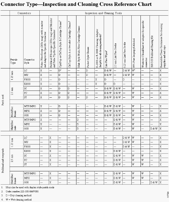
Appendix B - Sample Images of Contamination Conditions
These images describe various contamination conditions.
| Illustration | Description |
|---|---|
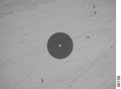
| Figure 14: A Clean Connector
|
Figure 14 shows a clean single mode ceramic endface at 200x magnification. Note: Sometimes the core is not illuminated. |
| Figure 15: Clean Multifiber Connector with Acceptable Shadowing
|
Figure 15 shows a clean multimode MT connector. Notice that there is a small amount of acceptable shadowing along the edge of the cladding. Note: There is more than one fiber visible at 200x magnification and sometimes the core is not illuminated. |
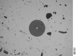
| Figure 16: Connector with Dust
|
Figure 16 shows a connector with dust particles spread across the surface of the endface that needs cleaning. |
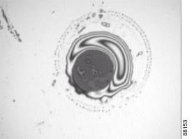
| Figure 17: Connector with Liquid Contamination
|
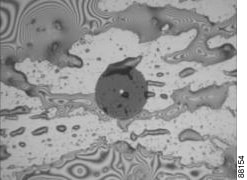
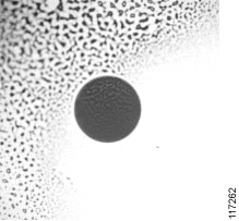
Figure 17 shows a connector with liquid contamination that needs cleaning. |
| Figure 18: Connector with Liquid Contamination
|
Figure 18 shows a connector with liquid contamination that needs cleaning. |
| Figure 19: Connector with Alcohol Residue Contamination
|
Figure 19 shows a connector with alcohol residue that needs cleaning. |
| Figure 20: Connector with Liquid Contamination
|
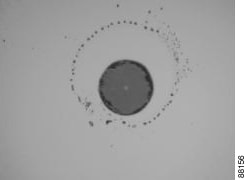
Figure 20 shows a connector with small droplets of liquid contamination that needs cleaning. |
| Figure 21: Connector with Dry Residue
|
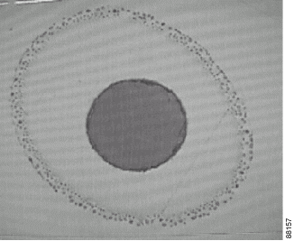
Figure 21 shows a connector with a dry residue that needs cleaning. |
| Figure 22: Connector with Oil Residue
|
Figure 22 shows a connector with an oil residue that needs cleaning. |
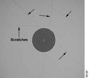
| Figure 23: Connector with Scratches
|
Figure 23 shows a connector with scratches. These scratches are not detrimental to the endface and does not clean off. But, deep scratches that appear to cross the fiber-optic core can cause signal loss. |
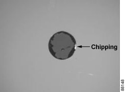
| Figure 24: Connector with Chipped Cladding and Excessive Epoxy
|
Figure 24 shows a connector with damage to the cladding. Cleaning cannot remove damaged cladding. A small amount of epoxy around the cladding is allowable, but this shows excessive epoxy around the cladding that does not clean off. This connector must be replaced. |
| Figure 25: Damaged Connector
|
Figure 25 shows a 1.25 mm ferrule that has been over chamfered. The connector must be replaced. |
Appendix C - Connector Definitions and Descriptions
| Connector Part or Type | Description |
|---|---|
| APC (Angled Physical Contact) | This is a fiber optic polishing style that has an 8 degree angle on the endface. This connector style is typically indicated by a green connector body or green strain relief boot. |
| Backplane Connector | This is a fiber optic connector that mates the rear of the PCA to the inside back wall of the chassis. |
| Bulkhead Adapter | This is a plastic or metal housing which allows two fiber-optic connectors to mate. Typically these are located on the front panel or the backplane of a PCA. |
| Connector | This is a plastic or metal housing located at the end of a fiber-optic cable to connect cables to a transmitter, receiver, or another cable. |
| Cladding | This is the inside region of the fiber optic endface that is made of a low refractive index glass. This region starts at the outside edge of the core and ends at a diameter of 125 microns. |
| Core | This is the center most region of the fiber optic endface that carries and guides the majority of the light. The diameter can be 9 microns, 50 microns, or 62.5 microns that depend on fiber type. Note: Often the core might not be illuminated and is indistinguishable from the cladding. |
| E2000 | This is a fiber optic connector style with a single-fiber 2.5 mm diameter ferrule. This specialized connector uses a metallic ferrule and has a spring-loaded protective shutter. It is offered exclusively by Diamond, Inc. See Figure 29. |
| Endface | This is the mating surface of a fiber optic connector. It consists of a glass core and cladding, surrounded by a ferrule made of either ceramic, plastic, or metal. It is critical to keep this entire area protected from damage at all times. |
| F3000 | This is a fiber optic connector style with a single-fiber 1.25 mm diameter ferrule. This specialized connector uses a metallic ferrule and has a spring-loaded protective shutter. It is offered exclusively by Diamond, Inc. and does not fit into all LC ports. |
| FC | A fiber optic connector style with a single-fiber 2.5 mm diameter ferrule. It features a keyed, threaded barrel that is used to mate the connector. See Figure 28. |
| Ferrule | The outside portion of the fiber optic endface that is precisely hollowed out to hold and align the glass cladding and core. It is typically made of an insulative material such as ceramic or plastic. They are available in single-fiber and multi-fiber styles. |
| LC | This is a fiber optic connector style with a single-fiber diameter ferrule. It features a distinctive plastic latch on the connector 1.25 mm body that provides a positive engagement when mated. See Figure 26. |
| MPO (also known as MTP) | This is a fiber optic connector style with a multi-fiber plastic ferrule. See Figure 31. |
| MU | This is a fiber optic connector style with a single-fiber 1.25 mm diameter ferrule. See Figure 30. |
| Multimode Fiber | This is an optical fiber which transmits or emits multiple modes of light. These fibers usually have a large core, typically 50 or 62.5 microns. |
| OGI | This is a fiber optic connector style with a multi-fiber plastic ferrule. It is offered exclusively by 3M, Inc. See Figure 32. |
| PC (Physical Contact) | This is a fiber optic polishing style that has a convex, domed endface. |
| Pigtailed Device | This is a packaged optical component with a length of fiber attached to a male connector. |
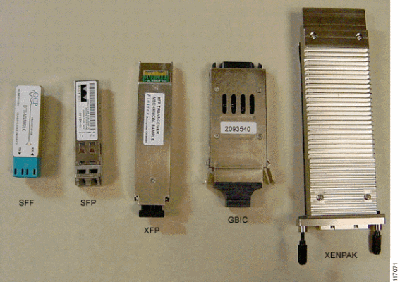
| Receptacle Device | This is a packaged optical component with female ports that typically mount flush to the front panel. These may use fiber or optical lenses internally, which depends on the design and/or vendor. SFPs, XFPs, GBICs, XenPAKs, & SFFs are all examples of receptacle transceiver devices. See Figure 33. |
| Ribbon Connector | This is another term for a multi-fiber connector. |
| SC | This is a fiber optic connector style with a single-fiber 2.5 mm diameter ferrule. See Figure 27. |
| Single Mode Fiber | This is an optical fiber that supports one spatial mode of light propagation. These fibers typically have a 9 micron core. |
| ST | This is a fiber optic connector style with a single-fiber 2.5 mm diameter ferrule. |
| UPC (Ultra-polished physical contact) | This is a fiber optic polishing style that has a convex, domed endface. It is highly polished to attain enhanced performance. |
Appendix D - Sample Connectors and Accessories
Note: Angled physical contact (APC) connectors typically have a green connector or boot. Blue and other color connectors have a flat or convex endface.
Figure 26: LC Type Connector and Accessories (1.25 mm ferrule)
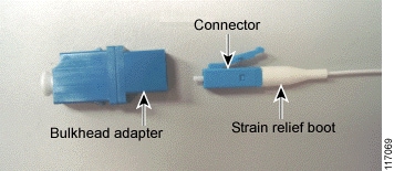
Figure 27: SC Type Connector and Accessories (2.5 mm ferrule)

Figure 28: FC Type Connector and Accessories (2.5 mm ferrule)
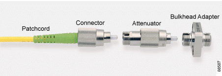
Figure 29: E2000 Type Connector and Accessories (2.5 mm ferrule)

Figure 30: MU Type Connector and Accessories (1.25 mm ferrule)
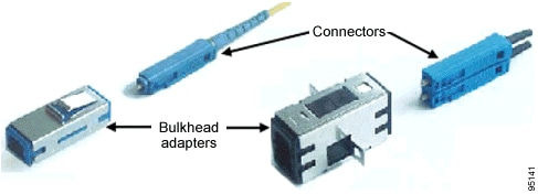
Figure 31: MTP/MPO Type Connector (multifiber ferrule)

Figure 32: OGI Type Connector (multifiber)

Figure 33: Receptacle Devices
Revision History
| Revision | Publish Date | Comments |
|---|---|---|
1.0 |
18-May-2004 |
Initial Release |
Contributed by Cisco Engineers
Contact Cisco
- Open a Support Case

- (Requires a Cisco Service Contract)
 Feedback