Measuring the Utilization of ATM PVCs
Available Languages
Contents
Introduction
Often is an important goal for network planners who need to determine if sufficient bandwidth was provisioned, as well as for service providers who need to provide accurate billing and accounting information to their customers, to be able to capture the utilization of an ATM permanent virtual circuit (PVC).
In general, ATM switches count in ATM cells, while ATM router interfaces count in frames or packets, specifically AAL5 PDUs (ATM adaptation layer 5 protocol data units). Thus, you cannot determine the utilization of a PVC on ATM router interfaces through a simple reading of a per-virtual circuit (VC) cell counter. Instead, you can measure per-VC utilization if you first collect packet and byte counts and then add the appropriate ATM overhead counts to produce a reasonable estimate.
Such calculations are the purpose of this document, which augments information already available in the Implementing Network Management on ATM Interfaces document.
Prerequisites
Requirements
There are no specific requirements for this document.
Components Used
This document is not restricted to specific software and hardware versions.
The information in this document was created from the devices in a specific lab environment. All of the devices used in this document started with a cleared (default) configuration. If your network is live, make sure that you understand the potential impact of any command.
Conventions
For more information on document conventions, refer to the Cisco Technical Tips Conventions.
Understand ATM Overhead
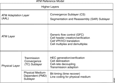
ATM is both a layer-2 protocol and a protocol stack, in a similar way that IP is a layer-3 protocol and a protocol stack. This diagram illustrates the ATM protocol stack:

All three layers introduce overhead. The next two sections discuss overhead added by the ATM layer and by the ATM adaptation layer. The physical-layer overhead is outside the scope of this document.
ATM Layer Overhead
The more well-understood ATM overhead is the so-called ATM cell tax or five-byte cell header. The format of this header is illustrated here:

AAL Layer Overhead
The ATM adaptation layer adds overhead that supports the quality of service needs of an ATM service category, like CBR or nrt-VBR. AAL5, which is the most commonly used AAL type. An AAL5 service data unit (SDU) is defined as the layer-three datagram plus the optional Logical Link Control/Subnetwork Access Protocol (LLC/SNAP) header. An AAL5 PDU is defined as the AAL5 SDU plus variable-length padding and the eight-byte AAL5 trailer. There are three pieces of overhead here:
-
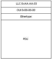
8-byte LLC/SNAP header (RFC 1483) in the format illustrated below. Note that a protocol ID value of 0800 indicates that AAL5 PDU is encapsulating an IP packet. Specify use of the LLC/SNAP header on ATM PVCs with the encapsulation aal5snap command, which is enabled by default.

-
Up to 47 octets of variable-length padding are used to make the AAL5 PDU an even multiple of 48 bytes. The feature module for Low Latency Queueing provides an interesting discussion of ATM overhead in the context of Voice over IP over ATM. It considers the example of a voice stream of 60-byte packets emitted at 50 packets per second. Before such packets are transmitted, the router adds an eight-byte LLC/SNAP header and then divides the now 68-byte packet into two 53-byte ATM cells. Thus, the bandwidth consumed by this flow is 106 bytes per packet.
-
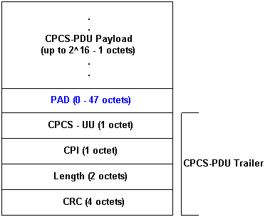
8-byte AAL5 trailer. RFC 1483 defines the format of an AAL5 trailer, as illustrated here:

Per-VC Statistics on Switches
Generally, ATM switches think in terms of ATM cells. You can obtain cell counts from either a Cisco IOS command or using Simple Network Management Protocol (SNMP) polling.
Use the switch show atm vc interface {atm} card/subcard/port [vpi vci] command to see per-VC cell counters at the command line, as shown here:
LightStream 1010#show atm vc interface atm 0/0/0 0 50
   Interface: ATM0/0/0, Type: oc3suni
     VPI = 0 VCI = 50
     Status: UP
     Time-since-last-status-change: 00:03:08
     Connection-type: PVC
     Cast-type: point-to-point
     Packet-discard-option: disabled
     Usage-Parameter-Control (UPC): pass
     Wrr weight: 2
     Number of OAM-configured connections: 0
     OAM-configuration: disabled
     OAM-states: Not-applicable
     Cross-connect-interface: ATM0/0/1, Type: oc3suni
     Cross-connect-VPI = 0
     Cross-connect-VCI = 55
     Cross-connect-UPC: pass
     Cross-connect OAM-configuration: disabled
     Cross-connect OAM-state: Not-applicable
     Threshold Group: 5, Cells queued: 0
     Rx cells: 0, Tx cells: 80
     Tx Clp0:80, Tx Clp1: 0
     Rx Clp0:0, Rx Clp1: 0
     Rx Upc Violations:0, Rx cell drops:0
     Rx Clp0 q full drops:0, Rx Clp1 qthresh drops:0
     Rx connection-traffic-table-index: 1
     Rx service-category: UBR (Unspecified Bit Rate)
     Rx pcr-clp01: 7113539
     Rx scr-clp01: none
     Rx mcr-clp01: none
     Rx cdvt: 1024 (from default for interface)
     Rx mbs: none
     Tx connection-traffic-table-index: 1
     Tx service-category: UBR (Unspecified Bit Rate)
     Tx pcr-clp01: 7113539
     Tx scr-clp01: none
     Tx mcr-clp01: none
     Tx cdvt: none
     Tx mbs: none
The output above shows that the VPI/VCI 0/50 has transmitted 80 cells.
Cisco campus ATM switches, such as the LightStream 1010 and Catalyst 8500 series, support the CISCO-ATM-CONN-MIB, which can be used to acquire per-VC cell counters using SNMP. This MIB is a Cisco extension to VPL/VCL tables defined in RFC 1695 ![]() , also known as the ATM-MIB, for ATM switch connection management. CISCO-ATM-CONN-MIB adds cell-specific, per-VC objects for management of the new features made possible on the LightStream 1010 and Catalyst 8500 by the Feature Card Plus:
, also known as the ATM-MIB, for ATM switch connection management. CISCO-ATM-CONN-MIB adds cell-specific, per-VC objects for management of the new features made possible on the LightStream 1010 and Catalyst 8500 by the Feature Card Plus:
-
Per-VC queuing hardware structures
-
Enhanced usage parameter control (UPC)
-
Per-connection snooping
-
Enhanced per-connection statistics
Note: CISCO-ATM-CONN-MIB is not available on routers with ATM interfaces.
Before discussing the cell counters in this MIB, it is important to understand the terminology used in the counters.
Virtual path links, labeled virtual path link (VPL) in the this diagram, are identified only by the virtual path identifier (VPI). VPLs are ATM connections that consist of multiple VCs with the same VPI number. They pass through ATM switches doing VP switching.

Virtual channel links, labeled VCL in this diagram, are identified by both the VPI and the virtual channel identifier (VCI). VCLs are the interconnections between switches, either directly or through VP tunnels.

The CISCO-ATM-CONN-MIB maintains VPL statistics in the ciscoAtmVplTable and VCL statistics in the ciscoAtmVclTable.
This table considers the value of the cell loss priority (CLP) bit in the counts. The CLP bit uses a value of zero to indicate higher priority and one to indicate lower priority of the cell when the ATM network experiences congestion. For every cell count, the switch considers the number of CLP=0 cells, the number of CLP=1 cells, and the number of CLP=0+1 cells.
| Object ID | Description |
|---|---|
| VPL Counters | |
| ciscoAtmVplInCells | Total number of cells received on this VPL. |
| ciscoAtmVplOutCells | Total number of cells transmitted on this VPL. |
| ciscoAtmVplInClp0Cells | Total number of cells with the CLP bit clear received on this VPL. Note that these cells may subsequently be discarded. This counter is valid only if the VPL is not a logical interface (tunnel) and only on LightStream 1010s equipped with a Feature Card - Per Flow Queueing. |
| ciscoAtmVplInClp1Cells | Total number of cells with the CLP bit set received on this VPL. Note that these cells may subsequently be discarded. This counter is valid only if the VPL is not a logical interface (tunnel) and only on LightStream 1010s equipped with a Feature Card - Per Flow Queueing. |
| ciscoAtmVplOutClp0Cells | Total number of cells with the CLP bit clear transmitted on this VPL. This counter is valid only if the VPL is not a logical interface (tunnel) and only on LightStream 1010s equipped with a Feature Card - Per Flow Queueing. |
| ciscoAtmVplOutClp1Cells | Total number of cells with the CLP bit set transmitted on this VPL. This counter is valid only if the VPL is not a logical interface (tunnel) and on LightStream 1010s equipped with a Feature Card - Per Flow Queueing. |
| VCL Counters | |
| ciscoAtmVclInCells | Total number of cells received on this VCL. |
| ciscoAtmVclOutCells | Total number of cells transmitted on this VCL. |
| ciscoAtmVclInClp0Cells | Total number of cells with the CLP bit clear received on this VCL. Note that these cells may subsequently be discarded. This counter is valid only on LightStream 1010s equipped with a Feature Card - Per Flow Queueing. |
| ciscoAtmVclInClp1Cells | Total number of cells with the CLP bit set received on this VCL. Note that these cells may subsequently be discarded. This counter is valid only on LightStream 1010s equipped with the Feature Card - Per Flow Queueing. |
| ciscoAtmVclOutClp0Cells | Total number of cells with the CLP bit clear transmitted on this VCL. This counter is valid only on LightStream 1010s equipped with a Feature Card - Per Flow Queueing. |
| ciscoAtmVclOutClp1Cells | Total number of cells with the CLP bit set transmitted on this VCL. This counter is valid only on LightStream 1010s equipped with a Feature Card - Per Flow Queueing. |
Per-VC Statistics on Routers
While ATM switches think in terms of cells, and do provide per-VC cell counts, routers with an ATM interface think in terms of packets (specifically, AAL5 PDUs). You can obtain correspondent counters from either a Cisco IOS command or using SNMP polling.
To capture per-VC counters using the command line, issue the show atm vc {vcd#} command as shown here:
7500#show atm vc 1
ATM1/0/0: VCD: 1, VPI: 0, VCI: 44
UBR, PeakRate: 155000
AAL5-LLC/SNAP, etype:0x0, Flags: 0xC20, VCmode: 0x0
OAM frequency: 0 second(s)
InARP frequency: 15 minutes(s)
InPkts: 2849714, OutPkts: 760158, InBytes: 1076168929, OutBytes:    33720309
InPRoc: 1532955, OutPRoc: 760122, Broadcasts: 0
InFast: 1316288, OutFast: 0, InAS: 694, OutAS: 40
Giants: 0
OAM cells received: 0
OAM cells sent: 0
Status: UP
In the output above, packets count the number of AAL5 PDUs. Note that bytes, counted for each AAL5 PDU in IOS, include only layer 3 packet bytes plus 8-byte LLC/SNAP header. These bytes do not include variable length padding, AAL5 trailer and ATM cell header. Counters, displayed by the show interface atm command for either a main ATM interface or an ATM subinterface have the same meaning.
SNMP access to the same per-VC counters, is possible using cAal5VccTable, which contains:
| Counter | Definition |
|---|---|
| cAal5VccInPkts | Number of AAL5 CPCS PDUs received on this AAL5 VCC at the interface associated with an AAL5 entity. |
| cAal5VccOutPkts | Number of AAL5 CPCS PDUs transmitted on this AAL5 VCC at the interface associated with an AAL5 entity. |
| cAal5VccInOctets | Number of AAL5 CPCS PDU octets received on this AAL5 VCC at the interface associated with an AAL5 entity. |
| cAal5VccOutOctets | Number of AAL5 CPCS PDU octets transmitted on this AAL5 VCC at the interface associated with an AAL5 entity. |
The table above is from CISCO-AAL5-MIB, which extends aal5VccTable defined in the ATM-MIB, adding per-circuit traffic counters (aal5VccTable itself contains only error counters). CISCO-AAL5-MIB supports ATM interfaces that act as endpoints of ATM connections and running Cisco IOS® software Release 11.2 F or 11.3 and above.
If your AAL5 VC is the only VC configured on a certain ATM subinterface, then you can get the same counters for it using SNMP using "aal5-layer" entries for that subinterface in the ifTable/ifXTable. For more information, refer to Implementing Network Management on ATM Interfaces.
Note: The peak cell rate and sustained cell rate values that you configure at the command line for ATM VCs on Cisco router interfaces take into account all overhead, including the 5-byte ATM cell header, AAL5 padding, and AAL5 trailer.
Calculate Per-VC and Per-Interface Kbps Rates
Use these steps to calculate utilization of your ATM VC:
-
Use a network management application to collect two readings for cAal5VccInOctets or cAal5VccOutOctets for the VC.
-
Calculate the delta between the two collections.
-
Add the number of octets that best estimates the AAL5 padding.
-
Add the eight-byte AAL5 trailer.
-
Convert the combined value to bits per seconds.
-
Multiply the values by 1.10 to account for 10 percent overhead of the five-byte ATM cell header.
To calculate interface or subinterface utilization, use a similar sequence of steps:
-
Use a network management application to poll two readings for ifInOctets counter or ifOutOctets (RFC 1213).
-
Calculate the delta between two collections of ifInOctets and ifOutOctets each.
-
Add the number of octets that best estimates the AAL5 padding.
-
Add the eight-byte AAL5 trailer.
-
Convert the combined value to bits per seconds.
-
Multiply the values by 1.10 to account for 10 percent overhead of the five-byte ATM cell header.
Note: Divide the above bps value by ifSpeed and then multiply the result by 100 to form a percentage.
Calculate ATM Overhead
ATM overhead can consume a significant part of a VC's bandwidth. The following shows how to estimate this value. First, consider that IP packets on the Internet typically are one of three sizes:
-
64 bytes (for example, control messages)
-
1500 bytes (for example, file transfers)
-
256 bytes (all other traffic)
These values produce a typical overall Internet packet size of 250 bytes. Next, consider that some overhead is predictable and some is variable.
| Overhead Field | Predictable | Variable |
|---|---|---|
| five-byte cell header (cell tax) | X | - |
| eight-byte AAL5 trailer | X | - |
| eight-byte LLC/SNAP header | X | - |
| Up to 47 bytes of AAL5 padding | - | X |
Now, use the above values to estimate the percentage of overhead on an ATM link based on the encapsulation type. In these calculations, assume a packet size of 250 bytes, which requires 22 bytes of padding after we include the eight-byte LLC/SNAPheader and eight-byte AAL5 trailer.
-
AAL5SNAP encapsulation:
8+8+22=38 or 15 percent "AAL5" overhead + 10 percent cell tax = >25 percent overall overhead
-
For AAL5MUX encapsulation, with 250 byte packets, 30 bytes of padding are required, which means:
8+30=38 or 15 percent "AAL5" overhead + 10 percent cell tax = >25 percent overall overhead
In other words, the overhead factor varies with packet size. Small packets result in higher padding, which results in increased overhead.
Cell Counters on Routers
Generally, routers only count AAL5 PDUs and not cells. There are some exceptions, however. Starting from 12.2(15)T, you can see cell counters on PA-A3 interfaces using command line interface show interface atm for subinterface or show atm vc {vcd#}, for example:
c7200#show int atm4/0.66
    ATM4/0.66 is up, line protocol is up
      Hardware is ENHANCED ATM PA
      Internet address is 10.10.10.1/24
      MTU 4470 bytes, BW 33920 Kbit, DLY 200 usec,
         reliability 255/255, txload 1/255, rxload 1/255
      Encapsulation ATM
      0 packets input, 0 cells, 0 bytes
      7 packets output, 16 cells, 572 bytes
      0 OAM cells input, 0 OAM cells output
      AAL5 CRC errors : 0
      AAL5 SAR Timeouts : 0
      AAL5 Oversized SDUs : 0
      Last clearing of "show interface" counters never
    c7200#show atm vc 4
    ATM4/0.66: VCD: 4, VPI: 0, VCI: 1000
    VBR-NRT, PeakRate: 1000, Average Rate: 1000, Burst Cells: 94
    AAL5-LLC/SNAP, etype:0x0, Flags: 0x20, VCmode: 0x0
    OAM frequency: 0 second(s)
    VC TxRingLimit: 40 particles
    VC Rx Limit: 18 particles
    InARP frequency: 15 minutes(s)
    Transmit priority 4
    InPkts: 0, OutPkts: 7, InBytes: 0, OutBytes: 572
    InCells: 0, OutCells: 16
    InPRoc: 0, OutPRoc: 7
    InFast: 0, OutFast: 0, InAS: 0, OutAS: 0
    InPktDrops: 0, OutPktDrops: 0/0/0 (holdq/outputq/total)
    InCellDrops: 0, OutCellDrops: 0
    InByteDrops: 0, OutByteDrops: 0
    CrcErrors: 0, SarTimeOuts: 0, OverSizedSDUs: 0, LengthViolation: 0, CPIErrors: 0
    Out CLP=1 Pkts: 0, Cells: 0
    OAM cells received: 0
    OAM cells sent: 0
    Status: UP
These counters were added as part of "Service Assurance Agent (SAA) for ATM" feature. Note that you can not access these cell counters using SNMP. Another exception is the inverse multiplexing over ATM (IMA) network module for the 2600 and 3600 series router. Issue the show controller atm command to view cell counts, as illustrated here:
3640-1.1#show controller atm 2/0
   Interface ATM2/0 is administratively down
    Hardware is ATM T1
   [output omitted]
   Link (0):DS1 MIB DATA:
    Data in current interval (419 seconds elapsed):
    0 Line Code Violations, 0 Path Code Violations
    0 Slip Secs, 0 Fr Loss Secs, 0 Line Err Secs, 0 Degraded Mins
    0 Errored Secs, 0 Bursty Err Secs, 0 Severely Err Secs, 419 Unavail Secs
    Total Data (last 24 hours)
    0 Line Code Violations, 0 Path Code Violations,
    0 Slip Secs, 0 Fr Loss Secs, 0 Line Err Secs, 0 Degraded Mins,
    0 Errored Secs, 0 Bursty Err Secs, 0 Severely Err Secs, 86400 Unavail Secs
   SAR counter totals across all links and groups:
    0 cells output, 0 cells stripped
    0 cells input, 8 cells discarded, 0 AAL5 frames discarded
    0 pci bus err, 0 dma fifo full err, 0 rsm parity err
    0 rsm syn err, 0 rsm/seg q full err, 0 rsm overflow err
    0 hs q full err, 0 no free buff q err, 0 seg underflow err
    0 host seg stat q full err
Each four ATM ports share a single SAR chip, so the cell counts cover a set of four ports. These counters are not accessible using SNMP.
Related Information
Contact Cisco
- Open a Support Case

- (Requires a Cisco Service Contract)


 Feedback