E1 R2 Signaling Theory
Available Languages
Contents
Introduction
R2 signaling is a channel associated signaling (CAS) system developed in the 1960s that is still in use today in Europe, Latin America, Australia, and Asia. R2 signaling exists in several country versions or variants in an international version called Consultative Committee for International Telegraph and Telephone (CCITT-R2). The R2 signaling specifications are contained in International Telecommunication Union Telecommunication Standardization Sector (ITU-T) Recommendations Q.400 through Q.490.
E1 R2 signaling is an international signaling standard that is common to channelized E1 networks. E1 R2 signaling is supported on the Cisco AS5200, Cisco AS5300, and Cisco AS5800 series access routers. E1 R2 signaling was introduced to the Cisco 2600/3600 series routers in Cisco IOS® Software Release 12.1.2XH and 12.1(3)T and later. This support is now available on Cisco 3700 series routers.
Note: R2 signaling is not supported on the Cisco MC3810 router.
E1 R2 signaling support allows the Cisco AS5x00s and Cisco 2600/3600/3700 series routers to communicate with a central office (CO) or private branch exchange (PBX) trunk and act as a tie-line replacement. Although R2 signaling is defined in the ITU-T Q.400-Q.490 recommendations, there are many variations in how R2 is implemented. (Various countries have chosen to implement R2 differently.) The Cisco implementation of R2 signaling on routers is able to address this issue to accommodate most countries.
Prerequisites
Requirements
There are no specific requirements for this document. However, knowledge of CAS signaling is an added advantage. Refer to Digital CAS (R2, E&M, FXS, FXO) for more information on CAS signaling.
Components Used
This document does not use any specific hardware or software versions. It mainly discusses the theory of E1 R2 signaling. However, E1 R2 signaling is currently supported on these Network Modules:
-
NM-HDV
-
AIM-VOICE-30
-
AIM-ATM-VOICE-30
-
NM-HD-2VE
-
NM-HDV2
-
NM-HDV2-1T1/E1
-
NM-HDV2-2T1/E1
Conventions
Refer to the Cisco Technical Tips Conventions for more information on document conventions.
E1 Digital Facilities
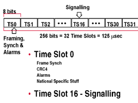
R2 signaling operates across E1 digital facilities. The E1 digital facilities carrier runs at 2.048 Mbps and has 32 time-slots. E1 time-slots are numbered TS0 to TS31, where TS1 through TS15 and TS17 through TS31 are used to carry voice, which is encoded with pulse code modulation (PCM), or to carry 64 kbps data. This image shows the 32 time-slots of an E1 frame:

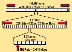
An E1 carrier can use a multiframe structure within a Super Frame (SF) format or it can run in a non-multiframe mode without cyclic redundancy check (CRC). The SF format contains sixteen consecutive frames numbered 0 to 15. Time-slot TS16 in frame 0 is used for SF alignment, and TS16 in the frames that remain (1 through 15) is used for CAS trunk signaling. TS16 uses four status bits, designated as A, B, C, and D, for signaling purposes. This multiframe structure is used for CRC, or error checking. This 16-frame multiframe structure (SF) allows a single 8-bit time slot to handle the line signaling for all 30 data channels. This diagram illustrates the E1 SF format:

R2 Signaling
The two elements to R2 signaling are line signaling (supervisory signals) and interregister signaling (call setup control signals). Most country variations in R2 signaling are with the interregister signaling configuration.
Line Signaling (Supervisory Signals)
You can use line signaling, which uses TS16 (bits A, B, C, and D), for supervisory purposes such as handshaking between two offices for call setup and termination. In the case of CCITT-R2 signaling, only bits A and B are used (bit C is set to 0 and bit D is set to 1). For two-way trunks, the supervision roles for forward and backward signaling vary on a call-by-call basis. This table illustrates the R2 supervision signal, transition, and direction used on digital trunks:
Note: An idle state is denoted when A=1 and B=0.
| Direction | Signal Type | Transition |
|---|---|---|
| Forward | Seizure | A,B: 1,0 to 0,0 |
| Forward | Clear-forward | A,B: 0,0 to 1,0 |
| Backward | Seizure Acknowledgment (ACK) | A,B: 1,0 to 1,1 |
| Backward | Answer | A,B: 1,1 to 0,1 |
| Backward | Clear-back | A,B: 0,1 to 1,1 |
| Backward | Release-guard | A,B: 0,1 to 1,0 |
Line signaling is defined with these types:
-
R2-Digital—R2 line signaling type ITU-U Q.421, typically used for PCM systems (where A and B bits are used).
-
R2-Analog—R2 line signaling type ITU-U Q.411, typically used for carrier systems (where a Tone/A bit is used).
-
R2-Pulse—R2 line signaling type ITU-U Supplement 7, typically used for systems that employ satellite links (where a Tone/A bit is pulsed).
Note: R2-Pulse reflects the same states as the analog signaling. But the analog signal is a steady state (continuous signal), while the pulsed signal stays on for only a short duration. Pulsed is just a single pulse to reflect the state change.
Refer to E1 R2 Signaling Configuration and Troubleshooting for more information on how to configure line signaling.
Interregister Signaling (Call Setup Control Signals)
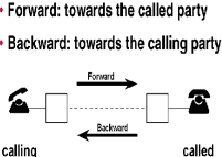
The concept of address signaling in R2 is slightly different than that used in other CAS systems. In R2 signaling, the exchanges are considered registers and the signaling between these exchanges is called interregister signaling. Interregister signaling uses forward and backward in-band multifrequency signals in each time slot to transfer called and calling party numbers, as well as the calling party category.
Note: Some countries use two-out-of-six in-band dual tone multifrequency (DTMF) instead of forward and backward in-band multifrequency signals.
Multifrequency signals used in interregister signaling are divided in forward signal groups (I and II), and backward signal groups (A and B). Interregister signaling starts after the "Seize-ACK" of the line. This diagram and table illustrate forward and backward signal information:

| Forward Signal Groups | Backward Signal Groups |
|---|---|
Group-I Signals
|
Group-A Signals
|
These interregister group sequence rules are used to identify the group to which the signal belongs:
-
The initial signal received by the incoming exchange is a Group I signal.
-
Outgoing exchanges consider backward signals as Group A signals.
-
Group A signals received by outgoing exchanges are used to identify whether the next signal is a Group B signal.
-
Group B signals always indicate an end-of-signaling sequence.
There are three types of interregister signaling:
-
R2-Compelled—When a tone-pair is sent from the switch (forward signal), the tones stay on until the remote end responds (sends an ACK) with a pair of tones that signals the switch to turn off the tones. The tones are compelled to stay on until they are turned off.
-
R2-Non-Compelled —The tone-pairs are sent (forward signal) as pulses so they stay on for a short duration. Responses (backward signals) to the switch (Group B) are sent as pulses. There are no Group A signals in non-compelled interregister signaling.
Note: Most installations use the non-compelled type of interregister signaling.
-
R2-Semi-Compelled—Forward tone-pairs are sent as compelled. Responses (backward signals) to the switch are sent as pulses. It is the same as compelled, except that the backward signals are pulsed instead of continuous.
Note: Do not use compelled signaling on slow (satellite) links. The call setup time is too large because of distance delays.
Most country-specific variations of R2 signaling are seen in interregister signaling. Unique E1 R2 signaling parameters for specific countries and regions are set when you issue the cas-custom command, followed by the country name command.
Refer to E1 R2 Signaling Configuration and Troubleshooting for more information on configuration of interregister signaling and cas-custom command parameters.
Related Information
- Digital CAS (R2, E&M, FXS, FXO)
- E1 R2 Signaling Configuration and Troubleshooting
- E1 R2 Signaling for the Cisco AS5300 and Cisco AS5200 Access Servers
- E1 R2 Signaling for the Cisco 3620 and 3640 Series Routers
- Command Lookup Tool ( registered customers only)
- Voice Technology Support
- Voice and Unified Communications Product Support
- Troubleshooting Cisco IP Telephony

- Technical Support & Documentation - Cisco Systems
 Feedback