Voice Network Signaling and Control
Available Languages
Contents
Introduction
This paper discusses the signaling techniques required to control voice transmission. These signaling techniques can be placed into one of three categories; supervision, addressing, or alerting. Supervision involves the detection of changes to the status of a loop or trunk. Once these changes are detected, the supervisory circuit generates a predetermined response. A circuit (loop) can close to connect a call, for example. Addressing involves passing dialed digits (pulsed or tone) to a private branch exchange (PBX) or central office (CO). These dialed digits provide the switch with a connection path to another phone or customer premises equipment (CPE). Alerting provides audible tones to the user, which indicate certain conditions such as an incoming call or a busy phone. A phone call cannot take place without all of these signaling techniques. In this document a discussion of specific signaling types within each category precedes an examination of basic call progress from call origination to termination.
Prerequisites
Requirements
There are no specific requirements for this document.
Components Used
This document is not restricted to specific software and hardware versions.
Conventions
Refer to Cisco Technical Tips Conventions for more information on document conventions.
Basic Call Progress
The progress of a telephone call with loop-start signaling in place can be divided into five phases; on-hook, off-hook, dialing, switching, ringing, and talking. Figure 1 shows the on-hook phase.
Figure 1 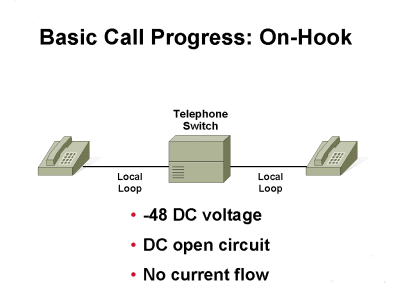
When the handset rests on the cradle, the circuit is on-hook. In other words, before a phone call is initiated, the telephone set is in a ready condition waiting for a caller to pick up its handset. This state is called on-hook. In this state, the 48-VDC circuit from the telephone set to the CO switch is open. The CO switch contains the power supply for this DC circuit. The power supply located at the CO switch prevents a loss of telephone service when the power goes out at the location of the telephone set. Only the ringer is active when the telephone is in this position. Figure 2 shows the off-hook phase.
Figure 2 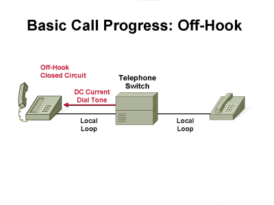
The off-hook phase occurs when the telephone customer decides to make a phone call and lifts the handset from the telephone cradle. The switch hook closes the loop between the CO switch and the telephone set and allows current to flow. The CO switch detects this current flow and transmits a dial tone (350- and 440-hertz [Hz] tones played continuously) to the telephone set. This dial tone signals the customer can begin to dial. There is no guarantee that the customer hears a dial tone right away. If all the circuits are used, the customer could have to wait for a dial tone. The access capacity of the CO switch used determines how soon a dial tone is sent to the caller phone. The CO switch generates a dial tone only after the switch has reserved registers to store the incoming address. Therefore, the customer cannot dial until a dial tone is received. If there is no dial tone, then the registers are not available. Figure 3 shows the dialing phase.
Figure 3 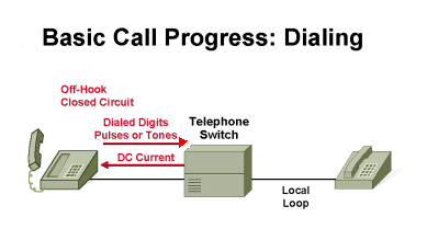
The dialing phase allows the customer to enter a phone number (address) of a telephone at another location. The customer enters this number with either a rotary phone that generates pulses or a touch-tone (push-button) phone that generates tones. These telephones use two different types of address signaling in order to notify the telephone company where a subscriber calls: Dual tone multifrequency (DTMF) dialing and Pulse dialing.
These pulses or tones are transmitted to the CO switch across a two-wire twisted-pair cable (tip and ring lines). Figure 4 shows the switching phase.
Figure 4 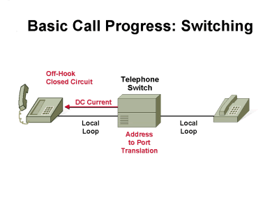
In the switching phase, the CO switch translates the pulses or tones into a port address that connects to the telephone set of the called party. This connection could go directly to the requested telephone set (for local calls) or go through another switch or several switches (for long-distance calls) before it reaches its final destination. Figure 5 shows the ringing phase.
Figure 5 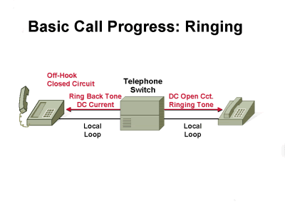
Once the CO switch connects to the called line, the swtich sends a 20-Hz 90V signal to this line. This signal rings the phone of the called party. While ringing the phone of the called party, the CO switch sends an audible ring-back tone to the caller. This ring-back lets the caller know that ringing occurs at the called party. The CO switch transmits 440 and 480 tones to the caller phone in order to generate a ring-back. These tones are played for a specific on time and off time. If the called party phone is busy, the CO switch sends a busy signal to the caller. This busy signal consists of 480- and 620-Hz tones. Figure 6 shows the talking phase.
Figure 6 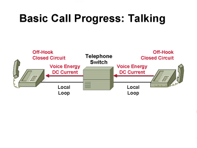
In the talking phase, the called party hears the phone ringing and decides to answer. As soon as the called party lifts the handset, an off-hook phase starts again, this time on the opposite end of the network. The local loop is closed on the called party side, so current starts to flow to the CO switch. This switch detects current flow and completes the voice connection back to the calling party phone. Now, voice communication can start between both ends of this connection.
Table 1 shows a summary of alerting tones that could be generated by the CO switch during a phone call.
Table 1 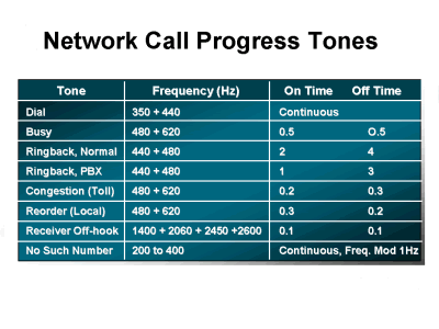
The progress tones in Table 1 are for North American phone systems. International phone systems can have a totally different set of progress tones. Everyone must be familiar with most of these call progress tones.
A Dial tone indicates that the telephone company is ready to receive digits from the user telephone.
A Busy tone indicates that a call cannot be completed because the telephone at the remote end is already in use.
A Ring-Back (normal or PBX) tone indicates that the telephone company is attempting to complete a call on behalf of a subscriber.
A Congestion progress tone is used between switches to indicate that congestion in the long distance telephone network currently prevents a telephone call from being progressed.
A Reorder tone indicates that all the local telephone circuits are busy, and thus prevents a telephone call from being processed.
A Receiver off-hook tone is the loud ringing that indicates the receiver of a phone is left off-hook for an extended period of time.
A No such number tone indicates that the number dialed cannot be found in the routing table of a switch.
Address Signaling and Tip and Ring
Address Signaling
North American Numbering Plan
The North American Numbering Plan (NANP) uses ten digits to represent a telephone number. These ten digits are divided into three parts: the area code, office code, and station code.
In the original NANP, the area code consisted of the first three digits of the telephone number and represented a region in North America (including Canada). The first digit was any number from 2 to 9, the second digit was 1 or 0, and the third digit was any number from 0 to 9. The office code consisted of the second three digits of the telephone number and uniquely identified a switch in the telephone network. The first digit was any number from 2 to 9, the second digit was any number from 2 to 9, and the third digit was any number from 0 to 9. The area code and office code could never be the same because the second digit of each code was always different. With this numbering system, the switch was able to determine whether this was a local call or long-distance call with the second digit of the area code. The station code consisted of the last four digits in the telephone number. This number uniquely identified a port within the switch that was connected to the telephone being called. Based on this ten-digit numbering system, an office code could have up to 10,000 different station codes. In order for a switch to have more than 10,000 connections, it has to have more office codes assigned to it.
An increase in the number of phone lines installed in homes, Internet access, and fax machine usage dramatically reduced the number of phone numbers available. This scenario prompted a change in the NANP. The present plan is basically the same as the old plan except for the area code and office code sections of the telephone number. The three digits for the area code and office code are now selected in the same fashion. The first digit can be any number from 2 to 9, and the second and third digits can be any number from 0 to 9. This scenario dramatically increases the number of area codes available, it in turn increases the number of station codes that can be assigned. If the call is a long-distance number, a one must be dialed before the 10-digit number.
International Numbering Plan
The International Numbering Plan is based on ITU-T specification E.164, an international standard that all countries must follow. This plan states that the telephone number in every country cannot be greater than 15 digits. The first three digits represent the country code, but each can choose whether to use all three digits. The remaining 12 digits represent the national specific number. For example, the country code for North America is 1. Therefore, when calling North America from another country, 1 must be dialed first in order to access the NANP. Then the ten digits required by the NANP are dialed. The 12 digits of the national specific number can be organized in any manner deemed appropriate by the specific country. Also, some countries can use a set of digits to indicate an outgoing international call. For example, 011 is used from within the United States to place an outgoing international call. Figure 7 illustrates network addressing in North America.
Figure 7 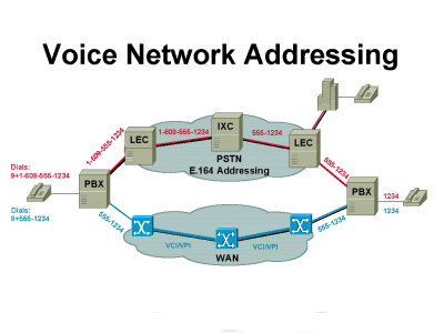
In this figure, the caller generates a call from within a customer premise that uses a PBX to access the Public Switched Telephone Network (PSTN). To get past the PBX, the caller must dial 9 first (this is how most PBXs are set up). Then, the caller must dial 1 for long distance and the ten-digit number of the telephone the caller wants to reach. The area code takes the caller through two switches, first a local switch and then an inter-exchange carrier (IXC) switch, which takes the call long distance. The office code (second three digits) takes the caller through a local switch again, and then to another PBX. Finally, the station code (last four digits) takes the caller to the telephone called.
Pulse Dialing
Pulse Dialing is an in-band signaling technique. It is used in analog telephones that have a rotary dialing switch. The large numeric dial-wheel on a rotary-dial telephone spins to send digits to place a call. These digits must be produced at a specific rate and within a certain level of tolerance. Each pulse consists of a "break" and a "make", which are achieved when the local loop circuit is opened and closed. The break segment is the time during which the circuit is open. The make segment is the time time during which the circuit is closed. Each time the dial is turned, the bottom of the dial closes and opens the circuit leading to the CO switch or PBX switch.
A "governor" inside the dial controls the rate at which the digits are pulsed; for example, when a subscriber dials a digit on the rotary dial to call someone, a spring winds. When the dial is released, the spring rotates the dial back to its original position, and a cam-driven switch opens and closes the connection to the telephone company. The number of consecutive opens and closes--or breaks and makes-- represents the dialed digits Therefore, if the digit 3 is dialed, the switch is closed and opened three times. Figure 8 represents the sequence of pulses that occur when a digit 3 is dialed with pulse dialing.
Figure 8 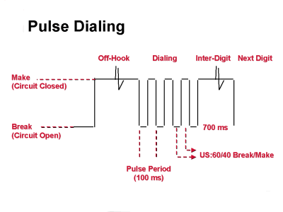
This illustration displays the two terms, make and break. When the telephone is off-hook, a make occurs and the caller receives a dial tone from the CO switch. Then the caller dials digits, which generate sequences of makes and breaks that occur every 100 milliseconds (ms). The break and make cycle must correspond to a ratio of 60 percent break to 40 percent make. Then the phone stays in a make state until another digit is dialed or the phone is put back to an on-hook (equivalent to a break) state. Dial pulse addressing is a very slow process because the number of pulses generated equates to the digit dialed. So, when a digit 9 is dialed, it generates nine make and break pulses. A digit 0 generates ten make and break pulses. In order to increase the speed of dialing, a new dialing technique (DTMF) was developed. Figure 9 shows the frequency tones generated by DTMF dialing (also called touch-tone dialing).
DTMF Dialing
Figure 9 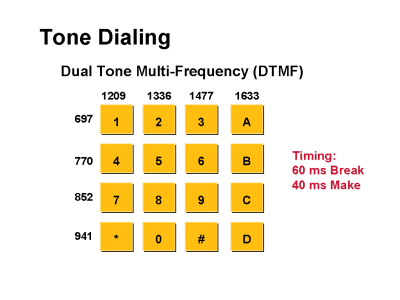
DTMF dialing is an in-band signaling technique just like pulse dialing. This technique is used in analog telephone sets that have a touch-tone pad. This dialing technique uses only two frequency tones per digit, as shown in Figure 9. Each button on the keypad of a touch-tone pad or a push-button telephone is associated with a set of high and low frequencies. On the keypad, each row of the key is identified by a low-frequency tone, and each column is associated with a high-frequency tone. The combination of both tones notify the telephone company of the number called, hence the term dual tone multifrequency. Therefore, when digit 0 is dialed, only frequency tones 941 and 1336 are generated instead of the ten make and break pulses generated by pulse dialing. The timing is still a 60-ms break and 40-ms make for each frequency generated. These frequencies were selected for DTMF dialing based on their insusceptibility to normal background noise.
Single-Frequency and Multifrequency Signaling
R1 and R2 signaling standards are used to transmit supervisory and address signaling information between voice network switches. They both use single-frequency signaling for transmission of supervisory information and multifrequency signaling for addressing information.
R2 Signaling
R2 signaling specifications are contained in ITU-T Recommendations Q.400 through Q.490. The physical connection layer for R2 is usually an E1 (2.048 megabits per second [Mbps]) interface that conforms to ITU-T standard G.704. The E1 digital facilities carrier runs at 2.048 Mbps and has 32 time-slots. E1 time-slots are numbered TS0 to TS31, where TS1 through TS15 and TS17 through TS31 are used to carry voice, which is encoded with pulse code modulation (PCM), or to carry 64 kbps data. This interface uses time slot 0 for synchronization and framing (same as for Primary Rate Interface [PRI]) and uses time slot 16 for ABCD signaling. There is a 16-frame multiframe structure that allows a single 8-bit time slot to handle the line signaling for all 30 data channels.
R2 Call Control and Signaling
Two types of signaling are involved: line signaling (supervisory signals) and inter-register signaling (call setup control signals). Line signaling involves supervisory information (on-hook and off-hook) and inter-register signaling deals with addressing. These are described in more detail in this document.
R2 Line Signaling
R2 uses channel-associated signaling (CAS). This means that, in the case of E1, one of the time slots (channels) is dedicated to signaling as opposed to the signaling used for T1. The latter uses the top bit of every time slot in every sixth frame.
This signaling is out-of-band signaling and uses ABCD bits in a similar manner to T1 robbed-bit signaling to indicate on-hook or off-hook status. These ABCD bits appear in time slot 16 in each of the 16 frames that make up a multiframe. Of these four bits, sometimes known as signaling channels, only two (A and B) are actually used in R2 signaling; the other two are spare.
In contrast to robbed-bit signaling types such as wink start, these two bits have different meanings in the forward and backward directions. However, there are no variants on the basic signaling protocol.
Line signaling is defined with these types:
R2-Digital—R2 line signaling type ITU-U Q.421, typically used for PCM systems (where A and B bits are used).
R2-Analog—R2 line signaling type ITU-U Q.411, typically used for carrier systems (where a Tone/A bit is used).
R2-Pulse—R2 line signaling type ITU-U Supplement 7, typically used for systems that employ satellite links (where a Tone/A bit is pulsed).
R2 Interregister Signaling
The transfer of call information (called and calling numbers, and so on) is performed with tones in the time slot used for the call (called in-band signaling).
R2 uses six signaling frequencies in the forward direction (from the initiator of the call) and a different six frequencies in the backward direction (from the party who answers the call). These inter-register signals are of the multifrequency type with a two-out-of-six in-band code. Variations on R2 signaling that use only five of the six frequencies are known as decadic CAS systems.
Inter-register signaling is generally performed end-to-end by a compelled procedure. This means that tones in one direction are acknowledged by a tone in the other direction. This type of signaling is known as multifrequency compelled (MFC) signaling.
There are three types of inter-register signaling:
R2-Compelled—When a tone-pair is sent from the switch (forward signal), the tones stay on until the remote end responds (sends an ACK) with a pair of tones that signals the switch to turn off the tones. The tones are compelled to stay on until turned off.
R2-Non-Compelled—The tone-pairs are sent (forward signal) as pulses, so they stay on for a short duration. Responses (backward signals) to the switch (Group B) are sent as pulses. There are no Group A signals in non-compelled inter-register signaling.
Note: Most installations use non-compelled inter-register signaling.
R2-Semi-Compelled—Forward tone-pairs are sent as compelled. Responses (backward signals) to the switch are sent as pulses. This scenario is the same as compelled, except that the backward signals are pulsed instead of continuous.
Features that can be signaled include:
-
Called or calling party number
-
Call type (transit, maintenance, and so on)
-
Echo-suppressor signals
-
Calling party category
-
Status
R1 Signaling
R1 signaling specifications are contained in ITU-T Recommendations Q.310 through Q.331. This document contains a summary of the main points . The physical connection layer for R1 is usually a T1 (1.544-Mbps) interface that conforms to ITU-T standard G.704. This standard uses the 193rd bit of the frame for synchronization and framing (same as T1).
R1 Call Control and Signaling
Again two types of signaling are involved: line signaling and register signaling. Line signaling involves supervisory information (on-hook and off-hook) and register signaling deals with addressing. Both are discussed in more detail:
R1 Line Signaling
R1 uses in-slot CAS by bit robbing the eighth bit of each channel every sixth frame. This type of signaling uses ABCD bits in an identical manner to T1 robbed-bit signaling to indicate on-hook or off-hook status.
R1 Register Signaling
The transfer of call information (called and calling numbers, and so on) is performed with tones in the time slot used for the call. This type of signaling is also called in-band signaling.
R1 uses six signaling frequencies that are 700 to 1700 Hz in 200-Hz steps. These inter-register signals are of the multifrequency type and use a two-out-of-six in-band code. The address information contained in the register signaling is preceded by a KP tone (start-of-pulsing signal) and terminated by a ST tone (end-of-pulsing signal).
Features that can be signaled include:
-
Called-party number
-
Call status
Tip and Ring Lines
Figure 10 illustrates tip and ring lines in a plain old telephone service (POTS) network.
Figure 10 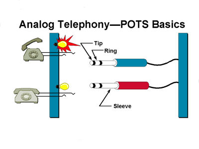
The standard way to transport voice between two telephone sets is to use tip and ring lines. Tip and ring lines are the twisted pair of wires that connect to your phone by way of an RJ-11 connector. The sleeve is the ground lead for this RJ-11 connector.
Loop-Start Signaling
Loop-start signaling is a supervisory signaling technique that provides a way to indicate on-hook and off-hook conditions in a voice network. Loop-start signaling is used primarily when the telephone set is connected to a switch. This signaling technique can be used in any of these connections:
-
Telephone set to CO switch
-
Telephone set to PBX switch
-
Telephone set to foreign exchange station (FXS) module (interface)
-
PBX switch to CO switch
-
PBX switch to FXS module (interface)
-
PBX switch to foreign exchange office (FXO) module (interface)
-
FXS module to FXO module
Analog Loop-Start Signaling
Figures 11 through 13 illustrate loop-start signaling from a telephone set, PBX switch, or FXO module to a CO switch or FXS module. Figure 11 shows the idle state for loop-start signaling.
Figure 11 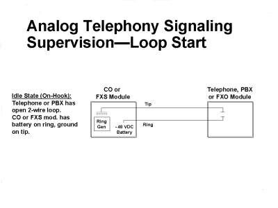
In this idle state, the telephone, PBX, or FXO module has an open two-wire loop (tip and ring lines open). It could be a telephone set with the handset on-hook, or a PBX or FXO module that generates an open between the tip and ring lines. The CO or FXS waits for a closed loop that generates a current flow. The CO or FXS have a ring generator connected to the tip line and –48VDC on the ring line. Figure 12 shows an off-hook state for a telephone set or a line seizure for a PBX or FXO module.
Figure 12 
In this illustration, a telephone set, PBX, or FXO module closes the loop between the tip and ring lines. The telephone takes its handset off-hook or the PBX or FXO module closes a circuit connection. The CO or FXS module detects current flow and then generates a dial tone, which is sent to the telephone set, PBX, or FXO module. This indicates that the customer can start to dial. What happens when there is an incoming call from the CO switch or FXS module? Figure 13 shows this situation.
Figure 13 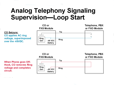
In the illustration, the CO or FXS module seizes the ring line of the telephone, PBX, or FXO module called by superimposing a 20-Hz, 90-VAC signal over the –48VDC ring line. This procedure rings the called party telephone set or signals the PBX or FXS module that there is an incoming call. The CO or FXS module removes this ring once the telephone set, PBX, or FXO module closes the circuit between the tip and ring lines. The telephone set closes the circuit when the called party picks up the handset. The PBX or FXS module closes the circuit when it has an available resource to connect to the called party. The 20-Hz ringing signal generated by the CO switch is independent of the user lines and is the only way to let a user know that there is an incoming call. The user lines do not have a dedicated ring generator. Therefore, the CO switch must cycle through all the lines it must ring. This cycle takes about four seconds. This delay in ringing a phone causes a problem, known as glare, when the CO switch and the telephone set PBX, or FXO module seize a line simultaneously. When this happens, the person who initiates the call is connected to the called party almost instantaneously, with no ring-back tone. Glare is not a major problem from the telephone set to the CO switch because an occasional glare situation can be tolerated by the user. Glare becomes a major problem, when a loop-start is used from the PBX or FXO module to the CO switch or FXS module because more call traffic is involved. Therefore, the chance of glare increases. This scenario explains why loop-start signaling is used primarily when a connection is made from the telephone set to a switch. The best way to prevent glare is to use ground-start signaling, which is covered in a later section.
Digital Loop-Start Signaling for 26/36/37xx platforms
These diagrams show the bit status for ABCD bits for FXS/FXO loop-start signaling as it applies to 26/36/37xx platforms:
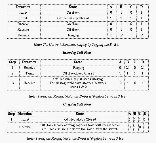
Digital Loop-Start Signaling for AS5xxx
These diagrams show the bit status of AB bits for FXS/FXO loop-start signaling as it applies to only AS5xxx platforms. This is not applicable to 26/36/37xx platforms. This mode of operation is most commonly used in off-premise extension (OPX) applications. This is a two-state signaling scheme, using the "B bit" for signaling.
Idle Condition:
To FXS: A bit = 0, B bit = 1

From FXS: A bit = 0, B bit = 1
FXS Originates:
Step 1: FXS changes A bit to 1, signaling the FXO to close the loop.
To FXS: A bit = 0, B bit = 1

From FXS: A bit = 1, B bit = 1
FXO Originates
Step 1: FXO sets the B bit to 0. The B bit toggles with the ring generation:
To FXS: A bit = 0, B bit = 1

From FXS: A bit = 1, B bit = 1
Loop-Start Testing
How to test the signaling states of a loop-start trunk is discussed with reference to two viewpoints: from the demarc looking toward the CO and from the demarc looking toward the PBX.
Idle Condition (on-hook, initial state)
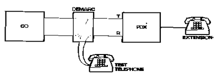
The idle condition is represented in Figure 14. The bridging clips are removed to isolate the CO from the PBX.
Looking toward the PBX, an open condition is observed between the T-R leads at the demarc.
Looking toward the CO from the demarc, ground is observed on the T lead and –48V is observed on the R lead. A voltmeter connected between T and R on the CO side of the demarc ideally reads close to –48V.
Figure 14 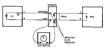
Outgoing (off-hook)
In order to test the operation toward the CO, remove the bridging clips and attach a test telephone set across the T-R leads toward the CO. The test set provides loop closure. The CO detects the loop closure, attaches a digit receiver to the circuit, establishes an audio path, and transmits dial tone toward the PBX. (See Figure 15.)
Figure 15 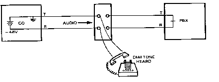
Once a dial tone is received by the test telephone, you can proceed to dial with either DTMF or dial-pulse signaling as allowed by the CO. Some COs are equipped to receive only dial-pulse addressing. Those equipped to receive DTMF can also receive dial pulse. When the first dialed digit is received, the CO removes dial tone.
After all digits have been dialed, the digit receiver is removed at the CO, and the call is routed to the distant station or switch. The audio path is extended over the outgoing facility, and audible call-progress tones are returned to the test telephone. Once the call is answered, voice signals can be heard over the audio path.
Incoming (ringing at destination)
A test telephone at the demarc can also be used to test loop-start trunks for incoming call operation. The test setup is the same as for outgoing calls. Typically the PBX technician calls a CO technician on another line and asks the CO technician to call the PBX on the trunk under test. The CO applies ringing voltage to the trunk. Ideally, the test phone at the demarc rings. The PBX technician answers the call on the test phone. If the technicians can talk to each other over the trunk under test, the trunk functions normally.
Tests between the PBX and the demarc with bridging clips removed are difficult. The loop-start interface circuits in most PBXs require battery voltage from the CO for their operation. If the voltage is not present, the trunk cannot be selected for outgoing calls. The usual procedure is to test the trunk from the demarc to the CO, first with the bridging clips removed as described, and then after installing the bridging clips. If the trunk fails to function properly when connected to the PBX, the problem is probably in the PBX or in the wiring between the PBX and the demarc.
Ground-Start Signaling
Ground-start signaling is another supervisory signaling technique, like loop-start, that provides a way to indicate on-hook and off-hook conditions in a voice network. Ground-start signaling is used primarily in switch-to-switch connections. The main difference between ground-start and loop-start signaling is that ground-start requires ground detection to occur in both ends of a connection before the tip and ring loop can be closed.
Although loop-start signaling works when you use your telephone at home, ground-start signaling is preferable when there are high-volume trunks involved at telephone switching centers. Because ground-start signaling uses a request and/or confirm switch at both ends of the interface, it is preferable over FXOs and other signaling methods on high-usage trunks.
Analog Ground-Start Signaling
Figures 16 through 19 cover ground-start signaling only from a CO switch or FXS module to a PBX or FXO module. Figure 16 shows the idle (on-hook) condition of ground-start signaling.
Figure 16 
In the illustration, both the tip and ring lines are disconnected from ground. The PBX and FXO constantly monitor the tip line for ground, and the CO and FXS constantly monitor the ring line for ground. Battery (–48 VDC) is still connected to the ring line just as in loop-start signaling. Figure 17 shows a call originating from a PBX or FXO.
Figure 17 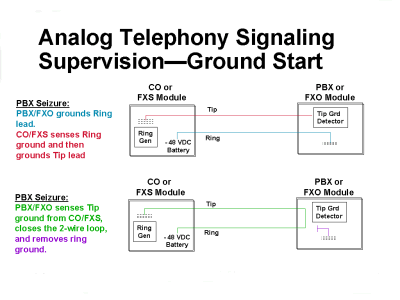
In the illustration, a PBX or FXO grounds the ring line to indicate to the CO or FXS that there is an incoming call. The CO or FXS senses the ring ground and then grounds the tip lead to let the PBX or FXO know that it is ready to receive the incoming call. The PBX or FXO senses the tip ground and closes the loop between the tip and ring lines in response. It also removes the ring ground. This process completes the voice connection to the CO or FXS, and voice communication can start. Figure 18 displays a call coming from the CO or FXS.
Figure 18 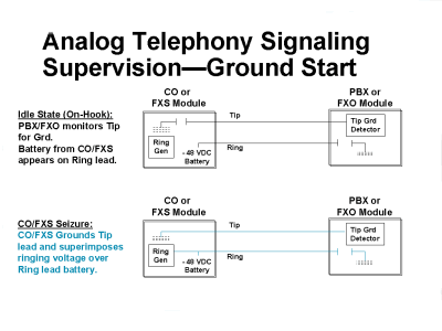
In Figure 18, the CO or FXS grounds the tip line and then superimposes a 20-Hz 90-VAC ringing voltage over the ring line to alert the PBX or FXO of an incoming call. Figure 19 shows the final phase of ground-start signaling.
Figure 19 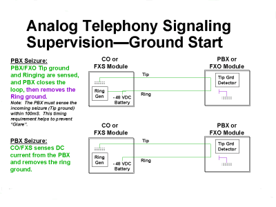
In this illustration, PBX or FXO senses both the tip ground and ringing. When the PBX or FXO has available resources to make the connection, the PBX or FXO closes the loop between the tip and ring lines and removes the ring ground. The CO or FXS senses the current flowing from the tip and ring loop, and then removes the ringing tone. The PBX or FXO must sense the tip ground and ringing within 100 ms or the circuit times out and the caller has to reorder the call. This 100-ms timeout helps prevent glare.
Digital Ground-Start Signaling for 26/36/37xx platforms
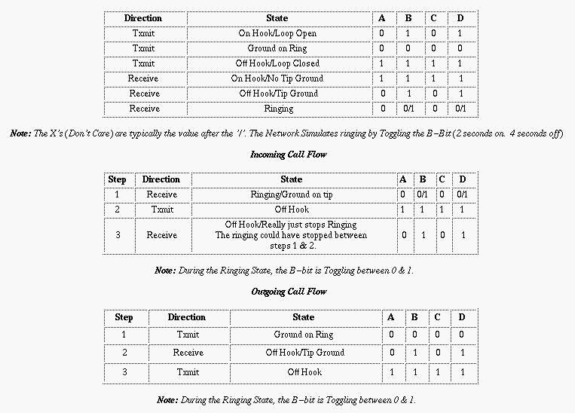
These diagrams show the bit status for ABCD bits for FXS/FXO loop-start signaling as it applies to 26/36/37xx platforms.
Note: This diagram is from the router FXO perspective.
Note: Disconnect Supervision is done with A bit.
Digital Ground-Start Signaling for AS5xxx platforms
These diagrams show the bit status of AB bits for FXS/FXO loop-start signaling as it applies to only AS5xxx platforms. This is not applicable to 26/36/37xx platforms. This mode of operation is most commonly used in foreign exchange (FX) trunk applications.
FXS originates:
Idle condition:
To FXS: A bit = 1, B bit = 1

From FXS: A bit = 0, B bit = 1
Step 1: FXS originates the call. B bit from FXS goes to 0:
To FXS: A bit = 1, B bit = 1

From FXS: A bit = 0, B bit = 0 (FXS originating call)
Step 2: A bit from FXO goes to 0:
To FXS: A bit = 0 (FXO responding), B bit = 1

From FXS: A bit = 0, B bit = 0
Step 3: FXS responds by transmitting A=1, B=1 to FXO:
To FXS: A bit = 0, B bit = 1

From FXS: A bit = 1, B bit = 1
FXO Originates:
Step 1: FXO changes the A and B bits from 1 to 0 (B bit follows ring cycle):
To FXS: A bit = 0, B bit = 0

From FXS: A bit = 0, B bit = 1
Step 2: FXS changes the A bit from 0 to 1 in response. FXO trips the ring generator in response. When the ring generator is tripped, the FXO returns the B bit to 1:
To FXS: A bit = 0, B bit = 1

From FXS: A bit = 1, B bit = 1
Ground-Start Testing
Tests for ground-start trunks are similar to tests for loop-start trunks. However, some tests between the PBX and the demarc, with bridging clips removed, can usually be made.
Idle Condition (on hook)
The idle condition is represented in Figure 20. The bridging clips are removed to isolate the PBX from the CO. Looking toward the PBX, –48V is observed on the T lead, and the R lead is open. Looking toward the CO, –48V is observed on the R lead, and the T lead is open.
Figure 20 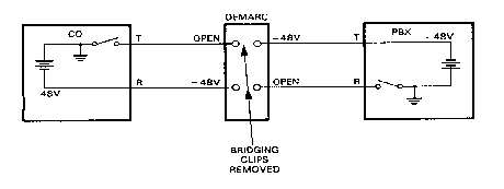
Ideally, a voltmeter connected from R to ground on the CO side of the demarc, or from T to ground on the PBX side, reads approximately –48V. An ohmmeter connected between T and ground on the CO side reads a very high resistance. Many PBXs have some voltage present between R and ground in the idle state. Erroneous measurements and damage to the meter can occur if resistance measurements are attempted. Refer to the PBX manufacturer's technical manual before you measure R-to-ground resistance on the PBX side of the demarc.
Outgoing (off hook)
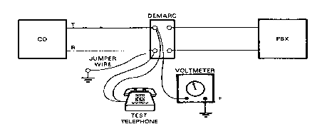
To test a ground-start trunk for outgoing calls, remove the bridging clips and connect a test telephone and voltmeter; then proceed with these steps:
-
Observe the voltmeter. With the test telephone on-hook, ideally the meter reads near 0.0V.
-
Go off-hook and listen. Ideally, there is no dial tone.
-
Observe the meter. Ideally, it reads near –48V.
-
Momentarily ground the R lead with a jumper wire and listen for a dial tone again. Ideally, a dial tone is heard shortly after the ground is removed.
-
Observe the voltmeter. The reading is much lower than before, which indicates that the CO is sending T ground.
-
Dial a station or a milliwaft test termination number. If the call completes, audio can be heard.
Incoming (Ringing at Destination)
Ground-start trunks can be tested for incoming call operation with a test telephone with exactly the same procedure as for loop-start trunks.
Loop Current Testing
For reliable operation, loop-start and ground-start trunks must have at least 23 milliamperes (mA) of direct current flowing when the loop is closed. Less than 23 mA results in erratic operation such as intermittent dropouts and inability to seize. If loop current is marginal, the trunk can test well with a test telephone, but operate erratically when connected to the PBX. Whenever a trunk operates erratically, loop current must be measured with a circuit test set.
Figure 22 illustrates the test setup. With the bridging clips removed, connect the green test lead to T and the red test lead to R on the CO side of the demarc. The yellow lead is not used for this test.
Figure 22 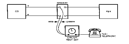
In order to measure loop current, go off-hook with the test telephone and listen for a dial tone. When you test a ground-start trunk, momentarily ground the R lead. When dial tone is obtained, press the Push to Measure button on the test set and read the current on the loop mA scale. Ideally, the reading is between 23 and 100 mA.
DID Trunk Testing
The idle condition is represented in Figure 23. Looking toward the PBX, ground is observed on the T, and battery is observed on the R lead. Looking toward the C0, a high-resistance loop is observed between T and R.
Figure 23 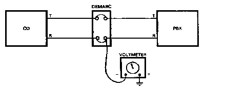
When the call is answered, the PBX places the battery on the T lead and ground on the R lead. This condition is known as a T-R reversal. This voltage reversal can be observed on the voltmeter. Because of the reversal of battery and ground on the T-R leads, this type of signaling is called loop reverse battery.
Call Disconnect
If the CO disconnects first, a brief voltage increase is observed while the loop in the CO switch goes from low to high resistance. This process is followed by a voltage reversal when the PBX goes on-hook.
If the PBX disconnects first, a voltage reversal is observed, followed by an increase in voltage when the CO goes on-hook and the CO loop goes from low to high resistance.
Make several test calls. After each test call, the bridging clips must be removed and the circuit tested to ensure that it has returned to the idle condition.
Demarc to PBX
Many PBXs can be tested for direct inward dial (DID) operation from the demarc with the bridging clips removed. Perform these steps:
-
Go off-hook with the test telephone.
-
Dial the one- to four-digit address of a PBX extension.
-
If the called extension rings, go to Step 4.
-
Attempt a conversation between the test telephone and the called extension. If good audio transmission occurs, then the PBX and trunk function well as far as the demarc.
-
If problems occur at Steps 3 or 4, then the DID operation is faulty and must be corrected.
E&M Signaling
Another signaling technique used mainly between PBXs or other network-to-network telephony switches (Lucent 5 Electronic Switching System [5ESS], Nortel DMS-100, and so on.) is known as E&M. E&M signaling supports tie-line type facilities or signals between voice switches. Instead of superimposing both voice and signaling on the same wire, E&M uses separate paths, or leads, for each. E&M is commonly referred to as ear and mouth or receive and transmit. There are five types of E&M signaling, as well as two different wiring methods (two-wire and four-wire). Table 1 shows that several of the E&M signaling types are similar.
| Type | M-Lead Off-hook | M-Lead on-hook | E-Lead Off-hook | E-Lead on-hook |
|---|---|---|---|---|
| I | Battery | Ground | Ground | Open |
| II | Battery | Open | Ground | Open |
| III | Loop Current | Ground | Ground | Open |
| IV | Ground | Open | Ground | Open |
| V | Ground | Open | Ground | Open |
| SSDC5 | Earth On | Earth Off | Earth On | Earth Off |
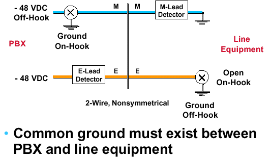
Four-wire E&M Type I signaling is actually a six-wire E&M signaling interface common in North America. One wire is the E-lead; the second wire is the M-lead, and the remaining two pairs of wires serve as the audio path. In this arrangement, the PBX supplies power, or battery, for both M- and E-leads.
Type II, III, and IV are eight-wire interfaces. One wire is the E-lead, the other wire is the M-lead. Two other wires are signal ground (SG) and signal battery (SB). In Type II, SG and SB are the return paths for the E-lead and M-lead, respectively.
Type V is another six-wire E&M signaling type and the most common E&M signaling form used outside of North America. In Type V, one wire is the E-lead and the other wire is the M-lead.
Similar to type V, SSDC5A differs in that on- and off-hook states are backward to allow for fail-safe operation. If the line breaks, the interface defaults to off-hook (busy). Of all the types, only types II and V are symmetrical (can be back-to-back with a crossover cable). SSDC5 is most often found in England. The Cisco 2600/3600 series currently supports types I, II, III, and V utilizing both two- and four-wire implementations. This illustration depicts two-wire and four-wire E&M signaling connections. Voice travels over the tip and ring lines. Signaling occurs over E&M lines.
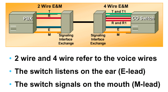
This figure illustrates type 1 E&M signaling with a two-wire line:
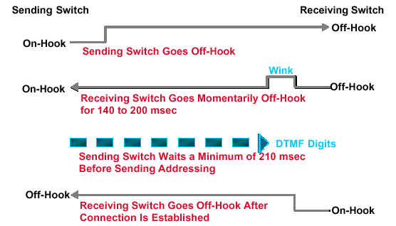
This illustration shows the process that takes place during wink start signaling:
This figure displays the immediate wink start signaling process:

Digital E&M Signaling
Digital E&M signaling is a two-state signaling scheme (on-hook and off-hook) commonly used on digital four-wire CO and tie trunks. "A bit" signaling transmits the signaling state. The "B bit" (or B, C, D bits in the case of extended superframe [ESF]) follows the same state as the A bit.
Idle Condition
To PBX B: A bit = 0, B bit = 0

From PBX B: A bit = 0, B bit = 0
PBX A Goes off-hook
To PBX B: A bit = 1, B bit = 1

From PBX B: A bit = 0, B bit = 0
PBX B Answers
To PBX B: A bit = 1, B bit = 1

From PBX B: A bit = 1, B bit = 1
Note: The originating switch can receive dial tone or wink back from the distant end after the call is initiated, depending on the application.
E&M Tie Trunk Testing
Since the PBXs at both ends of the tie trunk are part of the same private network, private network technicians can perform end-to-end tests on the trunk, even though the transmission path can include leased facilities in the public network. Technicians at both ends of the trunk work together, and coordinate their activities by talking over each other's facilities. These testing procedures cover tests of of only E&M signaling types I and II.
Type I
In order to test Type I E&M signaling, bridging clips are removed from the E- and M-leads at both ends. Ohmmeters are connected between the E leads and ground. When the M-lead at one end of the trunk is jumpered to –48V, ideally the ohmmeter reading at the other end goes from open to a very low resistance. This indicates E-lead ground. (See Figure 27.)
Figure 27 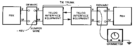
Type II
The test setup for Type II is illustrated in Figure 28. Bridging clips are removed only from the M and signal battery (SB) leads. Voltmeters are connected between E and signal ground (SG). Ideally, under idle conditions the voltmeters read battery voltage from the PBX, approximately –48V. When a jumper wire is connected between M and SB at one end of the trunk, ideally the voltmeter reading at the far end decreases to a low value, which indicates E-lead ground.
Figure 28 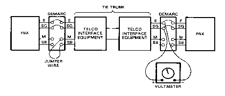
ITU-T Signaling System 7
Common Channel Signaling Systems
Common channel signaling (CCS) systems are usually High-level Data Link Control (HDLC)-based message-oriented signaling systems. Within the United States PSTN, the original implementation of CCS started in 1976, and was known as CCIS (common channel interoffice signaling). This signaling is similar to ITU-T's Signaling System 6 (SS6). The CCIS protocol operated at relatively low bit rates (2.4K, 4.8K, 9.6K), but transported messages that were only 28 bits long. However, CCIS could not adequately support an integrated voice and data environment. Therefore, a new HDLC-based signaling standard and ITU-T recommendation was developed: Signaling System 7.
First defined by the ITU-T in 1980, the Swedish Post, Telephone, and Telegraph (PTT) started SS7 trials in 1983, and some European countries are now entirely SS7-based.
Within the United States, Bell Atlantic began implementing SS7 in 1988, among the first Bell operating companies (BOCs), if not the first, to do so.
Currently, most of the long-distance networks and local-exchange-carrier networks have migrated to implementations of ITU-T's Signaling System 7 (SS7). By 1989, AT&T had converted its entire digital network to SS7; and US Sprint is SS7-based. However, many Local Exchange Carriers (LECs) are still in the process of upgrading their networks to SS7 because the number of switch upgrades required for SS7 support impacts the LECs much more heavily than the ICs. The slow deployment of SS7 within the LECs is also, in part, responsible for delays incorporating ISDN within the United States.
There are three versions of SS7 protocols at the present time:
-
ITU-T version (1980, 1984) detailed in ITU-T Q.701 - Q.741
-
AT&T and Telecom Canada (1985)
-
ANSI (1986)
Signaling System 7 U.S. PSTN Features
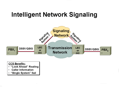
SS7 currently provides support for POTS through the use of a telephony user part (TUP), which defines the messages that are used to support this service. An additional ISDN user part (ISUP) has been defined that supports ISDN transport. Eventually, since the ISUP includes translations from POTS to ISDN, the ISUP is expected to replace the TUP. Figure 29 shows where SS7 takes control of the voice network.


 Feedback