Remote-Edge AP (REAP) with Lightweight APs and Wireless LAN Controllers (WLCs) Configuration Example
Available Languages
Contents
Introduction
Remote-edge access point (REAP) capabilities introduced with Cisco Unified Wireless Network allow remote deployment of the Cisco Lightweight Access Points (LAPs) from the wireless LAN (WLAN) controller (WLC). This makes them ideal for branch-office and small retail locations. This document explains how to deploy a REAP-based WLAN network with use of the Cisco 1030 Series LAP and 4400 WLCs.
Prerequisites
Requirements
Ensure that you meet these requirements before you attempt this configuration:
-
Knowledge of WLCs and how to configure the WLC basic parameters
-
Knowledge of the REAP mode of operation in a Cisco 1030 LAP
-
Knowledge of the configuration of an external DHCP server and/or Domain Name System (DNS) server
-
Knowledge of Wi-Fi Protected Access (WPA) concepts
Components Used
The information in this document is based on these software and hardware versions:
-
Cisco 4400 Series WLC that runs firmware release 4.2
-
Cisco 1030 LAP
-
Two Cisco 2800 Series Routers that run Cisco IOS® Software Release 12.2(13)T13
-
Cisco Aironet 802.11a/b/g Client Adapter that runs firmware release 3.0
-
Cisco Aironet Desktop Utility version 3.0
The information in this document was created from the devices in a specific lab environment. All of the devices used in this document started with a cleared (default) configuration. If your network is live, make sure that you understand the potential impact of any command.
Conventions
Refer to Cisco Technical Tips Conventions for more information on document conventions.
Background Information
REAP mode enables a LAP to reside across a WAN link, and still be able to communicate with the WLC and provide the functionality of a regular LAP. REAP mode is supported only on the 1030 LAPs at this point.
In order to provide this functionality, the 1030 REAP separates the Lightweight Access Point Protocol (LWAPP) control plane from the wireless data plane. Cisco WLCs are still used for centralized control and management in the same way that regular LWAPP-based access points (APs) are used, while all user data are bridged locally at the AP. Access to local network resources is maintained throughout WAN outages.
REAP APs support two modes of operation:
-
Normal REAP mode
-
Standalone mode
The LAP is set in normal REAP mode when the WAN link between the REAP AP and the WLC is up. When LAPs operate in normal REAP mode, they can support up to 16 WLANs.
When the WAN link between the WLC and the LAP goes down, the REAP-enabled LAP switches to standalone mode. While in standalone mode, the REAP LAPs can support only one WLAN independently without the WLC, if the WLAN is configured with either Wired Equivalent Privacy (WEP) or any local authentication method. In this case, the WLAN that the REAP AP supports is the first WLAN that is configured on the AP, WLAN 1. This is because most of the other authentication methods need to pass information to and from the controller and, when the WAN link is down, this operation is not possible. In standalone mode, the LAPs support a minimal set of features. This table shows the set of features that a REAP LAP supports when it is in standalone mode in comparison with the features that a REAP LAP supports in normal mode (when the WAN link is up and communication to the WLC is up):
Features That a REAP LAP Supports in Normal REAP Mode and in Standalone Mode 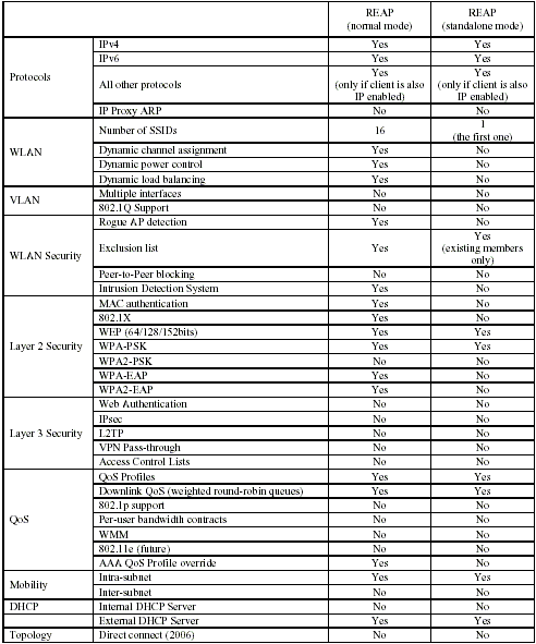
The table shows that multiple VLANs are not supported on REAP LAPs in both modes. Multiple VLANs are not supported because REAP LAPs can only reside on a single subnet because they cannot perform IEEE 802.1Q VLAN tagging. Therefore, traffic on each of the service set identifiers (SSIDs) terminates on the same subnet as the wired network. As a result, data traffic is not separated on the wired side even though wireless traffic may be segmented over the air between SSIDs.
Refer to REAP Deployment Guide at the Branch Office for more information on REAP deployment, and how to manage REAP and its limitations.
Configure
In this section, you are presented with the information to configure the features described in this document.
In order to configure the devices to implement the network setup, complete these steps:
Network Diagram
This document uses this network setup:
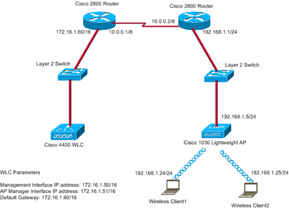
The main office connects to the branch office with use of a leased line. The leased line terminates on 2800 series routers at each end. This example uses Open Shortest Path First (OSPF) Protocol to route data on the WAN link with PPP encapsulation. The 4400 WLC is in the main office and the 1030 LAP must be deployed at the remote office. The 1030 LAP must support two WLANs. Here are the parameters for the WLANs:
-
WLAN 1
-
SSID—SSID1
-
Authentication—Open
-
Encryption—Temporal Key Integrity Protocol (TKIP) (WPA Pre-Shared Key [WPA-PSK])
-
-
WLAN 2
-
SSID—SSID2
-
Authentication—Extensible Authentication Protocol (EAP)
-
Encryption—TKIP
Note: For WLAN 2, the configuration in this document uses WPA (802.1x authentication and TKIP for encryption).
-
You must configure the devices for this setup.
Configure the WLC for Basic Operation and Configure WLANs
You can use the startup configuration wizard on the command-line interface (CLI) in order to configure the WLC for basic operation. Alternatively, you can also use the GUI in order to configure the WLC. This document explains the configuration on the WLC with use of the startup configuration wizard on the CLI.
After the WLC boots for the first time, it directly enters into the startup configuration wizard. You use the configuration wizard to configure basic settings. You can run the wizard on the CLI or the GUI. Here is an example of the startup configuration wizard:
Welcome to the Cisco Wizard Configuration Tool
Use the '-' character to backup
System Name [Cisco_33:84:a0]: WLC_MainOffice
Enter Administrative User Name (24 characters max): admin
Enter Administrative Password (24 characters max): *****
Management Interface IP Address: 172.16.1.50
Management Interface Netmask: 255.255.0.0
Management Interface Default Router: 172.16.1.60
Management Interface VLAN Identifier (0 = untagged):
Management Interface Port Num [1 to 4]: 1
Management Interface DHCP Server IP Address: 172.16.1.1
AP Manager Interface IP Address: 172.16.1.51
AP-Manager is on Management subnet, using same values
AP Manager Interface DHCP Server (172.16.1.1):
Virtual Gateway IP Address: 1.1.1.1
Mobility/RF Group Name: Main
Network Name (SSID): SSID1
Allow Static IP Addresses [YES][no]: Yes
Configure a RADIUS Server now? [YES][no]: no
Warning! The default WLAN security policy requires a RADIUS server.
Please see documentation for more details.
Enter Country Code (enter 'help' for a list of countries) [US]:
Enable 802.11b Network [YES][no]: Yes
Enable 802.11a Network [YES][no]: Yes
Enable 802.11g Network [YES][no]: Yes
Enable Auto-RF [YES][no]: Yes

Configuration saved!
Resetting system with new configuration...
This example configures these parameters on the WLC:
-
System name
-
Management interface IP address
-
AP-manager interface IP address
-
Management interface port number
-
Management interface VLAN identifier
-
Mobility group name
-
SSID
-
Many other parameters
These parameters are used to set up the WLC for basic operation. As the WLC output in this section shows, the WLC uses 172.16.1.50 as the management interface IP address and 172.16.1.51 as the AP-manager interface IP address. In order to configure the two WLANs for your network, complete these steps on the WLC:
-
From the WLC GUI, click WLANs in the menu at the top of the window.
The WLANs window appears. This window lists the WLANs that are configured on the WLC. Because you configured one WLAN with use of the startup configuration wizard, you must configure the other parameters for this WLAN.
-
Click Edit for the WLAN SSID1.
Here is an example:
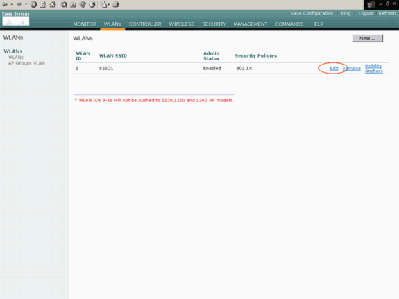
The WLANs > Edit window appears. In this window, you can configure the parameters that are specific to the WLAN, which includes General Policies, Security Policies, RADIUS server, and others.
-
Make these selections in the WLANs > Edit window:
-
In the General Policies area, check the Enabled check box beside Admin Status in order to enable this WLAN.
-
Choose WPA from the Layer 2 Security drop-down menu in order to use WPA for WLAN 1.
-
Define the WPA parameters at the bottom of the window.
In order to use WPA-PSK on WLAN 1, check the Enabled check box beside Pre-Shared Key in the WPA Parameters area and enter the passphrase for WPA-PSK. WPA-PSK will use TKIP for encryption.
Note: The WPA-PSK passphrase must match the passphrase that is configured on the client adapter in order for WPA-PSK to work.
-
Click Apply.
Here is an example:
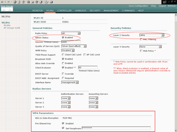
You have configured WLAN 1 for WPA-PSK encryption.
-
-
In order to define WLAN 2, click New in the WLANs window.
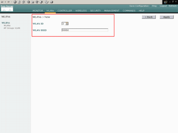
The WLAN > New window appears.
-
In the WLAN > New window, define the WLAN ID and the WLAN SSID, and click Apply.
Here is an example:
The WLAN > Edit window for the second WLAN appears.
-
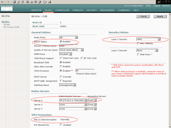
Make these selections in the WLANs > Edit window:
-
In the General Policies area, check the Enabled check box beside Admin Status in order to enable this WLAN.
-
Choose WPA from the Layer 2 Security drop-down menu in order to configure WPA for this WLAN.
-
In the Radius Servers area, choose the appropriate RADIUS server to use for authentication of the clients.
-
Click Apply.
Here is an example:
-
Note: This document does not explain how to configure the RADIUS servers and EAP authentication. For information on how to configure EAP authentication with WLCs, refer to EAP Authentication with WLAN Controllers (WLC) Configuration Example.
Prime the AP for Installation at the Remote Site
Priming is a process by which LAPs get a list of controllers to which they can connect. LAPs are informed of all controllers in the mobility group as soon as they connect to a single controller. In this way, the LAPs learn all the information they need in order to join any controller in the group.
In order to prime a REAP-capable AP, connect the AP to the wired network at the main office. This connection allows the AP to discover a single controller. After the LAP joins the controller at the main office, the AP downloads the AP operating system (OS) version that corresponds with the WLAN infrastructure and the configuration. The IP addresses of all the controllers in the mobility group are transferred to the AP. When the AP has all the information that it needs, the AP can be connected at the remote location. The AP can then discover and join the least-utilized controller from the list, if IP connectivity is available.
Note: Make sure that you set the APs to "REAP" mode before you turn them off in order to ship them to the remote sites. You can set the mode at the AP level through the controller CLI or GUI, or with the use of Wireless Control System (WCS) templates. APs are set to perform regular, "local" functionality by default.
The LAPs can use any one of these methods in order to discover the controller:
-
Layer 2 discovery
-
Layer 3 discovery
-
With the use of a local subnet broadcast
-
With the use of DHCP option 43
-
With the use of a DNS server
-
With the use of Over-the-Air Provisioning (OTAP)
-
With the use of an internal DHCP server
Note: In order to use an internal DHCP server, the LAP must connect directly to the WLC.
-
This document assumes that the LAP registers to the WLC with use of the DHCP option 43 discovery mechanism. For more information on the use of DHCP option 43 to register the LAP to the controller, as well as the other discovery mechanisms, refer to Lightweight AP (LAP) Registration to a Wireless LAN Controller (WLC).
After the LAP discovers the controller, you can see that the AP is registered to the controller in the Wireless window of the WLC. Here is an example:
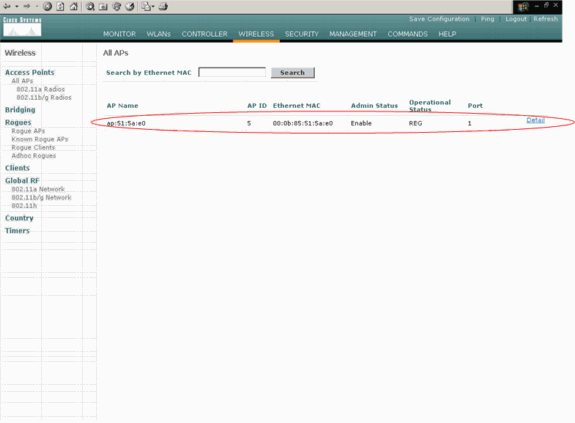
Complete these steps in order to configure the LAP for normal REAP mode:
-
From the WLC GUI, click Wireless.
The All APs window appears. This window lists the APs that are registered to the WLC.
-
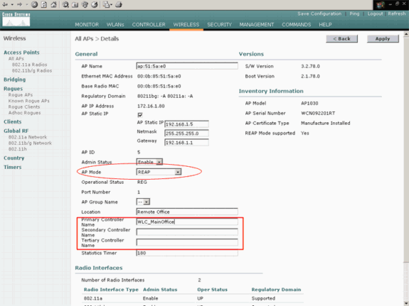
Select the AP that you must configure for REAP mode and click Detail.
The All APs > Detail window for the specific AP appears. In this window, you can configure the various parameters of the AP, which include:
-
AP name
-
IP address (which you can change to static)
-
Admin status
-
Security parameters
-
AP mode
-
List of WLCs to which the AP can connect
-
Other parameters
-
-
Choose REAP from the AP Mode drop-down menu.
This mode is only available on REAP-capable APs.
-
Define the controller names that the APs will use to register and click Apply.
You can define up to three controller names (primary, secondary, and tertiary). The APs search for the controller in the same order that you provide in this window. Because this example uses only one controller, the example defines the controller as the primary controller.
Here is an example:
You have set up the AP for REAP mode, and you can deploy it at the remote site.
Note: In this example window, you can see that the IP address of the AP is changed to static and a static IP address 192.168.1.5 is assigned. This assignment occurs because this is the subnet to be used at the remote office. So you use the IP address from the DHCP server, 172.16.1.80, only during the priming stage. After the AP is registered to the controller, you change the address to a static IP address.
Configure the 2800 Routers to Establish the WAN Link
In order to establish the WAN link, this example uses two 2800 series routers with OSPF to route information between the networks. Here is the configuration of both the routers for the example scenario in this document:
| MainOffice |
|---|
MainOffice#show run Building configuration... Current configuration : 728 bytes ! version 12.2 service timestamps debug uptime service timestamps log uptime no service password-encryption ! hostname MainOffice ! ! ip subnet-zero ! ! ! ! interface Ethernet0 ip address 172.16.1.60 255.255.0.0 !--- This is the interface which acts as the default gateway to the WLC. ! interface Virtual-Template1 no ip address ! interface Serial0 no ip address ! interface Serial1 !--- This is the interface for the WAN link. ip address 10.0.0.1 255.0.0.0 encapsulation ppp !--- This example uses PPP. Use the appropriate !--- encapsulation for the WAN connection. ! router ospf 50 !--- Use OSPF to route data between the different networks. log-adjacency-changes network 10.0.0.0 0.255.255.255 area 0 network 172.16.0.0 0.0.255.255 area 0 ! ! ip classless ip http server ! ! ! line con 0 line aux 0 line vty 0 4 ! end |
| BranchOffice |
|---|
BranchOffice#show run Building configuration... Current configuration : 596 bytes ! version 12.2 service timestamps debug datetime msec service timestamps log datetime msec no service password-encryption ! hostname BranchOffice ! ! ip subnet-zero ! ! ! ! interface Ethernet0 ip address 192.168.1.1 255.255.255.0 !--- This is the interface which acts as the default gateway to the LAP. ! interface Serial0 no ip address ! interface Serial1 !--- This is the interface for the WAN link. ip address 10.0.0.2 255.0.0.0 encapsulation ppp clockrate 56000 ! router ospf 50 !--- Use OSPF to route data between the different networks. log-adjacency-changes network 10.0.0.0 0.255.255.255 area 0 network 192.168.1.0 0.0.0.255 area 0 ! ip classless ip http server ! ! ! ! line con 0 line aux 0 line vty 0 4 login autocommand access enable-timeout 2 ! end |
Deploy the REAP AP at the Remote Site
Now that you have configured WLANs on the WLCs, primed the LAP, and established the WAN link between the main office and the remote office, you are ready to deploy the AP at the remote site.
After you power up the AP at the remote site, the AP looks for the controller in the order that you configured in the priming stage. After the AP finds the controller, the AP registers with the controller. Here is an example. From the WLC, you can see that the AP has joined the controller on port 1:

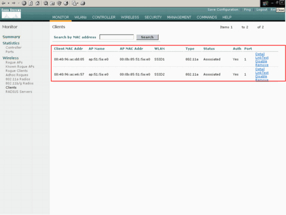
Clients that have the SSID SSID1, and for which WPA-PSK is enabled, associate to the AP on WLAN 1. Clients that have the SSID SSID2, and that have 802.1x authentication enabled, associate to the AP on WLAN 2. Here is an example that shows two clients. One client is connected to WLAN 1, and the other client is connected to WLAN 2:
Verify
Use this section to confirm that your REAP configuration works properly.
Note: Refer to Important Information on Debug Commands before you use debug commands.
Bring down the WAN link. When the WAN link is down, the AP loses connectivity with the WLC. The WLC then deregisters the AP from its list. Here is an example:
(Cisco Controller) >debug lwapp events enable
Wed May 17 15:04:22 2006: Did not receive heartbeat reply from AP 00:0B:85:51:5A:E0
Wed May 17 15:04:22 2006: Max retransmissions reached on AP 00:0B:85:51:5A:E0
(CONFIGURE_COMMAND, 1)
Wed May 17 15:04:22 2006: apfSpamProcessStateChangeInSpamContext: Down LWAPP event for
AP 00:0b:85:51:5a:e0 slot 0
Wed May 17 15:04:22 2006: apfSpamProcessStateChangeInSpamContext: Deregister LWAPP event
for AP 00:0b:85:51:5a:e0 slot 0
Wed May 17 15:04:22 2006: apfSpamProcessStateChangeInSpamContext: Down LWAPP event for
AP 00:0b:85:51:5a:e0 slot 1
Wed May 17 15:04:22 2006: apfSpamProcessStateChangeInSpamContext: Deregister LWAPP event
for AP 00:0b:85:51:5a:e0 slot 1
Wed May 17 15:04:22 2006: spamDeleteLCB: stats timer not initialized for AP
00:0b:85:51:5a:e0
Wed May 17 15:04:22 2006: Received LWAPP Down event for AP 00:0b:85:51:5a:e0 slot 0!
Wed May 17 15:04:22 2006: Deregister LWAPP event for AP 00:0b:85:51:5a:e0 slot 0
Wed May 17 15:04:22 2006: Received LWAPP Down event for AP 00:0b:85:51:5a:e0 slot 1!
Wed May 17 15:04:22 2006: Deregister LWAPP event for AP 00:0b:85:51:5a:e0 slot 1
From the debug lwapp events enable command output, you can see that the WLC deregisters the AP because the WLC did not receive a heartbeat reply from the AP. A heartbeat reply is similar to keepalive messages. The controller tries five consecutive heartbeats, 1 second apart. If the WLC does not receive a reply, the WLC deregisters the AP.
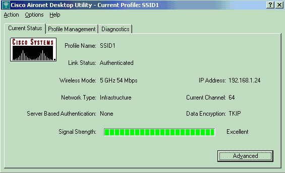
When the AP is in standalone mode, the AP power LED flashes. The clients which associate to the first WLAN (WLAN 1) are still associated to the AP because the clients in the first WLAN are configured for WPA-PSK encryption only. The LAP handles the encryption itself in standalone mode. Here is an example that shows the status (when the WAN link is down) of a client that is connected to WLAN 1 with SSID1 and WPA-PSK:
Note: TKIP is the encryption that is used with WPA-PSK.
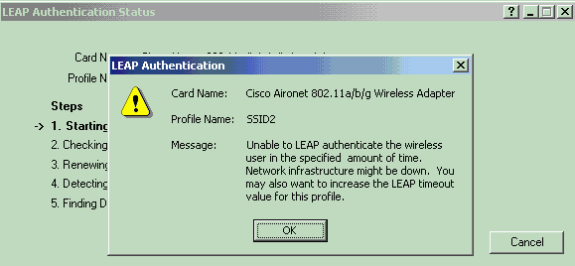
The clients that are connected to WLAN 2 are disconnected because WLAN 2 uses EAP authentication. This disconnection occurs because clients that use EAP authentication need to communicate to the WLC. Here is an example window which shows that the EAP authentication fails when the WAN link is down:
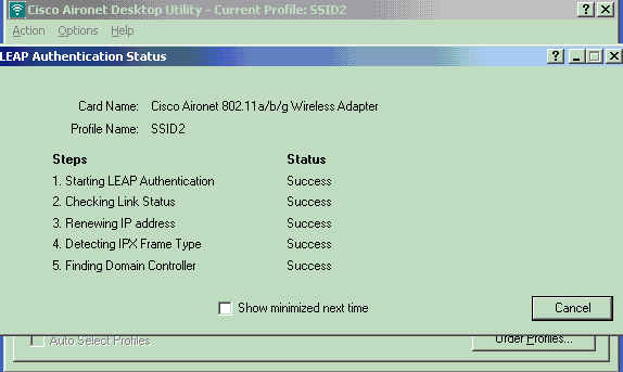
After the WAN link is up, the AP switches back to normal REAP mode and registers with the controller. The client that uses EAP authentication also comes up. Here is an example:
This sample output of the debug lwapp events enable command on the controller shows these results:
(Cisco Controller) >debug lwapp events enable
Wed May 17 15:06:40 2006: Successful transmission of LWAPP Discovery-Response
to AP 00:0b:85:51:5a:e0 on Port 1
Wed May 17 15:06:52 2006: Received LWAPP JOIN REQUEST from AP 00:0b:85:51:5a:e0to
00:0b:85:33:84:a0 on port '1'
Wed May 17 15:06:52 2006: LWAPP Join-Request MTU path from AP 00:0b:85:51:5a:e0is 1500,
remote debug mode is 0
Wed May 17 15:06:52 2006: Successfully added NPU Entry for AP 00:0b:85:51:5a:e0(index 51)
Switch IP: 172.16.1.51, Switch Port: 12223, intIfNum 1, vlanId 0AP IP: 192.168.1.5, AP
Port: 5550, next hop MAC: 00:d0:58:ad:ae:cb
Wed May 17 15:06:52 2006: Successfully transmission of LWAPP Join-Reply to AP
00:0b:85:51:5a:e0
Wed May 17 15:06:52 2006: Register LWAPP event for AP 00:0b:85:51:5a:e0 slot 0
Wed May 17 15:06:52 2006: Register LWAPP event for AP 00:0b:85:51:5a:e0 slot 1
Wed May 17 15:06:54 2006: Received LWAPP CONFIGURE REQUEST from AP 00:0b:85:51:5a:e0 to
00:0b:85:33:84:a0
Wed May 17 15:06:54 2006: Updating IP info for AP 00:0b:85:51:5a:e0 -- static 1,
192.168.1.5/255.255.255.0, gtw 192.168.1.1
Troubleshoot
Use this section to troubleshoot your configuration.
Troubleshooting Commands
You can use these debug commands to troubleshoot the configuration.
Note: Refer to Important Information on Debug Commands before you use debug commands.
-
debug lwapp events enable—Displays the sequence of events that occur between the LAP and the WLC.
-
debug lwapp errors enable—Displays the errors that occur in the LWAPP communication.
-
debug lwapp packet enable—Displays the debug of an LWAPP packet trace.
-
debug mac addr—Enables MAC debugging for the client that you specify.
Related Information
- REAP Deployment Guide at the Branch Office
- EAP Authentication with WLAN Controllers (WLC) Configuration Example
- Wireless LAN Controller and Lightweight Access Point Basic Configuration Example
- WLAN Controller Failover for Lightweight Access Points Configuration Example
- Wireless Support Page
- Technical Support & Documentation - Cisco Systems
Revision History
| Revision | Publish Date | Comments |
|---|---|---|
1.0 |
17-May-2006 |
Initial Release |
Contact Cisco
- Open a Support Case

- (Requires a Cisco Service Contract)


 Feedback