Configure AireOS Wireless LAN Controller Web Authentication
Available Languages
Download Options
Bias-Free Language
The documentation set for this product strives to use bias-free language. For the purposes of this documentation set, bias-free is defined as language that does not imply discrimination based on age, disability, gender, racial identity, ethnic identity, sexual orientation, socioeconomic status, and intersectionality. Exceptions may be present in the documentation due to language that is hardcoded in the user interfaces of the product software, language used based on RFP documentation, or language that is used by a referenced third-party product. Learn more about how Cisco is using Inclusive Language.
Contents
Introduction
This document describes how to configure a Cisco 4400 Series Wireless LAN (WLAN) Controller (WLC) to support an Internal web authentication.
Prerequisites
Requirements
Cisco recommends that you have an initial configuration on 4400 WLC.
Components Used
The information in this document is based on these software and hardware versions:
-
A 4400 series WLC that runs version 7.0.116.0
-
Cisco Secure Access Control Server (ACS) version 4.2 installed on a Microsoft® Windows 2003 Server
-
Cisco Aironet 1131AG Series Light Weight Access Point
-
Cisco Aironet 802.11 a/b/g CardBus Wireless Adapter that runs version 4.0
The information in this document was created from the devices in a specific lab environment. All of the devices used in this document started with a cleared (default) configuration. If your network is live, ensure that you understand the potential impact of any command.
Conventions
Refer to Use Format Conventions for Technical Tips and Other Content for more information on document conventions.
Web Authentication
Web authentication is a Layer 3 security feature that causes the controller to not allow IP traffic (except DHCP and DNS-related packets) from a particular client until that client has correctly supplied a valid username and password. It is a simple Authentication method without the need for a supplicant or client utility. Web authentication is typically used by customers who want to deploy a guest-access network. Typical deployments can include "hot spot" locations like those provided by T-Mobile® or Starbucks®.
Keep in mind that web authentication does not provide data encryption. Web authentication is used as simple guest access for either a hot spot or campus atmosphere where the only concern is the connectivity.
Web authentication can be performed with:
-
Default log in window on the WLC
-
Modified version of the default log in window on the WLC
-
A customized log in window that you configure on an external web server (External web authentication)
-
A customized log in window that you download to the controller
In this document, the Wireless LAN Controller for Internal web authentication is configured.
Web Authentication Process
This is what occurs when a user connects to a WLAN configured for web authentication:
-
The user opens a web browser and enters a URL, for example, http://www.cisco.com. The client sends out a DNS request for this URL to get the IP for the destination. The WLC bypasses the DNS request to the DNS server and the DNS server responds back with a DNS reply, which contains the IP address of the destination www.cisco.com. This, in turn, is forwarded to the wireless clients.
-
The client then tries to open a TCP connection with the destination IP address. It sends out a TCP SYN packet destined to the IP address of www.cisco.com.
-
The WLC has rules configured for the client and hence can act as a proxy for www.cisco.com. It sends back a TCP SYN-ACK packet to the client with source as the IP address of www.cisco.com. The client sends back a TCP ACK packet in order to complete the three way TCP handshake and the TCP connection is fully established.
-
The client sends an HTTP GET packet destined to www.cisco.com. The WLC intercepts this packet and sends it for redirection handling. The HTTP application gateway prepares a HTML body and sends it back as the reply to the HTTP GET requested by the client. This HTML makes the client go to the default webpage URL of the WLC, for example, http://<Virtual-Server-IP>/login.html.
-
The client closes the TCP connection with the IP address, for example, www.cisco.com.
-
Now the client wants to go to http://10.1.1.1/login.html. Therefore, the client tries to open a TCP connection with the virtual IP address of the WLC. It sends a TCP SYN packet for 10.1.1.1 to the WLC.
-
The WLC responds back with a TCP SYN-ACK and the client sends back a TCP ACK to the WLC in order to complete the handshake.
-
The client sends a HTTP GET for /login.html destined to 10.1.1.1 in order to request for the log in page.
-
This request is allowed up to the Web Server of the WLC, and the server responds back with the default log in page. The client receives the log in page on the browser window where the user can go ahead and log in.
For an explanation on the Web Authentication process, refer to Web Authentication on Cisco Wireless LAN Controllers (WLCs).
Network Setup
This document uses this network setup:
 Network Setup
Configure the Controller for Web Authentication
In this document, a WLAN is configured for web authentication and mapped to a dedicated VLAN. These are the steps involved to configure a WLAN for web authentication:
This section focuses on how to configure the controller for web authentication.
These are the IP addresses used in this document:
-
The IP address of the WLC is 10.77.244.204.
-
The IP address of the ACS server is 10.77.244.196.
Create a VLAN Interface
Complete these steps:
-
From the Wireless LAN controller GUI, choose Controller from the menu at the top, choose Interfaces from the menu on the left, and click New on the upper right side of the window to create a new dynamic interface.
The Interfaces > New window appears. This example uses Interface Name vlan90 with a VLAN ID of 90:
 Interface > New Window Opens
 -
Click Apply in order to create the VLAN interface.
The Interfaces > Edit window appears that asks you to fill interface specific information.
-
This document uses these parameters:
-
IP Address—10.10.10.2
-
Netmask—255.255.255.0 (24 bits)
-
Gateway—10.10.10.1
-
Port Number—2
-
Primary DHCP Server—10.77.244.204
Note: This parameter must be the IP address of your RADIUS or DHCP server. In this example, the management address of the WLC is used as the DHCP server because the Internal DHCP scope is configured on the WLC.
-
Secondary DHCP Server—0.0.0.0
Note: The example does not have a secondary DHCP server, so uses 0.0.0.0. If your configuration has a secondary DHCP server, add the server IP address in this field.
-
ACL Name—None
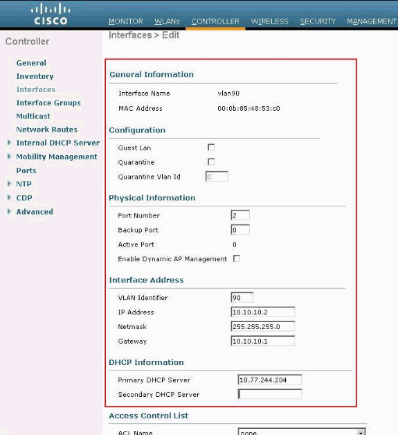 General Information in the Interfaces > Edit Window
 -
-
Click Apply to save the changes.
Configure WLC for Internal Web Authentication
The next step is to configure the WLC for the Internal web authentication. Internal web authentication is the default web authentication type on WLCs. If this parameter has not been changed, no configuration is required to enable Internal web authentication. If the web authentication parameter was changed previously, complete these steps to configure the WLC for Internal web authentication:
-
From the controller GUI, choose Security > Web Auth >Web Login Page to access the Web Login Page.
-
From the Web Authentication Type drop-down box, choose Internal Web Authentication.
-
In the Redirect URL after login field, enter the URL of the page to which the end user is redirected to after successful authentication.
 Redirect URL after Login
Note: In WLC versions 5.0 and later, the log out page for web-authentication can also be customized.
Add a WLAN Instance
Now that Internal web authentication has been enabled and there is a VLAN interface dedicated for web authentication, you must provide a new WLAN/SSID in order to support the web authentication users.
Complete these steps in order to create a new WLAN/SSID:
-
From the WLC GUI, click WLAN in the menu at the top, and click New on the upper right side.
Choose WLAN as the Type. Choose a profile name and WLAN SSID for Web authentication. This example usesGuestfor both the Profile Name and WLAN SSID.
 Profile Name and WLAN SSID
 -
Click Apply.
A new WLANs > Edit window appears.
 WLANs > Edit Window Appears
 -
Check the status box of the WLAN in order to enable the WLAN. From the Interface menu, select the name of the VLAN interface that you created previously. In this example, the Interface Name is vlan90.
Note: Leave the default value for other parameters on this screen.
-
Click the Security tab.
Complete these steps in order to configure web authentication:
-
Click the Layer 2 tab and set the security to None .
Note: You cannot configure web pass through as Layer 3 security with 802.1x or WPA/WPA2 as Layer 2 Security for a WLAN. Refer to Wireless LAN Controller Layer 2 Layer 3 Security Compatibility Matrix for more information on the Wireless LAN Controller Layer 2 and Layer 3 security compatibility
-
Click the Layer 3 tab. Check the Web Policy box and choose the Authentication option, as shown here:
 Layer 3 Tab and Check the Web Policy Box
 -
Click Apply in order to save the WLAN.
-
You are returned to the WLAN summary window. Make sure that the Web-Auth is enabled under the Security Policies column of the WLAN table for the SSID Guest.
-
Three Ways to Authenticate Users in Web Authentication
There are three ways to authenticate users when you use web authentication. Local authentication allows you to authenticate the user in the Cisco WLC. You can also use an external RADIUS server or a LDAP server as a backend database in order to authenticate the users.
This document provides an example configuration for all three methods.
Local Authentication
The user database for the guest users are stored on the WLC local database. Users are authenticated by the WLC against this database:
-
From the WLC GUI, choose Security.
-
Click Local Net Users from the AAA menu on the left.
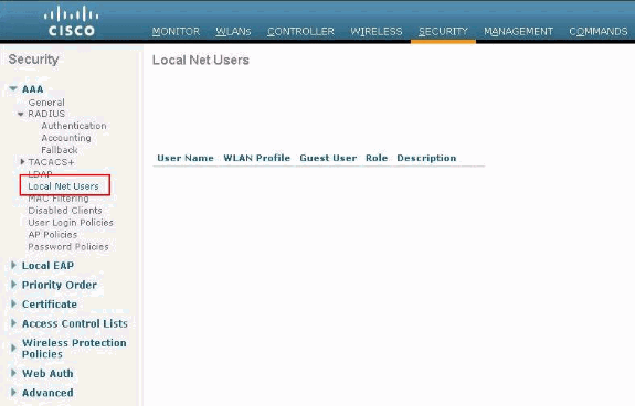 Click Local Net User from Left-hand Menu
 -
Click New to create a new user.
A new window displays that asks for username and password information.
-
Enter a username and password in order to create a new user, then confirm the password that you want to use.
This example creates the user named User1.
-
Add a description.
This example uses Guest User1.
-
Click Apply to save the new user configuration.
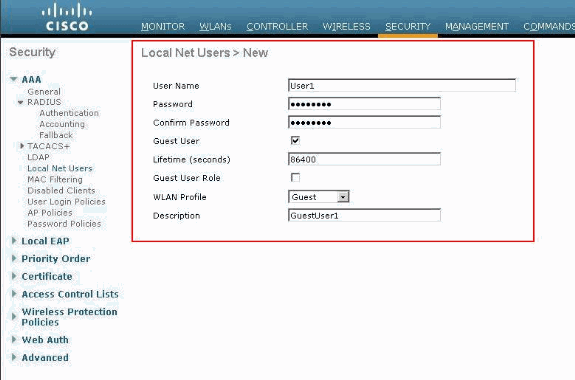 Apply to Save the New User Configuration
 Local Net Users
7. Repeat steps 3-6 to add more users to the database.
RADIUS Server for Web Authentication
This document uses a wireless ACS on Windows 2003 Server as the RADIUS server. You can use any available RADIUS server that you currently deploy in your network.
Note: ACS can be set up on either Windows NT or Windows 2000 Server. In order to download ACS from Cisco.com, refer to Software Center (Downloads) - Cisco Secure Software. You need a Cisco web account in order to download the software.
Note: Only registered Cisco users have access to internal Cisco tools and information.
The Set Up ACS section shows you how to configure ACS for RADIUS. You must have a fully functional network with a Domain Name System (DNS) and a RADIUS server.
Set Up ACS
In this section, you are presented with the information to set up ACS for RADIUS.
Set up ACS on your server and then complete these steps in order to create a user for authentication:
-
When ACS asks if you want to open ACS in a browser window to configure, click Yes.
Note: After you set up ACS, you also have an icon on your desktop.
-
In the menu on the left, click User Setup.
This action takes you to User Setup screen as shown here:
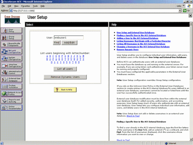 User Setup Screen
 -
Enter the user that you want to use for web authentication, and click Add/Edit.
After the user is created, a second window opens as shown here:
 After User is Created, Second Window Opens
 -
Ensure that the Account Disabled Box at the top is not checked.
-
Choose ACS Internal Database for the Password Authentication option.
-
Enter the password. Admin has an option to configure PAP/CHAP or MD5-CHAP authentication and add a user in the ACS internal database. PAP is the default authentication type for web-auth users on controllers. Admin has the flexibility to change the authentication method to chap/md5-chap with this CLI command:
config custom-web radiusauth <auth method>
7. Click Submit.
Enter Your RADIUS Server Information into the Cisco WLC
Complete these steps:
-
Click Security in the menu at the top.
-
Click RADIUS Authentication in the menu on the left.
-
Click New and enter the IP address of your ACS/RADIUS server. In this example, the IP address of the ACS server is 10.77.244.196.
-
Enter the shared secret for the RADIUS server. Make sure that this secret key is the same as the one you entered in the RADIUS server for the WLC.
-
Leave the Port number at the default, 1812.
-
Ensure that the Server Status option is Enabled.
-
Check the Network User Enable box so that this RADIUS Server is used to authenticate your wireless network users.
-
ClickApply.
 Network User Enable Box
Make sure that the Network User box is checked, and Admin Status is Enabled.
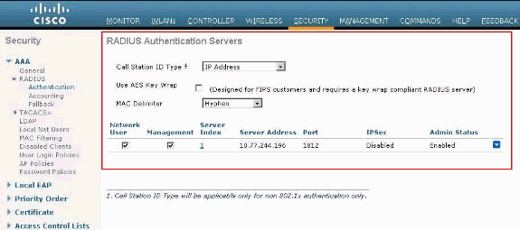 Check Network User Box and Enable Admin Status
Configure WLAN with RADIUS Server
Now that the RADIUS server is configured on the WLC, you need to configure the WLAN to use this RADIUS server for web authentication. Complete these steps in order to configure WLAN with the RADIUS server.
-
Open your WLC browser and click WLANs. This displays the list of WLANs configured on the WLC. Click the WLAN Guest which was created for web authentication.
-
On the WLANs > Edit page click the Security Tab. Click the AAA Servers tab under Security. Then, choose the RADIUS server which is 10.77.244.196 in this example:
 Click Security Tab and then the AAA Servers Tab
 -
Click Apply.
Verify ACS
When you set up the ACS, remember to download all the current patches and latest code. This can solve imminent issues. In case you use RADIUS Authentication make sure that your WLC is listed as one of the AAA Clients. Click the Network Configuration menu on the left hand side to check this. Click the AAA client, then verify the password and the authentication type configured.
 WLC is Listed as an AAA Client
When you choose User Setup, verify again that your users actually exist. Click List all users. A window as shown appears. Make sure the user that has been created exists in the list.
 List All Users
LDAP Server
This section explains how to configure a Lightweight Directory Access Protocol (LDAP) server as a backend database, similar to a RADIUS or local user database. An LDAP backend database allows the controller to query an LDAP server for the credentials (username and password) of a particular user. These credentials are then used to authenticate the user.
Complete these steps to configure LDAP with the controller GUI:
-
Click Security > AAA > LDAP in order to open the LDAP Servers.
This page lists any LDAP servers that have already been configured.
-
If you want to delete a current LDAP server, move your cursor over the blue drop-down arrow for that server and choose Remove.
-
If you want to make sure that the controller can reach a particular server, hover your cursor over the blue drop-down arrow for that server and choose Ping.
-
-
Perform one of these options:
-
To edit a current LDAP server, click the index number for that server. The LDAP Servers > Edit page appears.
-
To add an LDAP server, click New. The LDAP Servers > New page appears.
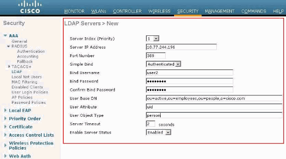 Add LDAP Server
-
-
If you add a new server, choose a number from the Server Index (Priority) drop-down box to specify the priority order of this server in relation to any other configured LDAP servers. You can configure up to seventeen servers. If the controller cannot reach the first server, then it tries the second one from the list and so on.
-
If you add a new server, enter the IP address of the LDAP server in the Server IP Address field.
-
If you add a new server, enter the LDAP server TCP port number in the Port Number field. The valid range is 1 to 65535, and the default value is 389.
-
Check the Enable Server Status check box to enable this LDAP server or uncheck it to disable it. The default value is disabled.
-
From the Simple Bind drop-down box, choose Anonymous or Authenticated to specify the local authentication bind method for the LDAP server. The Anonymous method allows anonymous access to the LDAP server, whereas the Authenticated method requires that a username and password be entered to secure access. The default value is Anonymous.
-
If you chose Authenticated in Step 7, complete these steps:
-
In the Bind Username field, enter a username to be used for local authentication to the LDAP server.
-
In the Bind Password and Confirm Bind Password fields, enter a password to be used for local authentication to the LDAP server.
-
-
In the User Base DN field, enter the distinguished name (DN) of the subtree in the LDAP server that contains a list of all the users. For example, ou=organizational unit, .ou=next organizational unit, and o=corporation.example. If the tree that contains users is the base DN, type o=corporation.example or dc=corporation, dc=com.
-
In the User Attribute field, enter the name of the attribute in the user record that contains the username. You can obtain this attribute from your directory server.
-
In the User Object Type field, enter the value of the LDAP objectType attribute that identifies the record as a user. Often, user records have several values for the objectType attribute, some of which are unique to the user and some of which are shared with other object types.
-
In the Server Timeout field, enter the number of seconds between re-transmissions. The valid range is 2 to 30 seconds, and the default value is 2 seconds.
-
Click Apply to commit your changes.
-
Click Save Configuration to save your changes.
-
Complete these steps if you wish to assign specific LDAP servers to a WLAN:
-
ClickWLANsto open the WLANs page.
-
Click the ID number of the desired WLAN.
-
When the WLANs > Edit page appears, click the Security>AAA Servers tabs to open the WLANs > Edit (Security > AAA Servers) page.
 Click Security > AAA Servers Tabs
 -
From the LDAP Servers drop-down boxes, choose the LDAP server(s) that you want to use with this WLAN. You can choose up to three LDAP servers, which are tried in priority order.
-
Click Apply to commit your changes.
-
Click Save Configuration to save your changes.
-
Configure Your WLAN Client to Use Web Authentication
Once the WLC is configured, the client must be configured appropriately for web authentication. In this section, you are presented with the information to configure your Windows system for web authentication.
Client Configuration
The Microsoft wireless client configuration remains mostly unchanged for this subscriber. You only need to add the appropriate WLAN/SSID configuration information. Complete these steps:
-
From the Windows Start menu, choose Settings > Control Panel> Network and Internet Connections.
-
Click the Network Connections icon.
-
Right-click the LAN Connection icon and choose Disable.
-
Right-click the Wireless Connection icon and choose Enable.
-
Right-click the Wireless Connection icon again and choose Properties.
-
From the Wireless Network Connection Properties window, click the Wireless Networks tab.
-
Under the preferred networks, area click Add in order to configure the Web authentication SSID.
-
Under the Association tab, enter the Network Name (WLAN/SSID) value that you want to use for web authentication.
 Under Association Tab Enter the Network Name
Note: The Data Encryption is Wired Equivalent Privacy (WEP) by default. Disable the Data Encryption in order for web authentication to work.
-
Click OK at the bottom of the window in order to save the configuration.
When you communicate with the WLAN, you see a beacon icon in the Preferred Network box.
This shows a successful wireless connection to web authentication. The WLC has provided your wireless Windows client with an IP address.
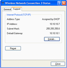 WLC Provided IP Address
Note: If your wireless client is also a VPN end point and you have web authentication configured as a security feature for WLAN, then the VPN tunnel is not established until you go through the web authentication process explained here. In order to establish a VPN tunnel, the client must first go through the process of web authentication with success. Only then does a VPN tunnel succeed.
Note: After a successful log in, if the wireless clients are idle and do not communicate with any of the other devices, the client is de-authenticated after an idle timeout period. The timeout period is 300 seconds by default and can be changed with this CLI command: config network usertimeout <seconds>. When this occurs, client entry is removed from the controller. If the client associates again, it can move back to a Webauth_Reqd state.
Note: If clients are active after successful log in, they can get de-authenticated and the entry can still be removed from the controller after the session timeout period configured on that WLAN (for example,1800 seconds by default and can be changed with this CLI command: config wlan session-timeout <WLAN ID> <seconds> ). When this occurs, client entry is removed from the controller. If the client associates again, it can move back in a Webauth_Reqd state.
If clients are in Webauth_Reqd state, no matter if they are active or idle, the clients can get deauthenticated after a web-auth required timeout period (for example, 300 seconds and this time is non-user configurable). All traffic from the client (allowed via Pre-Auth ACL) is disrupted. If the client associates again, it moves back to the Webauth_Reqd state.
Client Log In
Complete these steps:
-
Open a browser window and enter any URL or IP Address. This brings the web authentication page to the client.
If the controller runs any release earlier than 3.0, the user has to enter https://10.1.1.1/login.html to bring up the web authentication page.
A security alert window displays.
-
Click Yes to proceed.
-
When the Login window appears, enter the username and password of the Local Net User that you created.
 Login Window
If your log in is successful, you see two browser windows. The larger window indicates successful log in and you can this window to browse the internet. Use the smaller window in order to log out when your use of the guest network is complete.
The previous image shows a successful redirect for web authentication.
The next image shows the Login Successful window, which displays when authentication has occurred.
 Login Successful!
Cisco 4404/WiSM controllers can support 125 simultaneous Web Auth Users log ins and scale up to 5000 web auth clients.
Cisco 5500 controllers can support 150 simultaneous Web Auth Users log ins.
Troubleshoot Web Authentication
Troubleshoot ACS
If you have issues with password authentication, click Reports and Activity on the lower left side of the ACS in order to open all available reports. After you open the reports window, you have the option to open RADIUS Accounting, Failed Attempts for log in, Passed Authentications, Logged-in Users, and other reports. These reports are .csv files, and you can open the files locally on your machine. The reports help uncover issues with authentication, such as incorrect user name and/or password. ACS also comes with online documentation. If you are not connected to a live network and have not defined the service port, ACS uses the IP address of your Ethernet port for your service port. If your network is not connected, you most likely end up with the Windows 169.254.x.x default IP address.
 Reports and Activity Window
Note: If you type in any external URL, the WLC automatically connects you to the internal web authentication page. If the automatic connection does not work, you can enter the management IP address of the WLC in the URL bar in order to troubleshoot. Look at the top of the browser for the message that says to redirect for web authentication.
Refer to Troubleshoot Web Authentication on a Wireless LAN Controller (WLC )for more information on how to troubleshoot web authentication.
Web Auth with IPv6 Bridging
In order to configure a WLAN for IPv6 bridging, from the controller GUI, navigate to WLANs. Then, select the desired WLAN and choose Advanced from the WLANs >Edit page.
Select the IPv6 Enable check box if you want to enable clients that connect to this WLAN to accept IPv6 packets. Otherwise, leave the check box unselected, which is the default value. If you disable (or uncheck) the IPv6 check box, IPv6 is only allowed after authentication. Enabling IPv6 means that the controller can pass IPv6 traffic without client authentication.
 Select the Desired WLAN and Choose Advanced
Related Information
- Troubleshoot Web Authentication on a Wireless LAN Controller (WLC)
- Cisco Wireless LAN
- Wired Guest Access with Cisco WLAN Controllers Configuration Example
- Cisco Wireless LAN Controller Retirement Notice
- Authentication of Wireless LAN Controller Lobby Administrator via RADIUS Server
- Cisco Technical Support & Downloads
Revision History
| Revision | Publish Date | Comments |
|---|---|---|
1.0 |
19-Jul-2011 |
Initial Release |
Contributed by Cisco Engineers
Contact Cisco
- Open a Support Case

- (Requires a Cisco Service Contract)
 Feedback