Troubleshoot Common Problems with Wireless Bridged Networks
Available Languages
Contents
Introduction
This document provides information to help identify and troubleshoot common problems in a wireless bridged network. Common problems fall into three categories: basic operational failure, connectivity failure, and poor throughput.
Prerequisites
Requirements
There are no specific requirements for this document.
Components Used
Cisco Aironet equipment operates best when all components are loaded with the latest versions of software. Upgrade to the latest versions of the software early in the troubleshooting process.
You can download the latest software and drivers at the Wireless Software Center.
The information in this document was created from the devices in a specific lab environment. All of the devices used in this document started with a cleared (default) configuration. If your network is live, make sure that you understand the potential impact of any command.
Note: The information in this document applies to all platforms of wireless bridges unless it is mentioned specifically.
Conventions
Refer to Cisco Technical Tips Conventions for more information on document conventions.
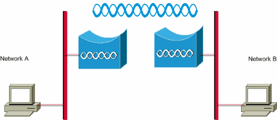
Network Diagram
This document uses this network topology:

Basic Operational Failure
These are the symptoms of basic operational failure:
-
Negative or unidentifiable LED patterns
Refer to Bridge Normal Mode LED Indications for more information on the regular LED patterns on wireless bridges.
-
Error messages across the console
-
Constant rebooting
These problems are usually catastrophic, and frequently require that you replace the bridge. Contact Cisco Technical Support with specific details about the operational failure. Have the serial number of the bridge and a ship-to address available in case the Cisco Technical Support engineer determines that hardware replacement is required.
You can open a service request online through the TAC Service Request Tool (registered customers only) for equipment under warranty or under a support contract.
Connectivity Failure
Lack of connectivity means that traffic cannot pass from site to site. You can loose connectivity after a long period of successful operation, or at any time after the units are physically deployed. In either situation, troubleshooting is the same. Issue the ping utility from a command line of the operating system from your computer in order to isolate the point where connectivity is lost. Do not immediately try to make a big step from end to end. Instead, take smaller steps to determine where connectivity is lost. These steps, used in order, can help to isolate the loss of connectivity.
-
Ping yourself (the PC).
A successful reply indicates that the IP stack on the PC works correctly. Complete these steps if you cannot ping yourself:
-
Check the cable between your PC and the hub or switch to which it is connected.
-
Check the IP properties of your network connection.
-
Check the drivers and any accompanying utilities for your network card.
-
Contact the manufacturer of your network card or operating system as needed.
-
-
Ping the local bridge at your site.
A successful reply indicates that the LAN local to you works correctly. Complete these steps if you cannot ping your local bridge:
-
Check the cabling between your bridge and the hub or switch to which it is connected.
-
If the Ethernet interface on the bridge or the port on your hub or switch is set to auto speed or auto-duplex, specify a speed and duplex setting instead. Configure it the same on both devices, then try to ping the local bridge at your site again.
-
-
Ping the remote bridge at the far site.
A successful reply indicates that the radio frequency connection between the two bridges works correctly. Complete these steps if you cannot ping the remote bridge:
-
Verify that the two bridges are associated.
-
Verify that only one bridge has the root parameter turned on.
In a bridged network, only one bridge at a time can be the root bridge.
-
Verify that the Service Set Identifier (SSID) is the same in both bridges.
-
If Wireless Encryption Protocol (WEP) is enabled, disable it temporarily until you can establish connectivity, then re-enable it once you have resolved other problems. This ensures that the WEP key mismatch is on the root and the non-root bridge is not the root cause of the problem.
Note: Refer to Troubleshooting Connectivity in a Wireless LAN Network for more information on troubleshooting connectivity in a wireless network. The Bridge section of this document is helpful at this point.
Also, refer to Wireless Bridges Point-to-Point Link Configuration Example for additional information.
If you can ping, but not with 100 percent accuracy, or if the ping times are excessively long, see the Poor Throughput section of this document.
-
-
Ping your final target, the remote PC.
A successful reply indicates that the remote LAN works correctly. Complete these steps if you cannot ping the server or the device you target:
-
Check the network card, hub or switch, and cabling at the far side.
-
Check the IP properties of the network connection on that device.
-
Try to re-run these basic tests from that device in order to locate the loss of connectivity.
-
Data Rate Mismatch
Wireless bridges can run into connectivity issues if you configure the bridges with sub-optimal or incorrect data rate settings. If you configure the data rates incorrectly on wireless bridges, the bridges fail to communicate.
A typical example is a scenario where one of the bridges is configured for a fixed data rate, such as 11 Mbps, and the other bridge is configured with a data rate of 5 Mbps. Normally, the bridge attempts to transmit at the highest data rate set to basic, also called require, on the browser-based interface. In case of obstacles or interference, the bridge steps down to the highest rate that allows data transmission. If one of the two bridges has a data rate of 11 Mbps set, and the other is set to use any rate, the two units communicate at 11 Mbps. However, in case of some impairment in the communication that requires the units to fall back to a lower data rate, the unit set for 11 Mbps cannot fall back. Therefore, communications fail.
This is one of the most common problems that relates to data rates. The workaround is to use optimized data rate settings on the two wireless bridges.
Intermittent Connectivity Issues in Wireless Bridges
There are several factors that can result into intermittent connectivity issues. These are some of the common factors:
-
Radio Frequency Interference (RFI)
-
Fresnel Zone and Line of Sight (LOS) issues
-
Problems with Antenna Alignment
-
Clear Channel Assessment (CCA) Parameter
-
Other issues that degrade the performance of wireless bridges
Refer to Intermittent Connectivity Issues in Wireless Bridges for more information about these factors.
Poor Throughput
Problems with bridge performance are the most difficult to troubleshoot because there are so many variables involved. In the case of wireless products, the majority of variables are literally invisible. Bridges have tools built into their software that can help to accurately determine the cause of symptoms of poor throughput, but they might not be able to solve the underlying problem. As a basic approach to troubleshoot this problem, you can increase the transmit power on the non-root bridge. Also, if the distance between the root and non-root bridge is less than 1km, you can set the distance on the root bridge to 1. Therefore, an increased throughput can be obtained.
Remember that the IEEE 802.11b protocol specifies 11 megabits per second, half-duplex, wireless communications. Set your throughput expectations accordingly.
Software
The first step to troubleshoot any problem is to check the version of the software on the bridge.
Use a Telnet session to log into the bridge and issue the show version EXEC command in order to find the version of Cisco IOS® software that runs on your bridge. This example shows command output from a bridge that runs Cisco IOS Release 12.2(13)JA2:
bridge> show version
Cisco Internetwork Operating System Software IOS (tm) C1410 Software (C1410-K9W7-M), Version 12.2(13)JA2 Copyright (c) 1986-2003 by Cisco Systems, Inc.
You can also find the software version on the System Software Version page in the web-browser interface of the bridge.
Start at the Wireless Software Center and choose the model of bridge with which you work. Compare your current version with the highest numbered version of bridge software listed. If you do not run that latest version, upgrade to the latest version in order to start to resolve your throughput issue. Refer to Managing Firmware and Configurations for more information on how to upgrade bridge firmware.
Use Statistical Tools
Bridge software provides tools to show you the types of problems and where the bridge encounters the problems. Two of the most helpful tools are the Throughput Statistics and the Error Statistics windows. In the entire wireless network, there are at least two bridges involved, and it is important to look at statistics from both sides (wired and wireless) of all bridges when you try to isolate a problem. Statistics are only relevant over time, and only when you have some benchmark for comparison. Comparing statistics from two associated bridges clearly shows if the problem is on one side or both.
Throughput Statistics
You need to look at both sets of Throughput Statistics in order to begin. Complete these steps:
-
Navigate to the Statistics page.
This varies and depends on the bridge model.
This document explains the procedure to get to the Statistics page on a 340 Series Bridge that runs VxWorks operating system.
-
Choose Statistics from the Main menu once the connection is established to the bridge.
The Statistics menu provides a broad array of information about the performance of the bridge.
-
Complete the procedure from Viewing Statistics in order to get to the Throughput Statistics page.
-
Clear the statistics on both bridges at the same time so the time factor of the statistics is similar.
Note: Press C (as provided at the bottom of the Throughput Statistics page) in order to clear the Throughput Statistics.
-
Clear and review the statistics several times over the course of a day, or several days, in order to recognize and understand the individual traffic patterns in a given network.
The traffic pattern flows in this sequence:
-
In the Ethernet side of bridge A
-
Out the radio side of bridge A
-
In the radio side of bridge B
-
Out the Ethernet side of bridge B
-
-
Verify that the radio of one bridge successfully transmits all the packets it receives from its Ethernet.

For example, if the Bridge Receive packet count is 1000, verify that the Radio Transmit packet count is somewhat close to 1000.
Note: If the bridge is connected to a hub, the two values might not be close because the hub is a broadcast device and sends the bridge all of the traffic that it receives. However, if the bridge is connected to a switch, the two values should be approximately equal.
-
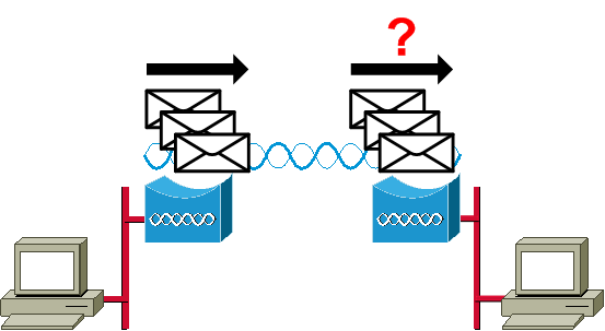
Compare the Radio Transmit packet count on bridge A to the Radio Receive packet count on bridge B.

If the transmit count of bridge A is higher than the receive count of bridge B, then packets are lost over the radio link. This loss is likely caused by one of these problems:
-
The signal is not strong enough for the packets to make it to the far side.
-
The packets are destroyed by some outside interference.
If the receive count of bridge B is higher than the transmit count of bridge A, then additional signals are received. The bridge interprets these as packets. This interference is likely caused by one of these problems:
-
A nearby 2.4 GHz device, such as 2.4 GHz cordless phone, transmits on the same frequency.
-
A nearby microwave oven that leaks sends signals on the same frequency.
-
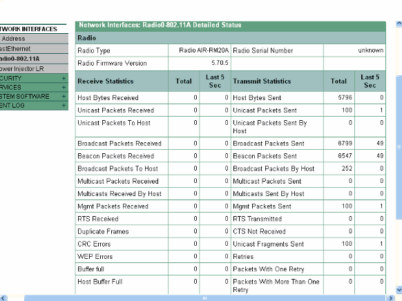
Note: The Statistics page on a 1400 Series Bridge that runs Cisco IOS looks similar to this diagram:

Error Statistics
Refer to Error and Event Messages for more information on the definitions and implications of each type of error on the Error Statistics report. This document is based on the 1400 Series Bridge.
Error Statistics on the Cisco Aironet 340 Series Bridge
While the wired Ethernet side can be full-duplex, the radio side is not. Therefore, when the radio has a packet to transmit, it does not do so while another radio transmits on the same channel or frequency. When this situation occurs, the Holdoffs Statistic counter-increments. When the bridge continues to receive packets in the Ethernet interface, but is unable to transmit them over the radio interface due to holdoffs, the buffers designed to hold those outbound packets fill very quickly. This depends on traffic flow and volume. When those buffers overflow, the excess packets are discarded, and the Queue Full Discards Statistic counter-increments. You might see messages displayed on the console of the bridge or in the error log.
When the radio of a bridge transmits a packet, the receiving bridge must send an ACK back to the transmitting bridge so that the transmitting bridge can move on to the next packet in its transmit queue. If the transmitting bridge does not receive that ACK, it transmits that same packet again until it receives an ACK from the receiving bridge. When a bridge transmits the same packet more than once, the Retries Statistic counter-increments. You can assume one of these situations is true:
-
The receiving bridge did not send the ACK.
-
The ACK is sent, but is not received by the transmitting bridge. Therefore, the transmitter had to resend the packet.
All of these statistics indicate a problem with successful transmission over the radio link and do not indicate a failure of the physical hardware.
Other Basic Troubleshooting Information with the Wireless Bridge
This section provides information to troubleshoot basic problems with the wireless bridge.
Refer to Configuring WEP and WEP Features if the problem is due to misconfiguration and authentication must be reconfigured.
Mismatched basic settings are the most common causes of lost wireless connectivity. If the bridge does not associate with a remote bridge, check these areas.
-
SSID—All bridges must use the same SSID in order to associate. Verify that the SSID value shown on the Express Setup page is the same for all bridges. Also, verify that the bridges are configured for the proper network role. Only one bridge can be configured as the root bridge.
-
Security Settings —Remote bridges that attempt to authenticate to your bridge must use the same security options configured in the bridge. These options include:
-
WEP
-
Extensible Authentication Protocol (EAP)
-
Lightweight Extensible Authentication Protocol (LEAP)
-
MAC address authentication
-
Message Integrity Check (MIC)
-
WEP key hashing
-
802.1X protocol versions
If a non-root bridge is unable to authenticate to your root bridge, verify that the security settings are the same as your bridge settings.
-
Refer to Configuring Authentication Types for more information on how to configure the various authentication types on a 1400 Series Bridge.
Refer to Configuring Authentication Types for more information on how to configure the various authentication types on a 1300 Series Bridge.
Reset to the Default Configuration
If you forget the password that allows you to configure the bridge, you must completely reset the configuration. You can use the MODE button or the web-browser interface to reset the configuration to factory defaults.
The Resetting to the Default Configuration section of the Troubleshooting 1400 Series Bridge provides more information about the reset procedure.
Manage a Firmware Failure/Corruption
There are chances that the Firmware in your bridge might fail to load or be corrupted. In such cases, you should be in a position to fix this issue. You must use the web-browser interface or use the MODE button in order to reload the complete bridge image file. You can use the browser interface if the bridge firmware is still fully operational and if you want to upgrade the firmware image. You can use the MODE button when the bridge has a corrupt firmware image.
The Reloading the Bridge Image section of the Troubleshooting 1400 Series Bridge provides information about this procedure.
Telnet Session Hangs or Does Not Start During Heavy Traffic
When the bridge transmits and receives heavy traffic, sometimes you cannot start a Telnet session, and the Telnet sessions that exist freeze or hang. However, this behavior is expected because the bridge gives top priority to data traffic and a lower priority to Telnet traffic.
Bridge Is Unable to Detect Simultaneous Image Downloads
If you attempt to load software images into the bridge from both a Telnet session and console session simultaneously, the bridge cannot detect that two images are loaded at the same time. Therefore, do not attempt this simultaneous Image Download.
Carrier Busy Test Fails
Cisco Wireless Bridges can analyze different channels to detect RFI. The Carrier Busy Test helps to view the activity in the radio frequency (RF) spectrum. The Carrier Busy Test is available on bridges, and enables you to view the radio spectrum.
Note: This Carrier Busy Test might fail while you run it on the non-root bridge. This test produces any result only when it is run from the root bridge.
The Running the Carrier Busy Test section of Troubleshooting 1300 Series Autonomous Access Points and Bridges explains the procedure of how to run a Carrier Busy Test on a 1300 Series Bridge.
The Performing a Carrier Busy Test section of 1400 Series - Configuring Radio Settings explains the CLI configuration to perform a Carrier Busy Test on a 1400 Bridge.
Configuration of Root/Non-Root Bridge
The configuration of the root and non-root bridges are basically the same. Except for things such as hostname, IP address, and radio role, if you find differences between the configurations, the differences can be problematic. Some of the common configuration problems are:
-
Transmit/Receive Antenna Port Setting—If the bridge only uses a single antenna, make sure that the antenna port setting is correct. It is usually set to the right antenna port. Do not use the diversity setting if there is only one antenna.
-
Concatenation—The BR1310 and the BR1410 support concatenation. This Wireless Packet Concatenation is the process of concatenating smaller packets into larger ones in order to more efficiently use the wireless medium and to provide higher overall data throughputs on a wireless bridge. This feature is introduced in Cisco IOS Release 12.2(11)JA. If you connect a BR1310 to a different device, make sure to disable concatenation on the BR1310 if the other device does not support it.
-
Transmit Power—In environments that might be subject to multipathing problems, a lower transmit power can help.
-
Distance—If there is more than 1 km between the sites, you need to set the distance parameter on the root bridge to allow for sufficient time for the bridges to acknowledge the frames received. If this parameter is not set on a bridge link over 1 km, the bridges show duplicate frames.
The Power Injector
The power injector for the BR1300 connects to the main bridge unit with a pair of coaxial cables. These cables carry power and an Ethernet signal. This is significant because the power injector contains a switch that is not configurable. Port 0 on this switch connects to FastEthernet 0 on the bridge. Port 1 provides connectivity to the outside network through the RJ45 jack. The settings on this switch are for auto speed and auto-duplex. The duplex setting means that external devices are set to either auto- or half-duplex. Do not configure the external device for full-duplex because this results in a duplex mismatch. You can issue the show power injector command to see the statistics on the power injector switch.
Conclusion
Contact Cisco Technical Support for additional assistance to troubleshoot bridge issues. Include this information in your online service request, or have it available when you call:
-
Serial number of each device involved
-
Model number of each device involved
-
Firmware versions of each device involved
-
Brief description of the topology of your wireless LAN
Related Information
- Release Notes for Cisco Aironet 1410 Wireless Bridges for Cisco IOS Release 12.3
- Debug Authentications
- Upgrading to a New Software Release
- Error Statistics on the Cisco Aironet 340 Series Bridge
- Troubleshooting TechNotes - Cisco Aironet 350 Series
- Cisco IOS Software Configuration Guide for Cisco Aironet 1300 Series Outdoor Access Point/Bridge
- Cisco Aironet 1400 Series Bridge Software Configuration Guide
- Technical Support & Documentation - Cisco Systems
Contact Cisco
- Open a Support Case

- (Requires a Cisco Service Contract)


 Feedback