Configuring Client Modems to Work with Cisco Access Servers
Available Languages
Contents
Introduction
When you troubleshoot modem connections, it is important to evaluate three main areas: the client modem, the telco network and the Network Access Server (NAS). You must ensure that the modems on either side, and the telco network work properly, because problems with any of those factors can affect modem connectivity. This document discusses how to optimize and troubleshoot client modem related issues.
Prerequisites
Requirements
Readers of this document should have knowledge of these topics:
-
How to troubleshoot the NAS and the telco.
For information on how to troubleshoot the NAS and the telco, refer to these documents:
Components Used
This document is not restricted to specific software and hardware versions.
The information in this document was created from the devices in a specific lab environment. All of the devices used in this document started with a cleared (default) configuration. If your network is live, make sure that you understand the potential impact of any command.
Conventions
For more information on document conventions, refer to the Cisco Technical Tips Conventions.
Examine the Client Modems
After you examine the server side of the connection, look at the modem or connection of the client as a possible cause of difficulty. In many cases, a particular client modem on a particular phone line can have problems when it is connected to a digital modem. Problems can include failure to train up, or a successful train-up but poor throughput or premature disconnection.
Based on the assumption that the phone circuit works, and holds the server modem constant, you can fix the problem with the client modem. To do so, you must improve the code of the client modem, or reconfigure the client modem.
First, determine what kind of modem the client uses. Find out the vendor, the hardware model, the software (firmware) version, and the underlying modem chipset. Although there are hundreds of different modem vendors, there are only a dozen or so different chipsets.
For more information, refer to the document Client Modem Firmware Overview.
Identify the Client Modem Type
Details about the modem vendor and hardware model must appear on the modem and its packaging. For modems sold in the United States, see the FCC ID and Part 68 registration number found on the modem packaging. Refer to the FCC ID Search Help Page ![]() for more information.
for more information.
To determine which chipset you have, use the ATI commands. Use HyperTerminal to connect to the COM port of the modem, and issue the ATI0 through ATI11 commands. Some of these commands can yield errors, but they usually provide enough information for an educated guess.
These links will help determine your modem type:
Upgrade the Client Modem Code
To upgrade the modem code, refer to the modem vendor, not the chipset manufacturer. For modem code upgrades, visit these web sites of modem manufacturers:
-
www.56k.com
 (Click the Modem Makers
  and Firmware Updates
  links for relevant information.)
 -
56K Modem Troubleshooting
 (includes the Interactive Modem Troubleshooter
  )
)
For LT winmodems (Mars/Apollo controllerless modems), use the common code, regardless of the vendor.
 Warning: There is no guarantee that the problem will be solved if you upgrade the client modem code. In some cases, an attempt to upgrade the modem can render the modem useless.
Reconfigure the Client Modem
If a client modem has performance problems, it is useful to configure it to use slower modulations, or to use slower rates within the chosen modulation.
For example:
-
Problem 1: A client connects in V.90 at 49333, but suffers from a premature disconnect after two minutes.
-
Solution 1: Configure the client to cap its V.90 receive speed at a lower speed (for example, 44000). If the client still suffers from erratic performance, configure it to use V.34 or below.
-
-
Problem 2: A client attempts to train up in V.90, but fails to train up at all.
-
Solution 2: Configure the client to use K56Flex, V.34 or below. If the train up still fails, configure the client to connect at a maximum V.34 rate of 21600. If that still fails, configure the client to use only V.32bis or below. If that fails, configure the client to use only V.22bis or below. If that fails, get a new modem and phone line.
-
The modem vendor must supply documentation with the modem. If this is not available, refer to these links for more information:
While you try to reconfigure the client modem, use HyperTerminal (or some other terminal program) instead of Windows Dial Up Networking (DUN). This is because, DUN does not generally display details of the call placed.
-
If necessary, temporarily reconfigure the NAS lines to permit terminal dialin. That is, if the async interfaces have async mode dedicated configured, change them to async mode interactive, and put autoselect ppp on the lines. If you use Authentication, Authorization, and Accounting (AAA), the AAA server can require adjustment to allow interactive logins.
-
On the client PC, start the terminal program. If you use HyperTerminal, create a new connection. Create a name and icon. In the Connect To panel, select Connect using COM port.
In this case, the COM port refers to the COM port on which the modem is. In the COM Properties panel, set 115200 bps, 8 databits, no parity, 1 stopbit, flowcontrol hardware (see the Example HyperTerminal Session section for details). Enter the AT command, and ensure that an OK response appears. If no response appears, there could be a cable problem or, on an older modem, the speed has to be slower in the COM properties.
-
Reset the modem to the factory defaults (use the hardware flow control template, if it is available). This will typically be AT&F or AT&F1. If the factory default does not use these settings, set the modem to provide data communications equipment (DCE) rate information at connect time (typically TW2), and ensure that the speaker is on, until carrier detect (typically ATM1).
-
To establish a performance baseline, dial manually into the NAS with the ATDTnnnnnnn command. See the AS5x00 Case Study in the Verifying Modem Performance documentation for an example.
Example HyperTerminal Session
Here is a sample session to connect HyperTerminal to a COM port to a modem. The progression described in this section works on most Windows systems.
-
From the Start menu, point to Programs > Accessories, and select HyperTerminal.
Note: If HyperTerminal does not appear in the menu, you need to install it from the Windows CD-ROM.
-
Double-click the Hypertrm.exe file. The Connection Description dialog box is displayed (see Figure 1).
Figure 1 – The Connection Description Dialog Box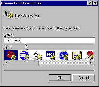
-
Select an appropriate name and icon.
-
Click OK.
The Phone Number dialog box is displayed (see Figure 2). HyperTerminal assumes that you want to make a call, so it prompts for the phone number. From the drop-down list, select the desired COM port.
Figure 2 – The Phone Number Dialog Box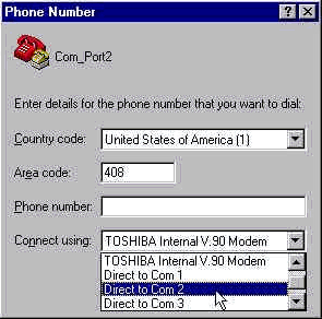
When you make a selection, the relevant Port Properties dialog box is displayed.
-
Set the COM port to 115200 bits per second, because that is the fastest speed modems can communicate over the data terminal equipment (DTE) link (see Figure 3).
Figure 3 – Set the COM Port to 115200 Bits Per Second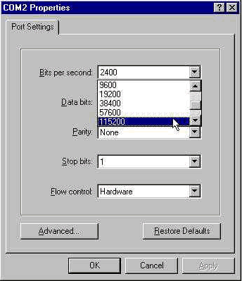
Note: This speed is not the connection speed the modems use to talk to each other. This is the speed that goes across the async modem cable between the PC and its modem.
-
Click OK.
A terminal window is displayed.
Here is an example session that uses the ATI commands numbered 3 through 11. This example includes what was entered and the responses from a modem in one of Cisco's labs:
at
OK

ati3
U.S. Robotics 56K FAX V4.6.6

OK
ati4
US Robotics 56K FAX Settings...

B0 E1 F1 M1 Q0 V1 X1 Y0
BAUD=38400 PARITY=N WORDLEN=8
DIAL=TONE ON HOOK CID=0

&A1 &B1 &C1 &D2 &G0 &H0 &I0 &K1
&M4 &N0 &P0 &R1 &S0 &T5 &U0 &Y1
S00=001 S01=000 S02=043 S03=013 S04=010 S05=008 S06=002
S07=060 S08=002 S09=006 S10=014 S11=070 S12=050 S13=000
S15=000 S16=000 S18=000 S19=000 S21=010 S22=017 S23=019
S25=005 S27=000 S28=008 S29=020 S30=000 S31=128 S32=002
S33=000 S34=000 S35=000 S36=014 S38=000 S39=000 S41=000
S42=000

LAST DIALED #: T95558653

OK
ati5
US Robotics 56K FAX NVRAM Settings...

Template Y0

DIAL=TONE B0 F1 M1 X1
BAUD=38400 PARITY=N WORDLEN=8

&A1 &B1 &G0 &H0 &I0 &K1 &M4 &N0
&P0 &R1 &S0 &T5 &U0 &Y1
S00=001 S02=043 S03=013 S04=010 S05=008 S06=002 S07=060
S08=002 S09=006 S10=014 S11=070 S12=050 S13=000 S15=000
S19=000 S21=010 S22=017 S23=019 S25=005 S27=000 S28=008
S29=020 S30=000 S31=128 S32=002 S33=000 S34=000 S35=000
S36=014 S38=000 S39=000 S41=000 S42=000


Strike a key when ready . . .


Template Y1

DIAL=TONE B0 F1 M1 X4
BAUD=115200 PARITY=N WORDLEN=8

&A3 &B1 &G0 &H2 &I2 &K1 &M4 &N0
&P0 &R1 &S0 &T5 &U0 &Y1
S00=001 S02=043 S03=013 S04=010 S05=008 S06=002 S07=060
S08=002 S09=006 S10=014 S11=070 S12=050 S13=000 S15=000
S19=000 S21=010 S22=017 S23=019 S25=005 S27=000 S28=008
S29=020 S30=000 S31=128 S32=002 S33=000 S34=000 S35=00
S36=014 S38=000 S39=000 S41=000 S42=000


STORED PHONE #0:
#1:
#2:
#3:

OK
ati6
US Robotics 56K FAX Link Diagnostics...

Chars sent 0 Chars Received 80
Chars lost 0
Octets sent 0 Octets Received 82
Blocks sent 0 Blocks Received 2
Blocks resent 0

Retrains Requested 0 Retrains Granted 0
Line Reversals 0 Blers 0
Link Timeouts 0 Link Naks 0

Data Compression V42BIS 2048/32
Equalization Long
Fallback Enabled
Protocol LAPM
Speed 24000/26400
Last Call 00:00:06

Disconnect Reason is DTR dropped

OK
ati7
Configuration Profile...

Product type US/Canada External
Product ID: 00178600
Options V32bis,V.34+,x2,V.90
Fax Options Class 1/Class 2.0
Line Options Caller ID, Distinctive Ring
Clock Freq 92.0Mhz
Eprom 256k
Ram 32k

EPROM date 5/26/98
DSP date 5/26/98

EPROM rev 4.6.6
DSP rev 4.6.6

OK

ati8
OK
ati9
(1.0USR2040\\Modem\PNPC107\US Robotics 56K FAX EXT)FF

OK
ati10
ERROR
ati11
US Robotics 56K FAX Link Diagnostics ...

Modulation V.34
Carrier Freq (Hz) 1959/1959
Symbol Rate 3429/3429
Trellis Code 64S-4D/64S-4D
Nonlinear Encoding ON/ON
Precoding ON/ON
Shaping ON/ON
Preemphasis (-dB) 8/6
Recv/Xmit Level (-dBm) 32/10
Near Echo Loss (dB) 32
Far Echo Loss (dB) 49
Carrier Offset (Hz) 294
Round Trip Delay (msec) 7
Timing Offset (ppm) -1440
SNR (dB) 32
Speed Shifts Up/Down 0/0
Status :

OK
Here is the output from a connection to one of Cisco's test systems. First, enable the speaker and DCE rate information reporting:
atw2m1
ERROR
As it turns out, w2 is not necessary on US Robotics modems.
atm1
OK
Next, dial into a static lab:
at
OK
atdt914085703932
NO CARRIER
The normal connection seems to fail. In this case, it is a noisy line, so set the modem to factory defaults (&f), turn on the speaker (m1), and cap the modem at 28.8 (&n14) with the at&fm1&n14 command:
Try to dial again. If the connection is successful you will see:
atdt914085703932
CONNECT 28800/ARQ

Welcome! Please login with username cisco, password
cisco, and type the appropriate commands for your test:

  ppp - to start ppp
  slip - to start slip
  arap - to start arap

access-3 line 29 MICA V.90 modems

User Access Verification

Username: cisco
Password:

access-3>
Log Dialin Events and Use Custom Parameters
You have determined that the connection seems to work with the new settings. Now you must update the configuration of the modem for dialup networking to reflect the changes.
To help troubleshoot modem problems, configure Windows to create a modemlog (\windows\modemlog.txt). The configuration setting only works with Telephone Application Programmable Interface (TAPI)-enabled programs, such as, DUN and HyperTerminal.
Complete these steps to set up modem logging or customer parameters on a Windows 95/98 system:
-
From the Start menu, point to Control Panel, and select Modems.
The Modems Properties dialog box is displayed.
-
Select your modem, and click the Properties button (see Figure 4).
Figure 4 – Select Your Modem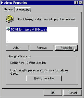
The Modem type Properties dialog box is displayed.
-
Select the Connection tab, and click the Advanced button (see Figure 5).
Figure 5 – Specify Advanced Connention Settings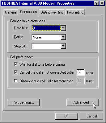
The Advanced Connention Settings dialog box is displayed.
-
Check the Record a log file check box to enable the modem logging feature (see Figure 6).
If any additional settings are needed for the modem connection to succeed, enter those commands in the Extra settings text box. Based on the previous example from the Example HyperTerminal Session section, the &n14 command has been added.
Figure 6 – Specify Extra Settings and Enable Modem Logging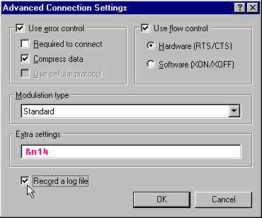
-
Click OK.
The procedure for modem logging and custom settings for Windows NT 4.0 comprises similar steps. The file will be called modemlog_modemname.txt. The file appears in the system root directory (which is usually the winnt directory, unless set otherwise). Modify the Registry Editor to enable modem logging and settings on Windows NT 3.x.
Log PPP Events
When you attempt to diagnose premature disconnect problems on a PC, it is helpful to know the type of information that was sent over the link at the PPP level. Windows 95/98 is able to create a PPP log file whenever the PPP adapter is used (/windows/ppplog.txt).
-
From the Start menu, point to Control Panel, and select Network.
The Network dialog box is displayed.
-
From the list of network components, select Dial-Up Adapter, and click the Properties button (see Figure 7).
Figure 7 – The Network Dialg Box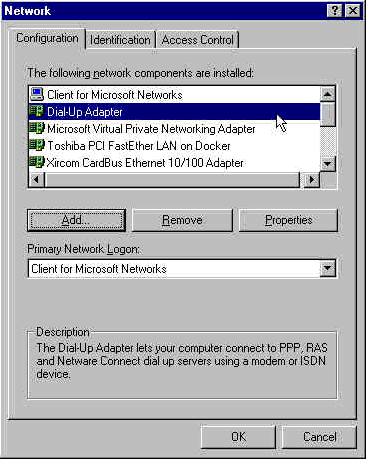
The Dial-Up Adapter Properties dialog box is displayed.
-
Select the Advanced tab. From the Properties list, select Record a log file. From the Value drop-down list, select Yes (see Figure 8).
Figure 8 – Enable PPP Logging for the Dial-Up Adapter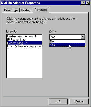
-
Click OK to complete the operation.
-
Reboot the system.
For Windows NT, edit the registry to turn on PPP logging.
Related Information
Contact Cisco
- Open a Support Case

- (Requires a Cisco Service Contract)


 Feedback