Configuring and Troubleshooting Serial Tunneling (STUN)
Available Languages
Contents
Introduction
Serial Tunneling (STUN) is the tunneling of SDLC frames across a WAN. In the traditional systems network architecture (SNA) world, remote controllers are attached to the front-end processor (FEP) through a set of modems attached over POTS (Plain Old Telephone Service) or leased lines.
Before You Begin
Conventions
For more information on document conventions, see the Cisco Technical Tips Conventions.
Prerequisites
STUN SDLC is most commonly used in two environments: FEP to remote controller, and AS/400 to remote controller.
Components Used
STUN troubleshooting using Cisco IOS® Software commands as well as AS/400 to remote controller specific issues.
Background Information
As networks move towards integration and remote offices require different type of services (such as NetBIOS, IP, IPX), it made sense from a maintenance and cost point of view to integrate all of these into a single device. For example, in the following diagram we see integration of 3270 terminals to the host with NetBIOS traffic of Windows stations.
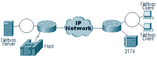
STUN permits you to use IP as a transport for Synchronous Data Link Control (SDLC) frames across a WAN or other media network. This eliminates the need to have an additional leased line or POTS. One SDLC feature of Cisco routers is media translation. In media translation, the router translates the session from SDLC to Logical Link Control, type 2 (LLC2). This is discussed in detail in Understanding and Troubleshooting SDLC to LLC Network Media Translation.
There are two types of STUN configurations: STUN Basic and STUN SDLC. The former is used for any High-Level Data Link Control (HDLC) derivative type frames and the latter is used for SDLC only frames. STUN Basic can also be used for SDLC, but features such as local-ack cannot be used. It's common to use STUN Basic for SDLC for troubleshooting purposes since SDLC-specific parameters do not need to be configured on the router.
STUN Configuration
The first command for any STUN configuration (Basic or SDLC) is stun peer-name. Without stun peer-name, the router won't let you continue with the configuration steps.
| Task | Command |
|---|---|
| Enable STUN for a particular IP address. |
stun peer-name ip-address
|
You must select a valid IP address from the router. This IP address should be the most reliable interface in the box. For the best results, configure the router with a loopback interface. (To learn about configuring loopback interfaces.
The next step is to determine the STUN mode you want to use. One mode is STUN Basic, in which it looks for starting and delimiter of the frame [7e], and transports the frame to the other side. In this mode of operation, STUN doesn't care about the specific state of the session or detailed SDLC information, like the polling address. The other mode is STUN SDLC. This mode requires more detailed decisions in the router, especially if you're running local acknowledgement or any type of multipoint. The commands used to specify a STUN mode are described in the table below:
| Task | Command |
|---|---|
| Specify a basic protocol group and assign a group number. |
stun protocol-group group-number basic
|
| Specify an SDLC protocol group and assign a group number. |
stun protocol-group group-number sdlc
|
The next step is to configure the serial interface for STUN. The group that you select in the interface must match the one defined in the protocol-group. With virtual multipoints, you should also create a stun protocol-group with different numbers for each of the virtual multipoints. Always make sure that you have configured only one secondary interface per stun-group, unless you are configuring sdlc-tg. See stun protocol-group.
| Task | Command |
|---|---|
| Enable STUN function on a serial interface.. | encapsulation stun |
| Place the interface in a previously defined STUN group. |
stun group group-number
|
Note: Don't configure this on a Cisco 7000, Cisco 7500, or any other router that has a CxBUS, CyBUS during production network time. This configuration causes the router to change the MTU of the interface to 2032 bytes, which results in a CBUS buffer carve and makes all interfaces of the router bounce (reset). In a Token Ring environment, it can mean that the Token Rings will go down for up to 16 seconds. In addition, since the Cisco 7000 is often the center of the core where this type of problem affects many users.
The next step in configuring STUN is to add the stun route statement. You can define this as stun route all or stun route [address]. The configuration options are explained below.
| Task | Command |
|---|---|
| Forward all TCP traffic for this IP address. |
stun route all tcp ip-address
|
| Specify TCP encapsulation. | stun route address address-number tcp ip-address [priority] [tcp-queue-max] |
The above commands are for TCP encapsulation peers. You can also configure STUN for direct encapsulation, but this configuration is rarely used. The most common of all the configurations is the STUN local acknowledgment setup.
These command parameters are described below:
-
The priority option in the stun route statement is used to create multiple TCP pipes between two STUN peers so that priority structures can be created using custom queueing or priority queueing.
-
The tcp_queue_max option increases or decreases the TCP queues between the two STUN peers. This is useful if the TCP session between the peers in not very reliable and you need to determine what is wrong between the peers. This option isn't commonly used in STUN environments, except when doing STUN FEP-to-FEP where much more traffic is involved.
The commands used to configure STUN with local acknowledgment are described below.
| Task | Command |
|---|---|
| Assign the STUN-enabled router an SDLC primary role. | stun sdlc-role primary |
| Assign the STUN-enabled router an SDLC secondary role. | stun sdlc-role secondary |

These commands define the "role" of the STUN setup. In the case of the host in the above diagram, the router is set to primary, which means that the host is the one that initiates the session. This makes the 3174 secondary. When using STUN Basic, you don't have to define the role, because you don't need to know who is going to initiate the session. But local acknowledgment requires details of the line itself and defining the role lets the router know the flow of the session startup, which the router needs to verify before moving to local acknowledgement.
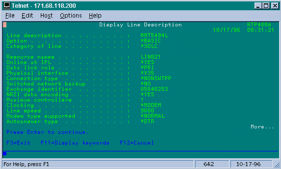
Note: In AS/400 STUN environments doing local acknowledgment, it's very important to set the role (on the line description) to *pri from *neg. The reason for this is that in a pure environment (direct modem connection), the AS/400 can negotiate the role. By coding the role that we are going to be in the line, you can ensure that the router's role is opposite from the AS/400. You usually want the AS/400 to initiate the session (with "vary on" of the line ). Go to the line configuration and set this up for *pri. The AS/400 display line description is shown below. This can only be done during create/copy of the line description.
The command to configure STUN with local acknowledgment is explained below.
| Task | Command |
|---|---|
| Establish SDLC local acknowledgment using TCP encapsulation. | stun route address address-number tcp ip-address [local-ack] [priority] [tcp-queue-max] |
The important parameter here is the stun route [address] with local-ack. Remember that STUN local-ack can be done with TCP encapsulation and Frame Relay encapsulation (using RFC 1490).
As in RSRB and DLSw, keepalives in STUN flow between the TCP peers to ensure that the peer connection is up. You can tune the keepalives if your peers are going down/up because of keepalive loss. The STUN commands used to configure keepalives are described below:
| Task | Command |
|---|---|
| Enable detection of a remote lost peer. |
stun remote-peer-keepalive seconds
|
| Number of times to attempt a peer connetion before declaring the peer "down." | stun keepalive-count quantity |
STUN Basic Sample Configuration
STUN Basic is the simplest configuration of STUN. In this mode, all packets that the router receives from one side are transported to the next. A STUN Basic configuration is shown in the diagram below:

The routers in the diagram above are configured as follows:
| 4700 | 2522 |
|---|---|
Current configuration: ! version 10.3 service udp-small-servers service tcp-small-servers ! hostname s5e ! stun peer-name 10.17.5.1 stun protocol-group 1 basic ! interface Loopback1 no ip address ! interface Serial0 ip address 10.17.5.1 255.255.255.0 clockrate 2000000 ! interface Serial1 no ip address encapsulation stun nrzi-encoding clockrate 56000 stun group 1 stun route all tcp 10.17.5.2 ! |
Current configuration: ! version 11.0 no service pad service udp-small-servers service tcp-small-servers ! hostname rick ! stun peer-name 10.17.5.2 stun protocol-group 1 basic ! interface Serial0 ip address 10.17.5.2 255.255.255.0 no fair-queue no cdp enable ! interface Serial1 ip address 10.17.92.4 255.255.255.0 no fair-queue no cdp enable ! interface Serial2 no ip address encapsulation stun nrzi-encoding clockrate 56000 stun group 1 stun route all tcp 10.17.5.1 |
STUN SDLC Sample Configuration

| 4700 | 2522 |
|---|---|
Current configuration: ! version 10.3 service udp-small-servers service tcp-small-servers ! hostname s5e ! stun peer-name 10.17.5.1 stun protocol-group 1 sdlc ! interface Loopback1 no ip address ! interface Serial0 ip address 10.17.5.1 255.255.255.0 clockrate 2000000 ! interface Serial1 no ip address encapsulation stun nrzi-encoding clockrate 56000 stun group 1 stun sdlc-role secondary sdlc address DD stun route address DD tcp 10.17.5.2 ! |
Current configuration: ! version 11.0 no service pad service udp-small-servers service tcp-small-servers ! hostname rick ! stun peer-name 10.17.5.2 stun protocol-group 1 sdlc ! interface Serial0 ip address 10.17.5.2 255.255.255.0 no fair-queue no cdp enable ! interface Serial1 ip address 10.17.92.4 255.255.255.0 no fair-queue no cdp enable ! interface Serial2 no ip address encapsulation stun nrzi-encoding clockrate 56000 stun group 1 stun sdlc-role primary sdlc address DD stun route address DD tcp 10.17.5.1 |
STUN Multipoint (with local-ack) Sample Configuration

| 4700 | 2522 |
|---|---|
hostname s5e ! ! ! stun peer-name 10.17.5.1 stun protocol-group 1 sdlc stun remote-peer-keepalive 5 ! interface Serial0 ip address 10.17.5.1 255.255.255.0 clockrate 2000000 ! interface Serial1 no ip address encapsulation stun idle-character marks nrzi-encoding clockrate 56000 stun group 1 stun sdlc-role secondary sdlc K 1 sdlc address 01 sdlc address DD stun route address 1 tcp 10.17.5.2 local-ack stun route address DD tcp 10.17.5.2 local-ack ! |
hostname rick ! ! ! stun peer-name 10.17.5.2 stun protocol-group 1 sdlc stun remote-peer-keepalive 5 ! interface Serial0 ip address 10.17.5.2 255.255.255.0 no fair-queue no cdp enable ! interface Serial2 no ip address encapsulation stun nrzi-encoding clockrate 56000 stun group 1 stun sdlc-role primary sdlc address DD stun route address DD tcp 10.17.5.1 local-ack ! interface Serial3 no ip address encapsulation stun clockrate 19200 stun group 1 stun sdlc-role primary sdlc address 01 stun route address 1 tcp 10.17.5.1 local-ack |
Note: On the AS400 router, we used sdlc k1 and idle-character marks. Refer to the Field Alert section for more details.
Show Commands
The first show command used with STUN is show stun. The output of this command depends on whether you're using STUN Basic or STUN SDLC with local-ack. In the STUN Basic portion shown below, you only see packets transmitted and received.
rick#sh stun
This peer: 10.17.5.2

 *Serial2  (group 1 [basic])
                              state       rx_pkts   tx_pkts     drops
all     TCP 10.17.5.1        closed           5729      5718         0
In the STUN SDLC with local-ack portion shown below, you get more information because now the state of the session is known.
rick#sh stun
This peer: 10.17.5.2

 *Serial2  (group 1 [sdlc])
                              state       rx_pkts   tx_pkts     drops    poll
DD     TCP 10.17.5.1        open       *      182        94         0


  Serial3  (group 1 [sdlc])
                              state       rx_pkts   tx_pkts     drops    poll
1     TCP 10.17.5.1        open       *      209        89         0

SDLC Local Acknowledgement:

 *Serial2  (group 1 [sdlc])
                                 slack_state conn disc iframe_s iframe_r
DD     TCP 10.17.5.1                  Active    1    0        0        0

  Serial3  (group 1 [sdlc])
                                 slack_state conn disc iframe_s iframe_r
1     TCP 10.17.5.1                  Active    1    0        3        3
The show interface command also provides differenct information depending on if you're running STUN Basic or STUN SDLC. The show interface for STUN Basic is the same as for a regular serial line.
Serial2 is up, line protocol is up
  Hardware is CD2430 in sync mode
  MTU 1500 bytes, BW 115 Kbit, DLY 20000 usec, rely 255/255, load 1/255
  Encapsulation STUN, loopback not set
  Last input 1:10:40, output 0:18:12, output hang never
  Last clearing of "show interface" counters 0:21:49
  Output queue 0/40, 0 drops; input queue 0/75, 0 drops
  5 minute input rate 0 bits/sec, 0 packets/sec
  5 minute output rate 0 bits/sec, 0 packets/sec
     0 packets input, 0 bytes, 0 no buffer
     Received 0 broadcasts, 0 runts, 0 giants
     0 input errors, 0 CRC, 0 frame, 0 overrun, 0 ignored, 0 abort
     4 packets output, 312 bytes, 0 underruns
     0 output errors, 0 collisions, 0 interface resets, 0 restarts
     0 output buffer failures, 0 output buffers swapped out
     0 carrier transitions
     DCD=up  DSR=up  DTR=up  RTS=up  CTS=up
The show interface for STUN SDLC with local acknowledgement provides more information. Sample output for a serial interface with local-ack is shown below.
Serial3 is up, line protocol is up
  Hardware is CD2430 in sync mode
  MTU 1500 bytes, BW 115 Kbit, DLY 20000 usec, rely 255/255, load 1/255
  Encapsulation STUN, loopback not set
    Router link station role: PRIMARY (DCE)
    Router link station metrics:
      slow-poll 10 seconds
      T1 (reply time out) 3000 milliseconds
      N1 (max frame size) 12016 bits
      N2 (retry count) 20
      poll-pause-timer 10 milliseconds
      poll-limit-value 1
      k (windowsize) 7
      modulo 8
  sdlc addr 01 state is CONNECT
      VS 1, VR 0, Remote VR 1, Current retransmit count 0
      Hold queue: 0/200 IFRAMEs 16/12
      TESTs 0/0 XIDs 0/0, DMs 0/0 FRMRs 0/0
      RNRs 316/0 SNRMs 2/0 DISC/RDs 1/0 REJs 0/0
      Poll: clear, Poll count: 0, ready for poll, chain: 01/01
  Last input 0:00:00, output 0:00:00, output hang never
  Last clearing of "show interface" counters 1d06
  Output queue 0/40, 0 drops; input queue 0/75, 0 drops
  5 minute input rate 0 bits/sec, 1 packets/sec
  5 minute output rate 0 bits/sec, 1 packets/sec
     332226 packets input, 664647 bytes, 0 no buffer
     Received 0 broadcasts, 0 runts, 0 giants
     0 input errors, 0 CRC, 0 frame, 0 overrun, 0 ignored, 0 abort
     332227 packets output, 665220 bytes, 0 underruns
     0 output errors, 0 collisions, 3444 interface resets, 0 restarts
     0 output buffer failures, 0 output buffers swapped out
     5 carrier transitions
     DCD=up  DSR=up  DTR=up  RTS=up  CTS=up
Portions of this output are explained below:
-
MTU is the physical size of the buffer that the interface uses.
-
PRIMARY (DCE) means that this is the polling station on the wire and that we are providing the clock. If we would looking at the side that is attached to the real primary, this output would have been SECONDARY.
-
N1 is the value of usable size of the SDLC frame that can be accommodated by the router's serial interface.
-
T1 is the amount of time that we expect an answer to a poll before the line is timed-out.
-
poll-pause-timer is the delta time in msec between polls.
-
k is the window size or the number of frames that we can have outstanding in between poll finals.
-
state is the current status of the session, which can be one of the states below:
-
DISCONNECT
-
CONNECTED
-
THEMBUSY (normally set as a result of this router receiving an RNR.)
-
USBUSY (normally a result of not getting a response back on the network side.)
-
-
RNRs is the number of RNRs sent/received.
-
DTR/RTS are the lines used in most half-duplex multidrop environments. When you are debugging any STUN environment and looking at the controller location, pay close attention to RTS. If this goes down intermittently while DTR and CTS are high, it's most likely the result of the DTE being half-duplex.
The final important show command for STUN is the show tcp command, which provides information regarding the TCP session between the peers. Sample output is shown below:
Stand-alone TCP connection from host 10.17.5.1
Connection state is ESTAB, I/O status: 1, unread input bytes: 0
Local host: 10.17.5.2, Local port: 1994
Foreign host: 10.17.5.1, Foreign port: 11035

Enqueued packets for retransmit: 0, input: 0, saved: 0

Event Timers (current time is 0x1B2E50):
Timer          Starts    Wakeups            Next
Retrans           229          0             0x0
TimeWait            0          0             0x0
AckHold           229          0             0x0
SendWnd             0          0             0x0
KeepAlive           0          0             0x0
GiveUp              0          0             0x0
PmtuAger            0          0             0x0

iss: 2847665974  snduna: 2847667954  sndnxt: 2847667954     sndwnd:   9728
irs: 3999497423  rcvnxt: 3999499452  rcvwnd:       9672  delrcvwnd:    568

SRTT: 300 ms, RTTO: 607 ms, RTV: 3 ms, KRTT: 0 ms
minRTT: 0 ms, maxRTT: 300 ms, ACK hold: 300 ms
Flags: passive open, higher precedence

Datagrams (max data segment is 1460 bytes):
Rcvd: 459 (out of order: 0), with data: 229, total data bytes: 2028
Sent: 457 (retransmit: 0), with data: 228, total data bytes: 1979
Troubleshooting
Troubleshooting a STUN configuration is the same as with any peer-to-peer convention. If you are experiencing problems in the transport, this needs to be diagnosed before you can start troubleshooting the SDLC/STUN portion. Usually, the first step is to ping from peer to peer to make sure that IP is set up correctly. Also, ping with extended packet types to make sure that the transport is reliable.
Troubleshooting SDLC Basic
This section covers troubleshooting a STUN Basic setup. In this example, assume that the WAN is functioning correctly.

This scenario has a STUN Basic setup to connect the 5494 to the AS/400. The first thing to verify with any STUN setup is that the peers are set up in the router. To determine this, use the show stun peer command. It provides information about the state of the peer and the packets that were transmitted/received. Sample output is shown below:
rick#sh stun peer
This peer: 10.17.5.2

 *Serial2  (group 1 [basic])
                              state       rx_pkts   tx_pkts     drops
all     TCP 10.17.5.1        open             5729      5718         0
If the peer is open, as above, use the show interfacecommand to determine what is happening to the packets. Sample output for this command is shown below:
Serial2 is up, line protocol is up
  Hardware is CD2430 in sync mode
  MTU 1500 bytes, BW 115 Kbit, DLY 20000 usec, rely 255/255, load 1/255
  Encapsulation STUN, loopback not set
  Last input 1:10:40, output 0:18:12, output hang never
  Last clearing of "show interface" counters 0:21:49
  Output queue 0/40, 0 drops; input queue 0/75, 0 drops
  5 minute input rate 0 bits/sec, 0 packets/sec
  5 minute output rate 0 bits/sec, 0 packets/sec
     0 packets input, 0 bytes, 0 no buffer
     Received 0 broadcasts, 0 runts, 0 giants
     0 input errors, 0 CRC, 0 frame, 0 overrun, 0 ignored, 0 abort
     4 packets output, 312 bytes, 0 underruns
     0 output errors, 0 collisions, 0 interface resets, 0 restarts
     0 output buffer failures, 0 output buffers swapped out
     0 carrier transitions
     DCD=up  DSR=up  DTR=up  RTS=up  CTS=up
First, verify if the router has the all serial signals up. At the bottom of the output above, we can see that the all the signals are "up" for the "Serial2" on the 2522. DTR and RTS indicate that the controller has already activated the line itself and is waiting for the AS/400 to send the initial conversation.
Next, check the show interface for the router's AS/400 side. In the output shown below, we see that the serial interface that attaches to the AS/400 is down/down. This means that the AS/400 is probably "varied off." If the line is "varied on" and you can't get the line up or are running half-duplex, then you need to check the RS-232/V.35 connection.
Serial1 is down, line protocol is down
  Hardware is HD64570
  MTU 1500 bytes, BW 1544 Kbit, DLY 20000 usec, rely 255/255, load 1/255
  Encapsulation STUN, loopback not set
  Last input never, output 1:51:24, output hang never
  Last clearing of "show interface" counters 0:00:01
  Output queue 0/40, 0 drops; input queue 0/75, 0 drops
  5 minute input rate 0 bits/sec, 0 packets/sec
  5 minute output rate 0 bits/sec, 0 packets/sec
     0 packets input, 0 bytes, 0 no buffer
     Received 0 broadcasts, 0 runts, 0 giants
     0 input errors, 0 CRC, 0 frame, 0 overrun, 0 ignored, 0 abort
     0 packets output, 0 bytes, 0 underruns
     0 output errors, 0 collisions, 0 interface resets, 0 restarts
     0 output buffer failures, 0 output buffers swapped out
     0 carrier transitions
     DCD=up  DSR=up  DTR=down  RTS=down  CTS=up
s5e#
At this point, check the "Work with Configuration Status" for that specific controller, which is an AS/400 screen that looks like:
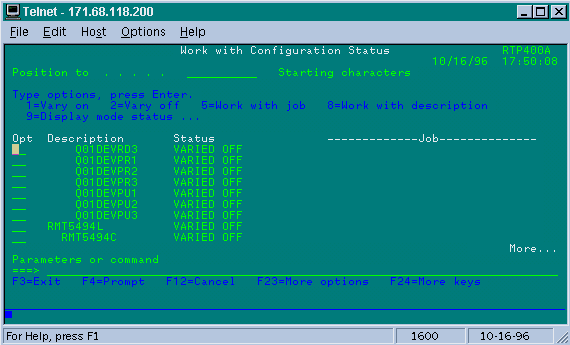
Next, vary on the line definition. You should then see that the router goes line up/up. If the line comes up/up but the controller still doesn't come up, check the interface to verify if any packets have hit the interface inbound from the AS/400. If the count is zero, check the encoding mechanism for the SDLC line on the AS/400. This is located on the display line description, as shown below.
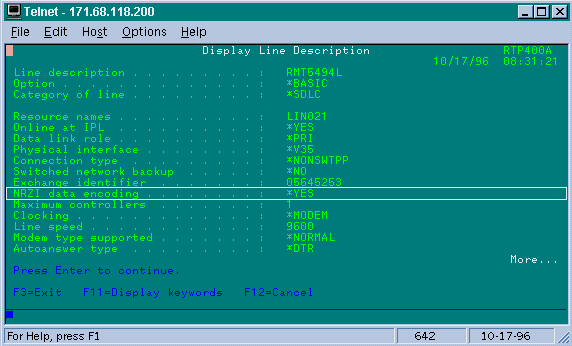
Note: On this screen, we can see that the line encoding is set for NRZI encoding. This needs to be turned on with the configuration option nrzi-encoding on the router.
This setup doesn't require NRZ/NRZI encoding end to end, as in conventional SDLC point-to-point conventions, but can be NRZI at one side and NRZ at the other. But remember that the encoding does have to be the same between devices that share the SDLC line.
NRZI requires careful consideration. In the new routers like the Cisco 2500 and 4500, NRZI is set via software. But with older platforms, including the NP-2T for the Cisco 4000, you need to change jumpers on the boards themselves. In such cases, it's probably easier to change the AS/400 to NRZ/NRZI. But, if you need to change the jumpers, refer to the Cisco hardware documenation for your specific platform.
If the problem persists, do a a debug stun packet 1. This command gives us the following information:
STUN basic: 0:00:35 Serial1         SDI:   Data: c0bf324c056452530000
%LINEPROTO-5-UPDOWN: Line protocol on Interface Serial1, changed state to down
%LINK-3-UPDOWN: Interface Serial1, changed state to down
STUN basic: 0:00:38 Serial1         SDI:   Data: c0bf324c056452530000
%LINEPROTO-5-UPDOWN: Line protocol on Interface Serial1, changed state to up
%LINK-3-UPDOWN: Interface Serial1, changed state to up
%LINEPROTO-5-UPDOWN: Line protocol on Interface Serial1, changed state to down
STUN basic: 0:00:35 Serial1         SDI:   Data: c0bf324c056452530000
%LINEPROTO-5-UPDOWN: Line protocol on Interface Serial1, changed state to up
%LINEPROTO-5-UPDOWN: Line protocol on Interface Serial1, changed state to down
%LINK-3-UPDOWN: Interface Serial1, changed state to down
You can see several XIDs flowing from the AS/400, but there was no response to them (CO is the polling address and bf is the XID). We know that the packet is coming from the AS/400 because the packet originated from SDI. There are two types of incoming packets in this command output:
-
SDI: Serial incoming, which are packets received from the SDLC interface.
-
NDI: Network incoming, which are packets de-encapsulated from the WAN.
Next, look at the XID portion of the frame itself. In this example, the AS/400 is sending an XID along with its IDBLOCK and IDNUM, 05645253.
This is a timeout issue, because the controller isn't responding. In the AS/400, look at the "sysopr message queue" to see if there are any messages indicating a problem. A "SYSOPR" screen with a failure is shown below.
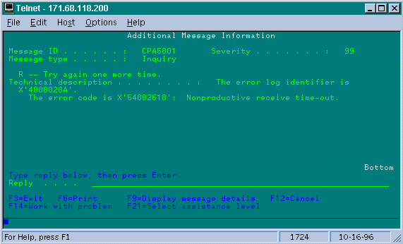
Now on the 2522, turn on debug stun packet 1 to see if the packets are getting sent to the controller. Sample command output is shown below:
STUN basic: 0:00:34 Serial2         NDI:   Data: c0bf324c056452530000
STUN basic: 0:00:42 Serial2         NDI:   Data: c0bf324c056452530000
This shows us that the XID that originated on the AS/400 side is getting through to the controller, but the controller isn't responding, which means that it is a controller problem. A show interface shows us if all the control leads are up or not:
Serial2 is up, line protocol is up
  Hardware is CD2430 in sync mode
  MTU 1500 bytes, BW 115 Kbit, DLY 20000 usec, rely 255/255, load 1/255
  Encapsulation STUN, loopback not set
  Last input 0:50:56, output 0:00:23, output hang never
  Last clearing of "show interface" counters 0:02:06
  Output queue 0/40, 0 drops; input queue 0/75, 0 drops
  5 minute input rate 0 bits/sec, 0 packets/sec
  5 minute output rate 0 bits/sec, 0 packets/sec
     0 packets input, 0 bytes, 0 no buffer
     Received 0 broadcasts, 0 runts, 0 giants
     0 input errors, 0 CRC, 0 frame, 0 overrun, 0 ignored, 0 abort
     1 packets output, 78 bytes, 0 underruns
     0 output errors, 0 collisions, 0 interface resets, 0 restarts
     0 output buffer failures, 0 output buffers swapped out
     0 carrier transitions
     DCD=up  DSR=up  DTR=up  RTS=up  CTS=up
The control leads are up and interface shows up/up. We can also see that the router is outputting packets, but no packets are incoming. This points to the incorrect polling address configured on the AS/400, so the next step is to verify the controller's polling address.
Each type of controller has a unique way of configuring the polling address, so you need to verify this with the controller manuals for your controller.
In this example, we found out that the controller was using the polling address of "DD." After changing this on the AS/400, the output of debug stun packet becomes:
STUN basic: 0:24:03 Serial2         NDI:   Data: ddbf324c056452530000
STUN basic: 0:00:00 Serial2         SDI:   Data: ddbf3244073000dd0000
STUN basic: 0:00:00 Serial2         NDI:   Data: dd93
STUN basic: 0:00:00 Serial2         SDI:   Data: dd73
STUN basic: 0:00:00 Serial2         NDI:   Data: dd11
STUN basic: 0:00:00 Serial2         SDI:   Data: dd11
STUN basic: 0:00:00 Serial2         NDI:   Data: dd11
STUN basic: 0:00:00 Serial2         SDI:   Data: dd102f00000200016b80
STUN basic: 0:00:00 Serial2         NDI:   Data: dd31
STUN basic: 0:00:00 Serial2         SDI:   Data: dd11
STUN basic: 0:00:00 Serial2         NDI:   Data: dd31
STUN basic: 0:00:00 Serial2         SDI:   Data: dd11
.
.
.
.
STUN basic: 0:00:00 Serial2         NDI:   Data: dd31
STUN basic: 0:00:00 Serial2         SDI:   Data: dd71
STUN basic: 0:00:00 Serial2         NDI:   Data: dd362f00020080004b80
STUN basic: 0:00:00 Serial2         NDI:   Data: dd31
STUN basic: 0:00:00 Serial2         NDI:   Data: dd53
STUN basic: 0:00:00 Serial2         SDI:   Data: dd73
This debug output helps to determine the following information:
STUN basic: 0:24:03 Serial2 NDI: Data: ddbf324c056452530000
This line contains the XID from the AS/400 to the controller. This comes from NDI (coming from the cloud), dd (polling address), bf (the XID), and the IDBLOCK and IDNUM (05645253).
STUN basic: 0:00:00 Serial2 SDI: Data: ddbf3244073000dd0000
This is the response from the controller. This is indicated by SDI (coming from SDLC line) and the same as above, with the exception of the XID response (073000dd), because this is a 5494.
STUN basic: 0:00:00 Serial2 NDI: Data: dd93
This is the SNRM (93)from the AS/400 to the controller, which is the primary in this configuration.
STUN basic: 0:00:00 Serial2 SDI: Data: dd73
Here we see the controller responding (SDI) with a UA (73), which means that the session is up and running. Next, we should see the disconnect coming from the AS/400 as the line was varied off.
STUN basic: 0:00:00 Serial2         NDI:   Data: dd53
STUN basic: 0:00:00 Serial2         SDI:   Data: dd73
These lines show the DISC (53) and the UA response. The line is now down. Following is a table with values needed to debug these issues.
| Control Field - Unnumbered (1 byte) | ||
|---|---|---|
000z 0011 0001 0111 0001 0111 0001 1111 0011 0011 0101 0011 0101 0011 0101 0011 0111 0011 1001 0011 1001 0111 101z 1111 110z 0111 111z 0011 |
03-13 UI 07-17 SIM 07-17 RIM 0F-1F DM 23-33 UP 43-53 DISC 43-53 RD 43-53 RD 63-73 UA 83-93 SNRM 87-97 FRMR AF-BF XID C7-D7 CFGR E3-F3 TEST |
Unnumbered Information Set Initialization mode Request Intialization Mode Secondary in Disconnect Mode Unumber Poll Disconnect Request Disconnect Secondary Requests Disconnect Unnumbered Acknowledgement Set Normal Response Mode Frame Reject Exchange Identification Configure I-Field contains test pattern |
| Control Field - Supervisory (2 bytes) | ||
|---|---|---|
rrrz cc01 rrrz 0001 rrrz 0101 rrrz 1001 |
xx-xx x1-x1 x5-x5 x9-x9 |
Supervisory Format Receiver Ready Receiver Not Ready Reject |
| Control Field - Information frames (2 bytes) | ||
|---|---|---|
rrr1 sssz |
xx-xx |
Information format |
Key:
z = The poll final bit may be either 0 or 1
rrr = Number of block expected to be received
sss = Number of block being sent
Troubleshooting STUN SDLC With and Without Local Acknowledgment
This section covers the same scenario with local acknowledgement configured.

In contrast to STUN Basic, STUN SDLC requires that you specify the correct polling address or the router will not even see the packets come in. This is why sometimes STUN Basic is used to find the polling address when you don't have the information, or can't get to the host or the AS/400. The diagram above shows a multipoint scenario with local-ack.
In a traditional point-to-point environment, the polling goes end to end. When local acknowledgment is introduced, the polling is terminated at each end of the cloud, so each router has to mantain a finite state machine. This machine keeps track of all sessions and needs to know the state of the line for each polled station. Because of this, you have to make sure that the stations are following the SDLC protocol.
First, verify that you are in the correct STUN role. AS/400s have trouble negotiating the role with the controller in traditional point-to-point environments. The line description is shown below.
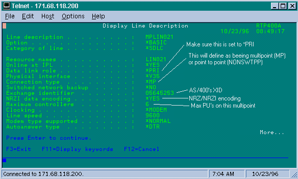
This shows us that the router interface needs to configured for a secondary role. Always check the line and verify that it is *PRI , because the AS/400 defaults to *NEG when you create it. NRZI is set to *YES, so you need to code nrzi-encoding. Also, code idle-character marks and set the window to one (1) using sdlc k 1. (Refer to the FNA-IOS-0696-02 Field Alert for an in-depth description of why idle-character marks is required on the interface.) This coding is shown below:
interface Serial1
no ip address
encapsulation stun
idle-character marks
nrzi-encoding
clockrate 56000 (real clockrate on the line; see note about as400 line speed)
stun group 1
stun sdlc-role secondary (this must be secondary because the line is primary)
sdlc K 1
sdlc address 01
sdlc address DD
stun route address 1 tcp 10.17.5.2 local-ack
stun route address DD tcp 10.17.5.2 local-ack
Note: The clocking that the router provides is independent of the Line speed parameter that is configured on the AS/400 line. (This parameter is used for performance calulations; it can be left at the default of 9600.) The Exchange identifier that is configured on the line is that of the AS/400, such as the XID that the AS/400 will send. The Maximum controllers is the number of number of PUs (controllers) that can be created and attached to this line.
The first of the two controllers attached to this line, an IBM 5494, is shown in the screen below.
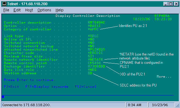
We can see that the first controller is going to be a PU 2.1 because the category of the controller is "*APPC." This is the abbreviation for Advance Program-to-Program Communications, which can only be accomplished via a T2.1 connection. The remote network identifier is again related to APPN/APPC and referred to as the "NETID." "*NETATR" is a parameter that specifies using the NETID defined in the data area called "Network Attributes." You can display this data area using the command DSPNETA, and substitute the values accordingly. The "Remote Control point" or "CP_name" is the control point name that you configured in the PU2.1. In this case, it is CP5494. The Data link role can be left as *NEG. The "Station address" needs to match the "sdlc address DD" that was configured on both the secondary interface as well as one of the primary interfaces.
interface Serial2
 no ip address
 encapsulation stun
 nrzi-encoding
 clockrate 56000
 stun group 1
 stun sdlc-role primary
 sdlc address DD
 stun route address DD tcp 10.17.5.1 local-ack
You can see that most of the information that resides in the controller description is pertinent to the physcial unit itself, and not configurable in the router.
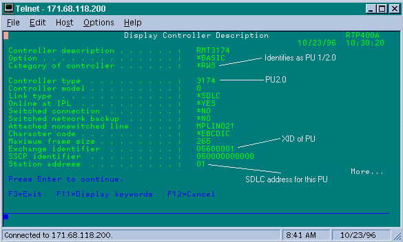
On this screen, the second controller (PU) is actually a 3174, which is a PU type 2. The XID configured in this 3174 is 05600001. The "Station address", or sdlc address, being used is 01. You need an "sdlc address 01" configured on the secondary interface and one of the remote primary interfaces. As you can see below, the configuration for a PU2 is less involved than a PU2.1.
interface Serial3
 no ip address
 encapsulation stun
 clockrate 19200
 stun group 1
 stun sdlc-role primary
 sdlc address 01
 stun route address 1 tcp 10.17.5.1 local-ack
The Display Networks Attributes (DSPNETA) in the AS/400 is shown below:
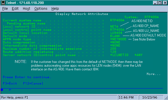
This screen shows that the AS/400 is currently configured for Network ID "NETA," which means that the 5494 needs to be configured for the same network. This, as well as the rest of the APPN-specific configuration, can be found on the second configuration screen in the 5494. The local Control Point name of the AS/400 is "RTP400A." The LU Name of the AS/400 is "LU9404;" this needs to match up with what is configured in the 5494's Partner LU definition field. The mode description that is being used by the 5494 needs to match what is in the device description. For example, if the device says "*NETATR," then it needs to match the default of "BLANK".
The APPC Device description created for the 5494 is shown below.
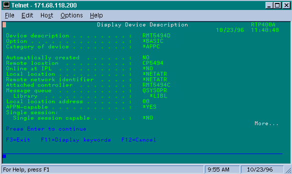
This screen shows that the device description for the 5494 has a Remote CP name of "CP5494;" this needs to match what is configured on the 5494. The NETID and Local Location have defaulted to "*NETATR," which were coded to LU9404 and NETA in the previous example. Again, these need to match the Partner LU name and NETID fields in the 5494.
The final piece of the device configuration that is pertinent to getting a connection established is shown below.
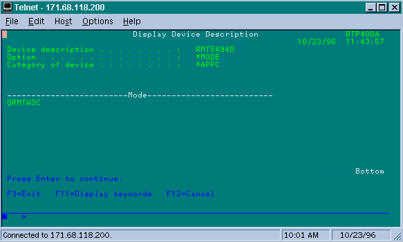
This screen shows that the mode being used on the device description is "QRMTWSC." This is not the default found in the *NETATR, so that means it has been overridden in the device description. This is one of the default modes supplied by IBM as part of the base APPN support on the AS/400. If you see anything different, contact IBM, because they are running with a mode description that they created. This example establishes a basic connection; if you want to display the information about the modes available you can use the command WRKMODD or Work Mode Descriptions.
The Mode Description is shown below.
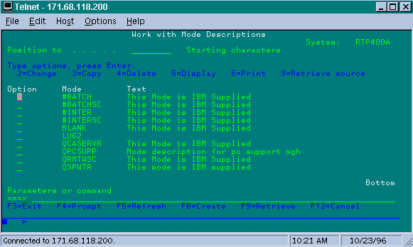
This screen clearly identifies the Mode definitions supplied by IBM.
Troubleshooting SDLC Full Duplex Multipoint interface
When doing local acknowledgment in a multipoint environment with AS/400s, be aware of how the "SDLC Full Duplex Multipoint interface" has been implemented on the AS/400, SYS/38, and SYS/36 mini-mainframes. The FNA-IOS-0696-02 Field Alert (included below) explains the type of problems that can occur in this situation.
Brief Description
The router cable modification connecting "carrier detect" to ground will not prevent periodic SDLC line resets from an AS/400 if the AS/400 has had IBM PTF# MF10030 applied. This alert applies only to STUN full duplex multi-drop connections to an AS/400 where the router SDLC cable has been modified to disable carrier detect.
Impact
Users may experience periodic reset of the STUN connection and all SDLC secondary devices, resulting in an unreliable connection.
Full Description/Background
In a multi-drop environment, an AS/400 behaves differently from other IBM devices. Whereas a FEP accepts either 0x7E characters (flags) or 0xFF characters (marks) as "idle" space between frames, an AS/400 treats flags and marks differently. Only a mark is interpreted as an idle character. A flag is interpreted to mean "line is still active -more data is pending." A Cisco router can be configured to send either flags or marks but not both. It will not alternate between the two to reflect line state. The default is for router to send flags.
This difference poses a problem in full duplex multi-drop environments. Normally the AS/400 goes from device to device, polling each one for data. If a device fails to respond and the AS/400 thinks the line is still active, it will reset the entire line. Since the default is for the router to send flags, the AS/400 will always see an active line and will line reset instead of simply polling the next device.
To avoid this problem, Cisco has historically recommended a cable modification that disables the carrier detect (CD) signal. This modification takes advantage of AS/400 logic that interprets absence of carrier to mean "idle line state." Hence, with the modification, an AS/400 always detects idle line state regardless of the inter-frame characters being sent by the router. So, if a secondary device fails to respond, the AS/400 will check CD, see an idle line and move on to poll the next station.
Recently, IBM released AS/400 problem fix PTF# MF10030 that changes the carrier detect logic on multi-drop lines. With this fix installed, an AS/400 completely ignores the state of CD on full duplex multi-drop lines. As a result, the Cisco cable modification is no longer effective at preventing periodic line resets.
Workaround
Two workarounds are available, depending on the router model and the version of Cisco IOS running. Both options require configuration changes to the router connected to the AS/400.
Option 1
Change the SDLC idle character from the default flag character to a mark character. The idle character can be changed using the router interface configuration command:
idle-character marks
Add this command to the SDLC serial interface connected to the AS/400. This command will cause the router to always transmit mark characters for a pause between frames. So, if a secondary device misses a poll, the AS/400 will see an idle line and move on to poll the next device. Unfortunately, this also means the AS/400 will see idle even if more data frames are on the way from the device. The AS/400 will only acknowledge the first frame, even if the poll/final bit is 0. It will then ignore all subsequent frames and poll the next device causing unnecessary frame retransmissions. To avoid the retransmissions, you must also set the SDLC window size to 1 with the command:
sdlc k 1
Note: The idle-character command is supported in Cisco IOS version 10.0(5.2) and later, and works on 2500s, 4x00 with NP-4T, and 70x0/75xx routers.
Option 2
Enable detection of inactive secondary devices with the interface command:
stun quick-response
This command will cause the router to respond with a "disconnect mode" (DM) frame for any inactive secondary device polled by the AS/400. The AS/400 will then proceed to poll the next device without resetting the line.
Note: This command is supported in Cisco IOS 11.1, 11.0(3.1) and later or 10.3(7.2) and later.
Tip: If you experience any problems bringing up the multipoint line with the quick-response configured, use option 1. The stun quick-response code in the router is part of the finite state machine for local-ack, which can get out of step with some PUs. We have tested the code in the lab and verified its interoperability with the 5494, 5394, and Perl494E. It is possible to run into problems if the PU you are trying to attach has timers set differently from what the quick_response is expecting.
 Feedback