- Title and copyright: Inverse Multiplexing over ATM Port Adapter Installation and Configuration
- Preface: Inverse Multiplexing over ATM Port Adapter Installation and Configuration
- Overview: Inverse Multiplexing over ATM Port Adapter Installation and Configuration
- Preparing to Install the PA-A3 IMA Port Adapter
- Removing and Installing the PA-A3 IMA Port Adapter
- Configuring the PA-A3 IMA Port Adapter
Inverse Multiplexing over ATM Port Adapter Installation and Configuration
Bias-Free Language
The documentation set for this product strives to use bias-free language. For the purposes of this documentation set, bias-free is defined as language that does not imply discrimination based on age, disability, gender, racial identity, ethnic identity, sexual orientation, socioeconomic status, and intersectionality. Exceptions may be present in the documentation due to language that is hardcoded in the user interfaces of the product software, language used based on RFP documentation, or language that is used by a referenced third-party product. Learn more about how Cisco is using Inclusive Language.
- Updated:
- September 14, 2007
Chapter: Configuring the PA-A3 IMA Port Adapter
Configuring the PA-A3-IMA
To continue your PA-A3-IMA port adapter installation, you must configure the IMA interfaces as IMA groups or as individual ATM interfaces. The instructions that follow apply to all supported platforms. Minor differences among the platforms—with Cisco IOS software commands—are noted.
This chapter contains the following sections:
•![]() Using the EXEC Command Interpreter
Using the EXEC Command Interpreter
•![]() Configuring Ports on the PA-A3-IMA
Configuring Ports on the PA-A3-IMA
•![]() Configuring ATM Virtual Circuits
Configuring ATM Virtual Circuits
•![]() Configuring Permanent Virtual Circuits
Configuring Permanent Virtual Circuits
•![]() Configuring Switched Virtual Circuits
Configuring Switched Virtual Circuits
•![]() Configuring Classical IP and ARP over ATM
Configuring Classical IP and ARP over ATM
Using the EXEC Command Interpreter
You modify the configuration of your router through the software command interpreter called the EXEC (also called enable mode). You must enter the privileged level of the EXEC command interpreter with the enable command before you can use the configure command to configure a new interface or change the existing configuration of an interface. The system prompts you for a password if one has been set.The system prompt for the privileged level ends with a pound sign (#) instead of an angle bracket (>).
At the console terminal, use the following procedure to enter the privileged level:
Step 1 ![]() At the user-level EXEC prompt, enter the enable command. The EXEC prompts you for a privileged-level password as follows:
At the user-level EXEC prompt, enter the enable command. The EXEC prompts you for a privileged-level password as follows:
Router> enable
Password:
Step 2 ![]() Enter the password (the password is case sensitive). For security purposes, the password is not displayed.
Enter the password (the password is case sensitive). For security purposes, the password is not displayed.
When you enter the correct password, the system displays the privileged-mode system prompt (#):
Router#
Configuring the Interfaces
After you verify that the new PA-A3-IMA is installed correctly (the ENABLED LED goes on), use the privileged-level configure command to configure the new interfaces. Be prepared with the information you need, such as the following:
•![]() Protocols you plan to route on each new interface
Protocols you plan to route on each new interface
•![]() IP addresses, if you plan to configure the interfaces for IP routing
IP addresses, if you plan to configure the interfaces for IP routing
•![]() Bridging protocols you plan to use
Bridging protocols you plan to use
If you installed a new PA-A3-IMA or if you want to change the configuration of an existing interface, you must enter configuration mode to configure the new interfaces. If you replaced a PA-A3-IMA that was previously configured, the system recognizes the new interfaces and brings each of them up in their existing configurations.
For a summary of the configuration options available and instructions for configuring interfaces on a PA-A3-IMA, refer to the appropriate configuration publications listed in the "Related Documentation" section on page ii.
You execute configuration commands from the privileged level of the EXEC command interpreter, which usually requires password access. Contact your system administrator, if necessary, to obtain password access. (See the "Using the EXEC Command Interpreter" section for an explanation of the privileged level of the EXEC.)
This section contains the following subsections:
•![]() Performing a Basic Configuration
Performing a Basic Configuration
Shutting Down an Interface
Before you remove an interface cable or remove a port adapter that you will not replace, use the shutdown command to shut down (disable) the interfaces to prevent anomalies when you reinstall the new or reconfigured interface processor. When you shut down an interface, it is designated administratively down in the show command displays.
Follow these steps to shut down an interface:
Step 1 ![]() Enter the privileged level of the EXEC command interpreter (also called enable mode). (See the "Using the EXEC Command Interpreter" section for instructions.)
Enter the privileged level of the EXEC command interpreter (also called enable mode). (See the "Using the EXEC Command Interpreter" section for instructions.)
Step 2 ![]() At the privileged-level prompt, enter configuration mode and specify that the console terminal is the source of the configuration subcommands, as follows:
At the privileged-level prompt, enter configuration mode and specify that the console terminal is the source of the configuration subcommands, as follows:
Router# configure terminal
Enter configuration commands, one per line. End with CNTL/Z.
Router(config)#
Step 3 ![]() Shut down interfaces by entering the interface atm subcommand (followed by the interface address of the interface), and then enter the shutdown command.
Shut down interfaces by entering the interface atm subcommand (followed by the interface address of the interface), and then enter the shutdown command.
When you have finished, press Ctrl-Z—hold down the Control key while you press Z—or enter end or exit to exit configuration mode and return to the EXEC command interpreter.
Table 4-1 shows the shutdown command syntax for the supported platforms:

Note ![]() If you need to shut down additional interfaces, enter the interface atm command (followed by the interface address of the interface) for each of the interfaces on your port adapter. Use the no shutdown command to enable the interface.
If you need to shut down additional interfaces, enter the interface atm command (followed by the interface address of the interface) for each of the interfaces on your port adapter. Use the no shutdown command to enable the interface.
Step 4 ![]() Write the new configuration to NVRAM as follows:
Write the new configuration to NVRAM as follows:
Router# copy running-config startup-config
[OK]
Router#
The system displays an OK message when the configuration has been stored in NVRAM.
Step 5 ![]() Verify that the new interfaces are now in the correct state (shut down) using the show interfaces command (followed by the interface type and interface address of the interface) to display the specific interface.
Verify that the new interfaces are now in the correct state (shut down) using the show interfaces command (followed by the interface type and interface address of the interface) to display the specific interface.
Table 4-2 provides examples of the show interfaces atm command for the supported platforms.
Step 6 ![]() Re-enable interfaces by doing the following:
Re-enable interfaces by doing the following:
a. ![]() Repeat Step 3 to re-enable an interface. Substitute the no shutdown command for the shutdown command.
Repeat Step 3 to re-enable an interface. Substitute the no shutdown command for the shutdown command.
b. ![]() Repeat Step 4 to write the new configuration to memory.
Repeat Step 4 to write the new configuration to memory.
c. ![]() Repeat Step 5 to verify that the interfaces are in the correct state. Use the show interfaces command followed by the interface type and interface address of the interface.
Repeat Step 5 to verify that the interfaces are in the correct state. Use the show interfaces command followed by the interface type and interface address of the interface.
For complete descriptions of software configuration commands, refer to the publications listed in the "Related Documentation" section on page ii.
Performing a Basic Configuration
Following are instructions for a basic configuration. You might also need to enter other configuration subcommands, depending on the requirements for your system configuration and the protocols you plan to route on the interface. For complete descriptions of configuration subcommands and the configuration options available for ATM interfaces, refer to the appropriate software documentation.
In the following procedure press the Return key after each step unless otherwise noted. At any time you can exit the privileged level and return to the user level by entering disable at the prompt, as follows:
Router# disable
Router>
Step 1 ![]() Enter configuration mode and specify that the console terminal is the source of the configuration subcommands, as follows:
Enter configuration mode and specify that the console terminal is the source of the configuration subcommands, as follows:
Router# configure terminal
Enter configuration commands, one per line. End with CNTL/Z.
Router(config)#
Step 2 ![]() Specify the first interface to configure by entering the interface atm subcommand, followed by the interface address of the interface you plan to configure.
Specify the first interface to configure by entering the interface atm subcommand, followed by the interface address of the interface you plan to configure.
Table 4-3 provides examples of the interface atm subcommand for the supported platforms.
Note ![]() When the PA-A3-IMA port adapter comes up for the first time, all ports come up in ATM UNI mode.
When the PA-A3-IMA port adapter comes up for the first time, all ports come up in ATM UNI mode.
Step 3 ![]() Assign an IP address and subnet mask to the interface (if IP routing is enabled on the system) by using the ip address subcommand, as in the following example:
Assign an IP address and subnet mask to the interface (if IP routing is enabled on the system) by using the ip address subcommand, as in the following example:
Router(config-if)# ip address 10.0.0.10 255.255.255.0
Step 4 ![]() Add any additional configuration subcommands required to enable routing protocols and set the interface characteristics.
Add any additional configuration subcommands required to enable routing protocols and set the interface characteristics.
Step 5 ![]() Configure the port for the type of framing used by entering the framing configuration command. The following example sets the framing type of a T1 port to Extended Superframe (ESF):
Configure the port for the type of framing used by entering the framing configuration command. The following example sets the framing type of a T1 port to Extended Superframe (ESF):
Router(config-if)# framing esf
The following example sets the framing type of an E1 port to CRC4:
Router(config-if)# framing crc4
The default is ESF for T1 ports and pcm30adm for E1 ports.
Step 6 ![]() Configure transmit attenuation and cable length for applicable T1 links using the lbo configuration command. The following example sets the cable length to long and the gain to 26 dB, with a -15 dB pulse:
Configure transmit attenuation and cable length for applicable T1 links using the lbo configuration command. The following example sets the cable length to long and the gain to 26 dB, with a -15 dB pulse:
Router(config-if)# lbo long gain26 -15db
Note ![]() Each T1 port can operate in long-haul or short-haul mode. In long-haul mode, the user must specify the gain and the line build-out. The default value is long-haul with gain 26 dB and 0 dB line build-out. In short-haul mode, the user must specify the cable length in feet. The range is from 0 to 655 feet. The actual mapping is shown in Table 4-4 below.
Each T1 port can operate in long-haul or short-haul mode. In long-haul mode, the user must specify the gain and the line build-out. The default value is long-haul with gain 26 dB and 0 dB line build-out. In short-haul mode, the user must specify the cable length in feet. The range is from 0 to 655 feet. The actual mapping is shown in Table 4-4 below.
Step 7 ![]() Set the clock source of the port using the clock source command. The default value is line. The example below shows the clock source being set to internal:
Set the clock source of the port using the clock source command. The default value is line. The example below shows the clock source being set to internal:
Router(config-if)# clock source internal
Step 8 ![]() Set the line code of the port using the linecode command. The example below sets the line code of a T1 port to alternate mark inversion (AMI):
Set the line code of the port using the linecode command. The example below sets the line code of a T1 port to alternate mark inversion (AMI):
Router(config-if)# linecode ami
The default values are b8zs for T1 and hdb3 for E1.
Step 9 ![]() On T1 ports with ESF framing, use the fdl command to enable Facility Data Link (FDL) performance reporting. The default value is no fdl. The example below selects ANSI T1.403 for Facility Data Link support.
On T1 ports with ESF framing, use the fdl command to enable Facility Data Link (FDL) performance reporting. The default value is no fdl. The example below selects ANSI T1.403 for Facility Data Link support.
Router(config-if)# fdl ansi
Step 10 ![]() On E1 ports, set the national and international reserve bits using the national reserve command as in the example below:
On E1 ports, set the national and international reserve bits using the national reserve command as in the example below:
Router(config-if)# national reserve 0 1 1 1 1 0
The default values are 1 1 1 1 1 1 1.
Step 11 ![]() To enable cell payload scrambling, use the scrambling command. The default value is no scrambling.
To enable cell payload scrambling, use the scrambling command. The default value is no scrambling.
Router(config-if)# scrambling cell-payload
Step 12 ![]() Set the maximum transmission unit (MTU) size. The range is 64 through 9188 bytes. The default is 4470 bytes. Use the mtu command in interface configuration mode to change the maximum MTU packet size, as shown in the following example:
Set the maximum transmission unit (MTU) size. The range is 64 through 9188 bytes. The default is 4470 bytes. Use the mtu command in interface configuration mode to change the maximum MTU packet size, as shown in the following example:
Router(config-if)# mtu 5260
Step 13 ![]() Change the shutdown state to up and enable the interface:
Change the shutdown state to up and enable the interface:
Router(config-int)# no shutdown
Step 14 ![]() Repeat Step 2 through Step 12 to configure additional interfaces as required.
Repeat Step 2 through Step 12 to configure additional interfaces as required.
Note ![]() You do not have to perform Step 5 through Step 12 for each port if the default values are acceptable.
You do not have to perform Step 5 through Step 12 for each port if the default values are acceptable.
Step 15 ![]() When you have included all of the configuration subcommands to complete the configuration, press Ctrl-Z to exit configuration mode.
When you have included all of the configuration subcommands to complete the configuration, press Ctrl-Z to exit configuration mode.
Step 16 ![]() Write the new configuration to NAVRAM:
Write the new configuration to NAVRAM:
Router# copy running-config startup-config
[OK]
Router#
Configuring Ports on the PA-A3-IMA
Each port on the PA-A3-IMA can be configured in one of two ways:
•![]() As an independent T1/E1 ATM port, with all the properties of existing ATM interfaces on the platform.
As an independent T1/E1 ATM port, with all the properties of existing ATM interfaces on the platform.
•![]() As an IMA link (a single port in an IMA group). (See the "Creating an IMA Group" section for information on creating IMA links.)
As an IMA link (a single port in an IMA group). (See the "Creating an IMA Group" section for information on creating IMA links.)
Note ![]() When a port is configured as an IMA link, it no longer has ATM functionality; that is, it can no longer be configured with the standard ATM configuration commands.
When a port is configured as an IMA link, it no longer has ATM functionality; that is, it can no longer be configured with the standard ATM configuration commands.
The PA-A3-IMA can be configured with as many as four IMA groups. An IMA group works by inverse multiplexing an ATM cell stream over the multiple physical links of the group and recombining the cells into a single stream at the other end of the connection. The ATM cells are distributed in a round robin fashion over the physical links of the IMA group, demultiplexed at the receiving IMA group, and passed in their original form to the ATM layer. The combined links of an IMA group provide the approximate bandwidth of the sum of the individual link rates.
The following sections include steps for configuring and customizing IMA groups:
•![]() Configuring IMA Group Parameters
Configuring IMA Group Parameters
An IMA group can function with some of the IMA links disabled. The minimum number of active IMA links needed before the IMA group fails can be set using the ima active-links-minimum command in interface configuration mode. See the "Setting the Minimum Number of Active Links" section for an example of this command.
Creating an IMA Group
Create IMA groups by assigning individual IMA ports to the same IMA group number. This defines the port as an IMA link. Use the interface atm command, followed by the ima-group number command in configuration mode to define an IMA link.
The example below shows the sequence of commands used to define the first five ports (ports 0 to 4) of the PA-A3-IMA located in slot 1 as IMA links in IMA group number 1, and the last three ports (ports 5 to 7) as IMA links in IMA group number 2:
Router(config)# interface atm 1/0
Router(config-if)# ima-group 1
Router(config-if)# no shutdown
Router(config-if)# exit
Router(config)# interface atm 1/1
Router(config-if)# ima-group 1
Router(config-if)# no shutdown
Router(config-if)# exit
Router(config)# interface atm 1/2
Router(config-if)# ima-group 1
Router(config-if)# no shutdown
Router(config-if)# exit
Router(config)# interface atm 1/3
Router(config-if)# ima-group 1
Router(config-if)# no shutdown
Router(config-if)# exit
Router(config)# interface atm 1/4
Router(config-if)# ima-group 1
Router(config-if)# no shutdown
Router(config-if)# exit
Router(config)# interface atm 1/5
Router(config-if)# ima-group 2
Router(config-if)# no shutdown
Router(config-if)# exit
Router(config)# interface atm 1/6
Router(config-if)# ima-group 2
Router(config-if)# no shutdown
Router(config-if)# exit
Router(config)# interface atm 1/7
Router(config-if)# ima-group 2
Router(config-if)# no shutdown
Router(config-if)# exit
After assigning each port on the PA-A3-IMA to an IMA group, create IMA groups by using the interface atm command with the ima group number option as follows:
Router(config)# interface atm 1/ima1
Router(config-if)# no shutdown
Router(config)# interface atm 1/ima2
Router(config-if)# no shutdown
A maximum of four IMA groups can be created for each PA-A3-IMA. When T1 or E1 ports are assigned to an IMA group, the connecting side (remote end) should also be in the IMA mode of operation. T1 or E1 links that are not assigned to any IMA group will function as standard ATM UNI ports.
Note ![]() Use the no ima-group command to delete a link from an IMA group.
Use the no ima-group command to delete a link from an IMA group.
Configuring IMA Group Parameters
The following commands set the clock mode, maximum differential delay, frame length, and minimum number of active IMA links allowed in the IMA group. These commands are all entered from interface configuration mode. The examples below show the PA-A3-IMA in port adapter slot 1, interface port 1 in IMA group 1.
Setting the Clock Mode
The transmit clock mode determines how the individual IMA links in a group are clocked. To set the transmit clock mode for the IMA group, use the ima clock-mode command. The ima clock-mode command arguments are as follows:
•![]() common—In common mode, all IMA links share a common clock source. When you use a common source, you must enter the number of the IMA link that is to be the clock source.
common—In common mode, all IMA links share a common clock source. When you use a common source, you must enter the number of the IMA link that is to be the clock source.
•![]() independent—In independent mode, individual IMA links are clocked independently of one other.
independent—In independent mode, individual IMA links are clocked independently of one other.
The following example shows that IMA link 2 is to be the clock source for all IMA links:
Router(config)# interface atm 1/ima1
Router(config-if)# ima clock-mode common 2
Note ![]() If Common Transmit Clock (CTC) is configured on an IMA interface using the ima clock-mode common port command, the port adapter's internal clock will be used as the transmit clock source for all the links of that IMA interface.
If Common Transmit Clock (CTC) is configured on an IMA interface using the ima clock-mode common port command, the port adapter's internal clock will be used as the transmit clock source for all the links of that IMA interface.
Setting the Maximum Differential Delay
The ima differential-delay-maximum command sets the maximum delay allowed between the reception of packets from adjacent IMA links on the receiving end. When this delay is exceeded, the data stream cannot be reconstructed correctly.
The following example shows the maximum differential delay being set to 75 milliseconds:
Router(config)# interface atm 1/ima1
Router(config-if)# ima differential-delay-maximum 75
Setting the Frame Length
The ima frame-length command sets the number of cells in the packets sent over the IMA links.
The following example shows the size of the packet being set to 128:
Router(config)# interface atm 1/ima1
Router(config-if)# ima frame-length 128
Setting the Minimum Number of Active Links
An IMA group can function with some of the IMA links disabled. Set the minimum number of active IMA links needed before the IMA group fails, using the ima active-links-minimum command in interface configuration mode.
The following example shows the minimum number of active links being set to 5:
Router(config-if)# ima active-links-minimum 5
Note ![]() The IMA group interface is automatically restarted whenever the clock mode, maximum differential delay, frame length, or minimum number of active links is modified.
The IMA group interface is automatically restarted whenever the clock mode, maximum differential delay, frame length, or minimum number of active links is modified.
Configuring ATM Virtual Circuits
A virtual circuit (VC) is a point-to-point connection between remote hosts and routers. A VC is established for each ATM end node with which the router communicates. The characteristics of the VC are established when the VC is created and include the following:
•![]() Quality of service (QoS)
Quality of service (QoS)
•![]() ATM adaptation layer 5 (AAL5)
ATM adaptation layer 5 (AAL5)
•![]() Encapsulation type (logical link control [LLC], Subnetwork Access Protocol [SNAP], Integrated Local Management Interface [ILMI], multiplexer [MUX], Network Level Protocol ID [NLPD], and Q.2931 Signaling AAL [QSAAL])
Encapsulation type (logical link control [LLC], Subnetwork Access Protocol [SNAP], Integrated Local Management Interface [ILMI], multiplexer [MUX], Network Level Protocol ID [NLPD], and Q.2931 Signaling AAL [QSAAL])
When you assign class of service to a VC for QoS management, the following default priority levels apply:
•![]() OAM (Operation, Administration, and Maintenance) and signaling (highest level)
OAM (Operation, Administration, and Maintenance) and signaling (highest level)
•![]() nrt-VBR (non-real-time variable bit rate)
nrt-VBR (non-real-time variable bit rate)
•![]() Unspecified bit rate (UBR), ILMI (lowest level)
Unspecified bit rate (UBR), ILMI (lowest level)
Each VC supports the following router functions:
•![]() Multiple protocols (AppleTalk, connectionless network service [CLNS], DECnet, Internet Protocol [IP], Internetwork Packet Exchange [IPX], virtual integrated network service [VINES], and Xerox network systems [XNS])
Multiple protocols (AppleTalk, connectionless network service [CLNS], DECnet, Internet Protocol [IP], Internetwork Packet Exchange [IPX], virtual integrated network service [VINES], and Xerox network systems [XNS])
•![]() Fast switching of IP packets
Fast switching of IP packets
•![]() Optimum, flow, and Cisco Express Forwarding (CEF) switching of IP packets
Optimum, flow, and Cisco Express Forwarding (CEF) switching of IP packets
•![]() Pseudobroadcast support for multicast packets
Pseudobroadcast support for multicast packets
Fast switching is the default on all PA-A3-IMA interfaces. All switching features can be turned off with interface configuration commands. Optimum, flow, or CEF switching must be explicitly enabled for each interface.
Configuring Permanent Virtual Circuits
To use a permanent virtual circuit (PVC), you must configure the PVC in both the router and the ATM switch. PVCs remain active until the circuit is removed from either configuration.
When a PVC is configured, all of the configuration options are passed on to the PA-A3-IMA. You can write these PVCs into nonvolatile RAM (NVRAM); they are used when the system image is reloaded.
Some ATM switches might have point-to-multipoint PVCs that do the equivalent of broadcasting. If a point-to-multipoint PVC exists, it can be used as the sole broadcast PVC for all multicast requests.
To configure a PVC, you first create a PVC and then map a protocol address to it, as described in the following sections:
•![]() Mapping a Protocol Address to a PVC
Mapping a Protocol Address to a PVC
Creating a PVC
To create a PVC on the PA-A3-IMA interface, use the atm pvc vcd vpi vci aal-encap [{peak} {average} {burst}] [oam {seconds}] [{inarp {minutes}}] command in interface configuration mode, where the command arguments are as follows:
•![]() vcd—The virtual circuit descriptor unique number.
vcd—The virtual circuit descriptor unique number.
When you create any PVC, you create a virtual circuit descriptor (VCD) and attach it to the virtual path identifier (VPI) and virtual channel identifier (VCI). A VCD is a PA-A3-IMA-specific mechanism that identifies to the PA-A3-IMA the VPI-VCI pair to be used for a particular packet. The PA-A3-IMA requires this feature in order to manage the packets for transmission. The number chosen for the VCD is independent of the VPI-VCI pair used.
•![]() vpi—The ATM network VPI to use for this VC in the range of 0 through 255.
vpi—The ATM network VPI to use for this VC in the range of 0 through 255.
•![]() vci—The ATM network VCI to use for this VC in the range of 0 through 65,535.
vci—The ATM network VCI to use for this VC in the range of 0 through 65,535.
•![]() aal-encap—The encapsulation type to use on this VC. Use one of the following:
aal-encap—The encapsulation type to use on this VC. Use one of the following:
–![]() aal5mux: AAL5 + MUX encapsulation. A protocol type must be specified. A protocol type compatible with the MUX is required.
aal5mux: AAL5 + MUX encapsulation. A protocol type must be specified. A protocol type compatible with the MUX is required.
–![]() aal5snap: AAL5 + LLC/SNAP encapsulation. This type precedes the protocol datagram.
aal5snap: AAL5 + LLC/SNAP encapsulation. This type precedes the protocol datagram.
–![]() ilmi: Used to set up communication with the Integrated Local Management Interface (ILMI).
ilmi: Used to set up communication with the Integrated Local Management Interface (ILMI).
–![]() qsaal: Q.2931 Signaling AAL.
qsaal: Q.2931 Signaling AAL.
•![]() peak—(Optional) The maximum rate, in kilobits per second, at which this VC can transmit.
peak—(Optional) The maximum rate, in kilobits per second, at which this VC can transmit.
•![]() average—(Optional) The average rate, in kilobits per second, at which this VC transmits. If you set this value, you must also specify a value for the peak and burst arguments.
average—(Optional) The average rate, in kilobits per second, at which this VC transmits. If you set this value, you must also specify a value for the peak and burst arguments.
•![]() burst—(Optional) Burst cell size; an integer value, in the range 1 through 64,000. This value is the maximum number of ATM cells that the virtual circuit can transmit to the network at the peak rate of the PVC.
burst—(Optional) Burst cell size; an integer value, in the range 1 through 64,000. This value is the maximum number of ATM cells that the virtual circuit can transmit to the network at the peak rate of the PVC.
•![]() oam seconds—(Optional) Specifies how often to generate an OAM F5 loopback cell from this virtual circuit. The default value is 10 seconds.
oam seconds—(Optional) Specifies how often to generate an OAM F5 loopback cell from this virtual circuit. The default value is 10 seconds.
•![]() inarp minutes—(Optional) Specifies how often inverse ARP datagrams are sent on this virtual circuit. The default value is 15 minutes.
inarp minutes—(Optional) Specifies how often inverse ARP datagrams are sent on this virtual circuit. The default value is 15 minutes.
The atm pvc command creates PVC n and attaches the PVC to VPI and VCI. When you create any PVC, you also specify the ATM adaptation layer (AAL) and encapsulation. The AAL used is specified by aal and encapsulation by encap.
The peak and average rate selection values are specified in kilobits per second. Omitting the peak and average values causes the PVC and those values to default to the line rate, with the peak and average values being equal.
You can configure the PVC for communication with ILMI. Doing so enables the router to receive Simple Network Management Protocol (SNMP) traps and new network prefixes. Refer to the Wide-Area Networking Configuration Guide on Cisco.com for details.
You can also configure the PVC to send Operation, Administration, and Maintenance (OAM) F5 loopback cells, which verify connectivity on the virtual circuit. The remote end must respond by echoing back such cells.
The following example creates a PVC on interface port 0 with a PA-A3-IMA in a Cisco 7200 series router port adapter slot 2 with VPI 0 and VCI 6. The PVC uses AAL AAL5-MUX with IP.
Router(config-if)# interface atm 2/0
Router(config-if)# atm pvc 1 0 6 aal5mux ip
Mapping a Protocol Address to a PVC
This section describes the procedure for mapping a protocol address to a PVC, which is a required task if you are configuring a PVC. The ATM interface supports a static mapping scheme that identifies the ATM addresses of remote hosts or routers. An address is specified as a virtual circuit descriptor (VCD) for a PVC (or a network services access point [NSAP] address for switched virtual circuit operation).
You enter mapping commands as groups. You first create a map list and then associate it with an interface. Begin the following task steps in global configuration mode:
Step 1 ![]() Create a map list by naming it, and enter map-list configuration mode:
Create a map list by naming it, and enter map-list configuration mode:
Router(config)# map-list name
Step 2 ![]() Associate a protocol and an address to a specific virtual circuit:
Associate a protocol and an address to a specific virtual circuit:
Router(config)# protocol protocol-address atm-vc vcd [broadcast]
Step 3 ![]() Associate a protocol and an address to a different virtual circuit:
Associate a protocol and an address to a different virtual circuit:
Router(config)# protocol protocol-address atm-vc vcd [broadcast]
Step 4 ![]() Specify an ATM interface and enter interface configuration mode:
Specify an ATM interface and enter interface configuration mode:
Router(config)# interface atm slot/port (or processor-slot/port-adapter-slot/port for a
VIP)
Step 5 ![]() Create a PVC:
Create a PVC:
Router(config-if)# atm pvc vcd vpi vci aal-encap [{peak} {average} {burst}] [oam {seconds}]
[{inarp {minutes}}]
Step 6 ![]() Associate a map list to an interface:
Associate a map list to an interface:
Router(config-if)# map-group name
A map list can contain multiple map entries, as Step 2 and Step 3 in the preceding task table illustrate. The broadcast keyword specifies that this map entry is to be used when the corresponding protocol sends broadcast packets to the interface (for example, any network routing protocol updates). If you do not specify broadcast, the ATM software is prevented from sending routing protocol updates to the remote hosts.
If you do specify broadcast but do not set up point-to-multipoint signaling, pseudobroadcasting is enabled. To eliminate pseudobroadcasting and set up point-to-multipoint signaling on virtual circuits configured for broadcasting, refer to the Wide-Area Networking Configuration Guide on Cisco.com.
When the map list is complete, you associate it with an ATM interface by using the name argument (see Step 6).
You can create multiple map lists and associate them with one ATM interface only. You must create different map lists to associate with different interfaces.
For further information on configuring the IMA port adapter for PVCs, refer to the Wide-Area Networking Configuration Guide on Cisco.com.
Configuring Switched Virtual Circuits
ATM switched virtual circuit (SVC) service operates much like X.25 SVC service, although ATM allows much higher throughput. Virtual circuits are created and released dynamically, providing user bandwidth on demand. This service requires a signaling protocol between the router and the switch.
The ATM signaling software provides a method of dynamically establishing, maintaining, and clearing ATM connections at the User-Network Interface (UNI). The ATM signaling software conforms to the ATM Forum UNI 3.0 specification.
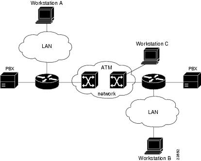
In UNI mode, the user is the router, and the network is an ATM switch. This is an important distinction. The Cisco router does not perform ATM-level call routing. Instead, the ATM switch does the ATM call routing, and the router routes packets through the resulting circuit. The router is viewed as the user and the LAN interconnection device at the end of the circuit, and the ATM switch is viewed as the network.
Figure 4-1 illustrates the router position in a basic ATM environment. The router is used primarily to interconnect LANs through an ATM network. Workstation C in Figure 4-1 is connected directly to the destination ATM switch. You can connect not only routers to ATM switches, but also any computer with an ATM interface that conforms to the ATM Forum UNI specification.
Figure 4-1 Basic ATM Environment
To use SVCs, you first configure the PVC that performs SVC call setup and then configure the network service access point address, as described in the following sections:
•![]() Configuring the PVC That Performs SVC Call Setup
Configuring the PVC That Performs SVC Call Setup
•![]() Configuring the Network Service Access Point Address
Configuring the Network Service Access Point Address
For further information on configuring the IMA port adapter for SVCs, refer to the Wide-Area Networking Configuration Guide on Cisco.com.
Configuring the PVC That Performs SVC Call Setup
Unlike X.25 service, which uses in-band signaling (connection establishment done on the same circuit as data transfer), ATM uses out-of-band signaling. One dedicated PVC exists between the router and the ATM switch, over which all SVC call establishment and call termination requests flow. After the call is established, data transfer occurs over the SVC, from router to router. The signaling that accomplishes the call setup and teardown is called Layer 3 signaling or the Q.2931 protocol.
For out-of-band signaling, a signaling PVC must be configured before any SVCs can be set up. In Figure 4-2, a signaling PVC from the source router to the ATM switch is used to set up two SVCs. This is a fully meshed network; workstations A, B, and C all can communicate with one other.
Figure 4-2 One or More SVCs Require a Signaling PVC

To configure the signaling PVC for all SVC connections, use the atm pvc command in interface configuration mode.
Note ![]() This signaling PVC can be set up on a major interface only, not on the subinterfaces.
This signaling PVC can be set up on a major interface only, not on the subinterfaces.
The VPI and VCI values must be configured to be consistent with those of the local switch. The standard value of VPI is 0; the standard value of VCI is 5.
Configuring the Network Service Access Point Address
Every ATM interface involved with signaling must be configured with a network service access point (NSAP) address. The NSAP address is the ATM address of the interface and must be unique across the network.
You can do one of the following to configure an NSAP address:
•![]() Configure the entire NSAP address manually.
Configure the entire NSAP address manually.
•![]() Configure the ESI and Selector fields.
Configure the ESI and Selector fields.
To configure the ESI and Selector fields, you must also configure a PVC to communicate with the switch through ILMI. The switch then provides the Prefix field of the NSAP address.
Configuring the Complete NSAP Address Manually
When you configure the ATM NSAP address manually, you must enter the entire address in hexadecimal format; that is, each digit entered represents a hexadecimal digit. To represent the complete NSAP address, you must enter 40 hexadecimal digits in the following format:
XX.XXXX.XX.XXXXXX.XXXX.XXXX.XXXX.XXXX.XXXX.XXXX.XX
Note ![]() All ATM NSAP addresses must be entered in the dotted hexadecimal format shown, which conforms to the UNI specification.
All ATM NSAP addresses must be entered in the dotted hexadecimal format shown, which conforms to the UNI specification.
Because the interface has no default NSAP address, you must configure the NSAP address for SVCs. To set the ATM interface's source NSAP address, use the atm nsap-address command in interface configuration mode.
The following is an example of an NSAP address assigned to ATM interface 4/0 on a Cisco 7200 series router:
Router(config-if)# interface atm 4/0
Router(config-if)# atm nsap-address AB.CDEF.01.234567.890A.BCDE.F012.3456.7890.1234.12
You can display the ATM address for the interface by executing the show interfaces atm command.
Configuring the ESI and Selector Fields
You can configure the router to get the NSAP address prefix from the switch; however, the switch must be capable of delivering the NSAP address prefix to the router through ILMI, and the router must be configured with a PVC for communication with the switch through ILMI.
To configure the router to get the NSAP prefix from the switch and use locally entered values for the remaining fields of the address, complete the following tasks in interface configuration mode:
Step 1 ![]() Configure a PVC for communicating with the switch through ILMI:
Configure a PVC for communicating with the switch through ILMI:
Router(config-if)# atm pvc vcd 0 16 ilmi
Step 2 ![]() Enter the ESI and Selector fields of the NSAP address:
Enter the ESI and Selector fields of the NSAP address:
Router(config-if)# atm esi-address esi.selector
where:
•![]() the esi argument is 6 hexadecimal bytes long (12 digits)
the esi argument is 6 hexadecimal bytes long (12 digits)
•![]() the selector argument is 1 hexadecimal byte long (2 digits)
the selector argument is 1 hexadecimal byte long (2 digits)
In the following example on a Cisco 7200 series router, the ESI and Selector field values are assigned, and the ILMI PVC is set up:
Router(config-if)# interface atm 4/0
Router(config-if)# atm pvc 2 0 16 ilmi
Router(config-if)# atm esi-address 345678901234.12
Configuring Classical IP and ARP over ATM
Cisco implements both the ATM Address Resolution Protocol (ARP) server and ATM ARP client functions described in RFC 1577. RFC 1577 models an ATM network as a logical IP subnetwork on a LAN.
The tasks required to configure classical IP and ARP over ATM depend on whether the environment uses SVCs or PVCs. For further information, refer to the Wide-Area Networking Configuration Guide on Cisco.com.
Checking the Configuration
After configuring the new interface, use the show commands to display the status of the new interface or all interfaces, and use the ping and loopback commands to check connectivity. This section includes the following subsections:
•![]() Using show commands to Verify the New Interface Status
Using show commands to Verify the New Interface Status
•![]() Using the ping Command to Verify Network Connectivity
Using the ping Command to Verify Network Connectivity
•![]() Checking Bit Errors Using a Bit Error Rate Test
Checking Bit Errors Using a Bit Error Rate Test
Using show commands to Verify the New Interface Status
Table 4-5 demonstrates how you can use the show commands to verify that new interfaces are configured and operating correctly and that the PA-A3-IMA appears in them correctly. Sample displays of the output of selected show commands appear in the sections that follow. Table 4-6 demonstrates how you can use the ATM show commands to verify the current state of the ATM network and connected virtual circuits. For complete command descriptions and examples, refer to the publications listed in the "Related Documentation" section on page ii.
If an interface is shut down and you configured it as up, or if the displays indicate that the hardware is not functioning properly, ensure that the interface is properly connected and terminated. If you still have problems bringing up the interface, contact a service representative for assistance. This section includes the following subsections:
•![]() Using the show version or show hardware Commands
Using the show version or show hardware Commands
•![]() Using the show interfaces Command
Using the show interfaces Command
•![]() Using the show ima interfaces atm Command to Display IMA Group Information
Using the show ima interfaces atm Command to Display IMA Group Information
Using the show version or show hardware Commands
Display the configuration of the system hardware, the number of each interface type installed, the Cisco IOS software version, the names and sources of configuration files, and the boot images, using the show version (or show hardware) command.
Note ![]() The outputs that appear in this document may not match the output you receive when running these commands. The outputs in this document are examples only.
The outputs that appear in this document may not match the output you receive when running these commands. The outputs in this document are examples only.
The following sections provide platform-specific output examples using the show version command:
•![]() Cisco 7100 Series Routers—Example Output of the show version Command
Cisco 7100 Series Routers—Example Output of the show version Command
•![]() Cisco 7200 Series Routers and Cisco 7200 VXR Routers—Example Output of the show version Command
Cisco 7200 Series Routers and Cisco 7200 VXR Routers—Example Output of the show version Command
•![]() Cisco 7201 Router—Example Output of the show version Command
Cisco 7201 Router—Example Output of the show version Command
•![]() Cisco 7401ASR Router—Example Output of the show version Command
Cisco 7401ASR Router—Example Output of the show version Command
•![]() VIP in Cisco 7500 Series Routers—Example Output of the show version Command
VIP in Cisco 7500 Series Routers—Example Output of the show version Command
•![]() FlexWAN Module—Example Output of the show version Command
FlexWAN Module—Example Output of the show version Command
Cisco 7100 Series Routers—Example Output of the show version Command
Following is an example of the show version command from a Cisco 7100 series router with a PA-A3-IMA installed:
Router# show version
Cisco Internetwork Operating System Software
IOS (tm) EGR Software (C7100-JS-M), Version 12.0(6)XE
Copyright (c) 1986-1999 by cisco Systems, Inc.
Compiled Tue 07-Sep-99 21:42 by rs
Image text-base:0x60008900, data-base:0x61360000
ROM:System Bootstrap, Version 12.0(6)XE [100]RELEASE SOFTWARE
BOOTFLASH:EGR Software (c7100-BOOT-M), Version 12.0(6)XE (fc1)
Router uptime is 10 hours 32 minutes
System returned to ROM by power-on
System image file is "c7100-js-mz"
cisco 7140-2MM3 (EGR) processor with 61440K/69632K bytes of memory.
R7000 CPU at 262Mhz, Implementation 39, Rev 1.0, 256KB L2, 2048KB L3 Cache
Last reset from power-on
Bridging software.
X.25 software, Version 3.0.0.
SuperLAT software (copyright 1990 by Meridian Technology Corp).
TN3270 Emulation software.
2 FastEthernet/IEEE 802.3 interface(s)
11 ATM network interface(s)
125K bytes of non-volatile configuration memory.
16384K bytes of Flash PCMCIA card at slot 0 (Sector size 128K).
8192K bytes of Flash internal SIMM (Sector size 256K).
Configuration register is 0x0
Cisco 7200 Series Routers and Cisco 7200 VXR Routers—Example Output of the show version Command
Following is an example of the show version command from a Cisco 7200 series router with a PA-A3-IMA installed:
Router# show version
Cisco Internetwork Operating System Software
IOS (tm) 7200 Software (C7200-J-M), Version 12.0(5)XE
Copyright (c) 1986-1998 by cisco Systems, Inc.
Compiled Mon 27-Apr-98 16:59 by mwu
Image text-base: 0x600088E0, data-base: 0x6083C000
ROM: System Bootstrap, Version 12.0(5)XE [rson 5], RELEASE SOFTWARE (fc1)
ROM: 7200 Software (C7200-BOOT-M), Release Version 12.0(5)XE [dx5 118]
router uptime is 22 hours, 57 minutes
System restarted by reload at 15:56:03 UTC Tue Apr 28 1998
System image file is "c7200-j-mz.atmdx.0424",
cisco 7206 (NPE200) processor with 57344K/8192K bytes of memory.
R4700 processor, Implementation 33, Revision 1.0 (512KB Level 2 Cache)
Last reset from power-on
Bridging software.
SuperLAT software (copyright 1990 by Meridian Technology Corp).
X.25 software, Version 2.0, NET2, BFE and GOSIP compliant.
TN3270 Emulation software (copyright 1994 by TGV Inc).
4 Ethernet/IEEE 802.3 interfaces.
2 FastEthernet/IEEE 802.3 interfaces.
8 ATM network interfaces.
125K bytes of non-volatile configuration memory.
1024K bytes of packet SRAM memory.
8192K bytes of Flash PCMCIA card at slot 0 (Sector size 128K).
20480K bytes of Flash PCMCIA card at slot 1 (Sector size 128K).
4096K bytes of Flash internal SIMM (Sector size 256K).
Configuration register is 0x0
Cisco 7201 Router—Example Output of the show version Command
Following is an example of the show version command from a Cisco 7201 router:
Router# show version
Cisco IOS Software, 7200 Software (C7200P-ADVENTERPRISEK9-M), Version
12.4(biffDEV.061001), INTERIM SOFTWARE Copyright (c) 1986-2006 by Cisco Systems, Inc.
Compiled Sun 01-Oct-06 23:42 by biff
ROM: System Bootstrap, Version 12.4(4r)XD5, RELEASE SOFTWARE (fc1)
BOOTLDR: Cisco IOS Software, 7200 Software (C7200P-KBOOT-M), Version 12.4(TAZ3DEV.060927),
INTERIM SOFTWARE
c7201alpha1 uptime is 5 days, 18 hours, 32 minutes System returned to ROM by power-on
System image file is "disk0:c7200p-adventerprisek9-mz.2006-10-01.biffdev"
This product contains cryptographic features and is subject to United States and local
country laws governing import, export, transfer and use. Delivery of Cisco cryptographic
products does not imply third-party authority to import, export, distribute or use
encryption.
Importers, exporters, distributors and users are responsible for compliance with U.S. and
local country laws. By using this product you agree to comply with applicable laws and
regulations. If you are unable to comply with U.S. and local laws, return this product
immediately.
A summary of U.S. laws governing Cisco cryptographic products may be found at:
http://www.cisco.com/wwl/export/crypto/tool/stqrg.html
If you require further assistance please contact us by sending email to export@cisco.com.
Cisco 7201 (c7201) processor (revision A) with 917504K/65536K bytes of memory.
Processor board ID 2222222222222
MPC7448 CPU at 1666Mhz, Implementation 0, Rev 2.2
1 slot midplane, Version 2.255
Last reset from power-on
1 FastEthernet interface
4 Gigabit Ethernet interfaces
2045K bytes of NVRAM.
62443K bytes of USB Flash usbflash0 (Read/Write)
250880K bytes of ATA PCMCIA card at slot 0 (Sector size 512 bytes).
65536K bytes of Flash internal SIMM (Sector size 512K).
Configuration register is 0x2
Cisco 7401ASR Router—Example Output of the show version Command
Following is an example of the show version command from a Cisco 7401ASR router with a PA-A3-IMA installed:
Router# show version
Cisco Internetwork Operating System Software
IOS (tm) 7401ASR Software (C7401ASR-J-M), Version 12.0(5)XE
Copyright (c) 1986-1998 by cisco Systems, Inc.
Compiled Mon 27-Apr-98 16:59 by mwu
Image text-base: 0x600088E0, data-base: 0x6083C000
ROM: System Bootstrap, Version 12.0(5)XE [rson 5], RELEASE SOFTWARE (fc1)
ROM: 7401ASR Software (C7401ASR-BOOT-M), Release Version 12.0(5)XE [dx5 118]
router uptime is 22 hours, 57 minutes
System restarted by reload at 15:56:03 UTC Tue Apr 28 1998
System image file is "c7401ASR-j-mz.atmdx.0424",
cisco 7206 (NPE200) processor with 57344K/8192K bytes of memory.
R4700 processor, Implementation 33, Revision 1.0 (512KB Level 2 Cache)
Last reset from power-on
Bridging software.
SuperLAT software (copyright 1990 by Meridian Technology Corp).
X.25 software, Version 2.0, NET2, BFE and GOSIP compliant.
TN3270 Emulation software (copyright 1994 by TGV Inc).
4 Ethernet/IEEE 802.3 interfaces.
2 FastEthernet/IEEE 802.3 interfaces.
8 ATM network interfaces.
125K bytes of non-volatile configuration memory.
1024K bytes of packet SRAM memory.
8192K bytes of Flash PCMCIA card at slot 0 (Sector size 128K).
20480K bytes of Flash PCMCIA card at slot 1 (Sector size 128K).
4096K bytes of Flash internal SIMM (Sector size 256K).
Configuration register is 0x0
VIP in Cisco 7500 Series Routers—Example Output of the show version Command
Following is an example of the show version command from a Cisco 7500 series router with a PA-A3-IMA installed on a VIP2:
Router# show version
Cisco Internetwork Operating System Software
IOS (tm) RSP Software (RSP-JV-M), Version 12.0(5)XE
Copyright (c) 1986-1999 by cisco Systems, Inc.
Compiled Fri 01-Oct-99 18:01 by rs
Image text-base:0x60010908, data-base:0x612E2000
ROM:System Bootstrap, Version 12.0(5) RELEASE SOFTWARE(fc1)
BOOTFLASH:RSP Software (RSP-BOOT-M), Version 12.0(5) [rs]
Router uptime is 1 day, 20 hours, 23 minutes
System returned to ROM by abort at PC 0x602B8BE0
System image file is "rsp-jv-mztest"
cisco RSP4 (R5000) processor with 131072K/2072K bytes of memory.
R5000 CPU at 200Mhz, Implementation 35, Rev 2.1, 512KB L2 Cache
Last reset from power-on
G.703/E1 software, Version 1.0.
G.703/JT2 software, Version 1.0.
X.25 software, Version 3.0.0.
SuperLAT software (copyright 1990 by Meridian Technology Corp).
Bridging software.
TN3270 Emulation software.
Chassis Interface.
1 VIP2 controller (8 ATM).
1 VIP2 R5K controller (4 Ethernet)(9 ATM).
4 Ethernet/IEEE 802.3 interface(s)
17 ATM network interface(s)
123K bytes of non-volatile configuration memory.
8192K bytes of Flash internal SIMM (Sector size 256K).
Configuration register is 0x0
FlexWAN Module—Example Output of the show version Command
Following is an example of the show version command from a Catalyst 6000 family switch with a PA-A3-IMA installed in a FlexWAN module:
Router# show version
Cisco Internetwork Operating System Software
IOS (tm) c6sup2_rp Software (c6sup2_rp-JSV-M), Version 12.1(nightly.E020507) NIHTLY BUILD
Copyright (c) 1986-2002 by cisco Systems, Inc.
Compiled Tue 07-May-02 06:02 by
Image text-base:0x40008980, data-base:0x41830000
ROM:System Bootstrap, Version 12.1(3r)E2, RELEASE SOFTWARE (fc1)
Router uptime is 35 minutes
System returned to ROM by power-on (SP by power-on)
System image file is "sup-bootflash:c6sup22-jsv-mz"
cisco Catalyst 6000 (R7000) processor with 489472K/34816K bytes of memory.
Processor board ID SAD04440003
R7000 CPU at 300Mhz, Implementation 39, Rev 2.1, 256KB L2, 1024KB L3 Cache
Last reset from power-on
Bridging software.
X.25 software, Version 3.0.0.
SuperLAT software (copyright 1990 by Meridian Technology Corp).
TN3270 Emulation software.
1 FlexWAN controller (9 ATM).
1 4-port OC3 POS controller (4 POS).
1 4-port OC12 POS controller (4 POS).
1 Virtual Ethernet/IEEE 802.3 interface(s)
10 Gigabit Ethernet/IEEE 802.3 interface(s)
9 ATM network interface(s)
8 Packet over SONET network interface(s)
381K bytes of non-volatile configuration memory.
16384K bytes of Flash internal SIMM (Sector size 512K).
Configuration register is 0x2
Using the show diag Command
Display the types of port adapters installed in your system (and specific information about each) using the show diag slot command, where slot is the port adapter slot in the Cisco 7100 series routers, Cisco 7200 series routers, Cisco 7200 VXR routers, Cisco 7201 router, Cisco 7301 router, and Cisco 7401ASR router, the module slot in a Cisco 7304 PCI Port Adapter Carrier Card in a Cisco 7304 router, and the interface processor slot in Cisco 7500 series routers with a VIP. In the FlexWAN module, the show diag command is used without the slot designation.
Note ![]() The outputs that appear in this document may not match the output you receive when running these commands. The outputs in this document are examples only.
The outputs that appear in this document may not match the output you receive when running these commands. The outputs in this document are examples only.
The following sections provide platform-specific output examples using the show diag command:
•![]() Cisco 7100 Series Routers—Example Output of the show diag Command
Cisco 7100 Series Routers—Example Output of the show diag Command
•![]() Cisco 7200 Series Routers and Cisco 7200 VXR Routers—Example Output of the show diag Command
Cisco 7200 Series Routers and Cisco 7200 VXR Routers—Example Output of the show diag Command
•![]() Cisco 7201 Router—Example Output of the show diag Command
Cisco 7201 Router—Example Output of the show diag Command
•![]() Cisco 7401ASR Router—Example Output of the show diag Command
Cisco 7401ASR Router—Example Output of the show diag Command
•![]() VIP in Cisco 7500 Series Routers—Example Output of the show diag Command
VIP in Cisco 7500 Series Routers—Example Output of the show diag Command
•![]() FlexWAN Module—Example Output of the show diag Command
FlexWAN Module—Example Output of the show diag Command
Cisco 7100 Series Routers—Example Output of the show diag Command
Following is an example of the show diag command that shows a a PA-A3-IMA in port adapter slot 4 of a Cisco 7140 series router:
Router# show diag 4
Slot 4:
IMA WAN DS1 Port adapter, 8 ports
Port adapter is analyzed
Port adapter insertion time 00:04:23 ago
EEPROM contents at hardware discovery:
Hardware revision 1.0 Board revision UNKNOWN
Serial number 11560312 Part number 73-3614-01
Test history 0x0 RMA number 00-00-00
EEPROM format version 1
EEPROM contents (hex):
0x20:01 BA 01 00 00 B0 65 78 49 0E 1E 01 00 00 00 00
0x30:04 00 00 00 99 02 17 00 FF FF FF FF FF FF FF FF
Note ![]() To use the show diag command with the Cisco 7120 series router, replace the slot argument 4 with 3.
To use the show diag command with the Cisco 7120 series router, replace the slot argument 4 with 3.
Cisco 7200 Series Routers and Cisco 7200 VXR Routers—Example Output of the show diag Command
Following is an example of the show diag command that shows a PA-A3-IMA in port adapter slot 1 of a Cisco 7200 series router:
Router# show diag 1
Slot 1:
IMA WAN DS1 port adapter, 8 ports
Port adapter is analyzed
Port adapter insertion time 1d15h ago
EEPROM contents at hardware discovery:
Hardware revision 1.0 Board revision UNKNOWN
Serial number 10972436 Part number 73-3614-01
Test history 0x0 RMA number 00-00-00
EEPROM format version 1
EEPROM contents (hex):
0x20: 01 BA 01 00 00 A7 6D 14 49 0E 1E 01 00 00 00 00
0x30: 05 00 00 00 98 11 05 00 FF FF FF FF FF FF FF FF
Cisco 7201 Router—Example Output of the show diag Command
Following is an example of the show diag command from a Cisco 7201 router:
Router# show diag 1
Slot 1:
Dual OC3 POS Port adapter, 2 ports
Port adapter is analyzed
Port adapter insertion time 00:02:19 ago
EEPROM contents at hardware discovery:
Hardware Revision : 1.0
PCB Serial Number : JAE07520DYL
Part Number : 73-8220-02
Board Revision : A0
RMA Test History : 00
RMA Number : 0-0-0-0
RMA History : 00
Deviation Number : 0
Product (FRU) Number : PA-POS-2OC3
Top Assy. Part Number : 800-21857-02
EEPROM format version 4
EEPROM contents (hex):
0x00: 04 FF 40 03 E3 41 01 00 C1 8B 4A 41 45 30 37 35
0x10: 32 30 44 59 4C 82 49 20 1C 02 42 41 30 03 00 81
0x20: 00 00 00 00 04 00 88 00 00 00 00 CB 94 50 41 2D
0x30: 50 4F 53 2D 32 4F 43 33 20 20 20 20 20 20 20 20
0x40: 20 C0 46 03 20 00 55 61 02 FF FF FF FF FF FF FF
0x50: FF FF FF FF FF FF FF FF FF FF FF FF FF FF FF FF
0x60: FF FF FF FF FF FF FF FF FF FF FF FF FF FF FF FF
0x70: FF FF FF FF FF FF FF FF FF FF FF FF FF FF FF FF
Cisco 7401ASR Router—Example Output of the show diag Command
Following is an example of the show diag command that shows a PA-A3-IMA in port adapter slot 1 of a Cisco 7401ASR router:
Router# show diag 1
Slot 1:
IMA WAN DS1 port adapter, 8 ports
Port adapter is analyzed
Port adapter insertion time 1d15h ago
EEPROM contents at hardware discovery:
Hardware revision 1.0 Board revision UNKNOWN
Serial number 10972436 Part number 73-3614-01
Test history 0x0 RMA number 00-00-00
EEPROM format version 1
EEPROM contents (hex):
0x20: 01 BA 01 00 00 A7 6D 14 49 0E 1E 01 00 00 00 00
0x30: 05 00 00 00 98 11 05 00 FF FF FF FF FF FF FF FF
VIP in Cisco 7500 Series Routers—Example Output of the show diag Command
Following is an example of the show diag command that shows a PA-A3-IMA in port adapter slot 0 on a VIP2 in interface processor slot 4:
Router# show diag 4
Slot 4:
Physical slot 4, ~physical slot 0xB, logical slot 4, CBus 0
Microcode Status 0x4
Master Enable, LED, WCS Loaded
Board is analyzed
Pending I/O Status:None
EEPROM format version 1
VIP2 controller, HW rev 2.11, board revision C0
Serial number:11208804 Part number:73-1684-04
Test history:0x00 RMA number:00-00-00
Flags:cisco 7000 board; 7500 compatible
FlexWAN Module—Example Output of the show diag Command
Following is an example of the show diag command that shows a PA-A3-IMA in a FlexWAN module:
Router# show diag
Slot 4:Logical_index 8
FlexWan controller
Board is analyzed ipc ready
HW rev 1.0, board revision A01
Serial Number: Part number:73-3921-01
Slot database information:
Flags:0x2004 Insertion time:0xFD790 (00:20:50 ago)
Controller Memory Size:
56 MBytes CPU Memory
8 MBytes Packet Memory
64 MBytes Total on Board SDRAM
IOS (tm) cwlc Software (cwpa-DW-M), Version 12.1(nightly.E020507) NIGHTLY BUILD
PA Bay 0 Information:
IMA DS1 PA, 8 ports
EEPROM format version 1
HW rev 1.00, Board revision 82
Serial number:14076108 Part number:73-3614-02
Using the show interfaces Command
Display status information (including the physical slot and interface address) for the interfaces you specify using the show interfaces command.
Note ![]() The outputs that appear in this document may not match the output you receive when running these commands. The outputs in this document are examples only.
The outputs that appear in this document may not match the output you receive when running these commands. The outputs in this document are examples only.
The following sections provide platform-specific output examples using the show interfaces command:
•![]() Cisco 7100 Series Routers—Example Output of the show interfaces Command
Cisco 7100 Series Routers—Example Output of the show interfaces Command
•![]() Cisco 7200 Series Routers and Cisco 7200 VXR Routers—Example Output of the show interfaces Command
Cisco 7200 Series Routers and Cisco 7200 VXR Routers—Example Output of the show interfaces Command
•![]() Cisco 7201 Router—Example Output of the show interfaces Command
Cisco 7201 Router—Example Output of the show interfaces Command
•![]() Cisco 7401ASR Router—Example Output of the show interfaces Command
Cisco 7401ASR Router—Example Output of the show interfaces Command
•![]() VIP in Cisco 7500 Series Routers—Example Output of the show interfaces Command
VIP in Cisco 7500 Series Routers—Example Output of the show interfaces Command
•![]() FlexWAN Module—Example Output of the show interfaces Command
FlexWAN Module—Example Output of the show interfaces Command
Cisco 7100 Series Routers—Example Output of the show interfaces Command
Following is an example of the show interfaces atm command from a Cisco 7140 series router:
Router# show interfaces ATM4/0
ATM4/0 is down, line protocol is down
Hardware is IMA PA
MTU 4470 bytes, BW 1544 Kbit, DLY 100 usec,
reliability 0/255, txload 1/255, rxload 1/255
Encapsulation UNKNOWN, loopback not set
Keepalive set (10 sec)
Encapsulation(s):AAL5
512 maximum active VCs, 0 current VCCs
VC idle disconnect time:300 seconds
0 carrier transitions
Last input never, output never, output hang never
Last clearing of "show interface" counters never
Input queue:0/75/0 (size/max/drops); Total output drops:0
Queueing strategy:weighted fair
Output queue:0/1000/64/0 (size/max total/threshold/drops)
Conversations 0/0/256 (active/max active/max total)
Reserved Conversations 0/0 (allocated/max allocated)
5 minute input rate 0 bits/sec, 0 packets/sec
5 minute output rate 0 bits/sec, 0 packets/sec
0 packets input, 0 bytes, 0 no buffer
Received 0 broadcasts, 0 runts, 0 giants, 0 throttles
0 input errors, 0 CRC, 0 frame, 0 overrun, 0 ignored, 0 abort
0 packets output, 0 bytes, 0 underruns
0 output errors, 0 collisions, 0 interface resets
0 output buffer failures, 0 output buffers swapped out
Note ![]() To use the show interfaces command with the Cisco 7120 series router, replace the interface address arguments with the slot arguments 3/0, 3/1, 3/2, 3/3, 3/4, 3/5, 3/6,and 3/7.
To use the show interfaces command with the Cisco 7120 series router, replace the interface address arguments with the slot arguments 3/0, 3/1, 3/2, 3/3, 3/4, 3/5, 3/6,and 3/7.
Cisco 7200 Series Routers and Cisco 7200 VXR Routers—Example Output of the show interfaces Command
Following is an example of the show interfaces atm command from a Cisco 7200 series router. In this example, the eight ATM interfaces (0-7) are on a PA-A3-IMA in port adapter slot 4.
Router# show interfaces atm 1/4
ATM1/4 is up, line protocol is down
Hardware is IMA PA
Internet address is 192.168.0.0/24
MTU 4470 bytes, BW 1536 Kbit, DLY 20000 usec,
reliablility 255/255, txload 1/255, rxload 1/255
Encapsulation UNKNOWN, loopback not set
Keepalive set (10 sec)
Encapsulation(s):AAL5
512 maximum active VCs, 0 current VCCs
VC idle disconnect time:300 seconds
2 carrier transitions
Last input never, output never, output hang never
Last clearing of "show interface" counters never
Input queue:0/75/0 (size/max/drops); Total output drops:0
Queueing strategy:weighted fair
Output queue:0/1000/64/0 (size/max total/threshold/drops)
Conversations 0/0/256 (active/max active/max total)
Reserved Conversations 0/0 (allocated/max allocated)
5 minute input rate 0 bits/sec, 0 packets/sec
5 minute output rate 0 bits/sec, 0 packets/sec
0 packets input, 0 bytes, 0 no buffer
Received 0 broadcasts, 0 runts, 0 giants, 0 throttles
0 input errors, 0 CRC, 0 frame, 0 overrun, 0 ignored, 0 abort
0 packets output, 0 bytes, 0 underruns
0 output errors, 0 collisions, 0 interface resets
0 output buffer failures, 0 output buffers swapped out
Cisco 7201 Router—Example Output of the show interfaces Command
Following is an example of the show interfaces command from a Cisco 7201 router:
Router# show interfaces
GigabitEthernet0/0 is up, line protocol is up
Hardware is MV64460 Internal MAC, address is 0019.56c5.2adb (bia
0019.56c5.2adb)
Internet address is 209.165.200.225
MTU 1500 bytes, BW 1000000 Kbit, DLY 10 usec,
reliability 255/255, txload 1/255, rxload 45/255
Encapsulation ARPA, loopback not set
Keepalive set (10 sec)
Full-duplex, 1000Mb/s, media type is RJ45
output flow-control is XON, input flow-control is XON
ARP type: ARPA, ARP Timeout 04:00:00
Last input 00:07:03, output 00:00:07, output hang never
Last clearing of "show interface" counters 00:00:04
Input queue: 0/75/0/0 (size/max/drops/flushes); Total output drops: 0
Queueing strategy: fifo
Output queue: 0/40 (size/max)
5 minute input rate 180240000 bits/sec, 430965 packets/sec
5 minute output rate 0 bits/sec, 0 packets/sec
2222975 packets input, 133378500 bytes, 0 no buffer
Received 0 broadcasts, 0 runts, 0 giants, 0 throttles
0 input errors, 0 CRC, 0 frame, 0 overrun, 0 ignored
0 watchdog, 0 multicast, 0 pause input
0 input packets with dribble condition detected
0 packets output, 0 bytes, 0 underruns
0 output errors, 0 collisions, 0 interface resets
0 babbles, 0 late collision, 0 deferred
0 lost carrier, 0 no carrier, 0 pause output
0 output buffer failures, 0 output buffers swapped out
Cisco 7401ASR Router—Example Output of the show interfaces Command
Following is an example of the show interfaces atm command from a Cisco 7401ASR router. In this example, the eight ATM interfaces (0-7) are on a PA-A3-IMA in port adapter slot 4.
Router# show interfaces atm 1/4
ATM1/4 is up, line protocol is down
Hardware is IMA PA
Internet address is 192.168.0.0/24
MTU 4470 bytes, BW 1536 Kbit, DLY 20000 usec,
reliablility 255/255, txload 1/255, rxload 1/255
Encapsulation UNKNOWN, loopback not set
Keepalive set (10 sec)
Encapsulation(s):AAL5
512 maximum active VCs, 0 current VCCs
VC idle disconnect time:300 seconds
2 carrier transitions
Last input never, output never, output hang never
Last clearing of "show interface" counters never
Input queue:0/75/0 (size/max/drops); Total output drops:0
Queueing strategy:weighted fair
Output queue:0/1000/64/0 (size/max total/threshold/drops)
Conversations 0/0/256 (active/max active/max total)
Reserved Conversations 0/0 (allocated/max allocated)
5 minute input rate 0 bits/sec, 0 packets/sec
5 minute output rate 0 bits/sec, 0 packets/sec
0 packets input, 0 bytes, 0 no buffer
Received 0 broadcasts, 0 runts, 0 giants, 0 throttles
0 input errors, 0 CRC, 0 frame, 0 overrun, 0 ignored, 0 abort
0 packets output, 0 bytes, 0 underruns
0 output errors, 0 collisions, 0 interface resets
0 output buffer failures, 0 output buffers swapped out
VIP in Cisco 7500 Series Routers—Example Output of the show interfaces Command
Following is an example of the show interfaces atm command from a VIP2. In this example, the ATM interface (5) is on a port adapter in port adapter slot 1 of a VIP2 in interface processor slot 4.
Router# show interfaces atm 4/1/5
ATM4/1/5 is up, line protocol is up
Hardware is cyBus IMA PA
Internet address is 10.0.0.3/24
MTU 4470 bytes, sub MTU 4470, BW 1920 Kbit, DLY 20000 usec,
reliability 255/255, txload 1/255, rxload 1/255
Encapsulation ATM, loopback not set
Keepalive not supported
Encapsulation(s):AAL5
512 maximum active VCs, 1 current VCCs
VC idle disconnect time:300 seconds
1 carrier transitions
Last input never, output never, output hang never
Last clearing of "show interface" counters never
Queueing strategy:fifo
Output queue 0/40, 0 drops; input queue 0/75, 0 drops
5 minute input rate 0 bits/sec, 0 packets/sec
5 minute output rate 0 bits/sec, 0 packets/sec
0 packets input, 0 bytes, 0 no buffer
Received 0 broadcasts, 0 runts, 0 giants, 0 throttles
0 input errors, 0 CRC, 0 frame, 0 overrun, 0 ignored, 0 abort
0 packets output, 0 bytes, 0 underruns
0 output errors, 0 collisions, 0 interface resets
0 output buffer failures, 0 output buffers swapped out
FlexWAN Module—Example Output of the show interfaces Command
Following is an example of the show interfaces atm command from a FlexWAN module. In this example, the ATM-configured FlexWAN module is in module slot 8, in port adapter bay 0.
Router# show interfaces atm4/0/ima1
ATM4/0/ima1 is up, line protocol is up
Hardware is IMA PA T1
Internet address is 100.0.0.1/24
MTU 4470 bytes, sub MTU 4470, BW 6093 Kbit, DLY 100 usec,
reliability 255/255, txload 1/255, rxload 1/255
Encapsulation ATM, loopback not set
Keepalive not supported
Encapsulation(s):AAL5
2048 maximum active VCs, 1 current VCCs
VC idle disconnect time:300 seconds
2 carrier transitions
Last input 00:07:11, output 00:07:11, output hang never
Last clearing of "show interface" counters never
Input queue:0/75/0/0 (size/max/drops/flushes); Total output drops:0
Queueing strategy:fifo
Output queue :0/40 (size/max)
5 minute input rate 0 bits/sec, 0 packets/sec
5 minute output rate 0 bits/sec, 0 packets/sec
7 packets input, 596 bytes, 0 no buffer
Received 0 broadcasts, 0 runts, 0 giants, 0 throttles
0 input errors, 0 CRC, 0 frame, 0 overrun, 0 ignored, 0 abort
7 packets output, 604 bytes, 0 underruns
0 output errors, 0 collisions, 6 interface resets
0 output buffer failures, 0 output buffers swapped out
Using the show ima interfaces atm Command to Display IMA Group Information
Use the show ima interfaces atm slot/ ima group-number command to display all the information specific to an IMA group, as shown in the example below:
Router# show ima interfaces atm 1/ima1
ATM1/ima1 is up, line protocol is up
Hardware is IMA PA
Internet address is 192.168.109.1/24
MTU 4470 bytes, sub MTU 4470, BW 1523 Kbit, DLY 20000 usec,
reliability 255/255, txload 1/255, rxload 1/255
Encapsulation ATM, loopback not set
Keepalive not supported
Encapsulation(s):AAL5
1536 maximum active VCs, 1 current VCCs
VC idle disconnect time:300 seconds
1 carrier transitions
Last input 00:13:56, output 00:13:56, output hang never
Last clearing of "show interface" counters never
Queueing strategy:fifo
Output queue 0/40, 0 drops; input queue 0/75, 0 drops
5 minute input rate 0 bits/sec, 0 packets/sec
5 minute output rate 0 bits/sec, 0 packets/sec
5 packets input, 560 bytes, 0 no buffer
Received 0 broadcasts, 0 runts, 0 giants, 0 throttles
0 input errors, 0 CRC, 0 frame, 0 overrun, 0 ignored, 0 abort
5 packets output, 540 bytes, 0 underruns
0 output errors, 0 collisions, 1 interface resets
0 output buffer failures, 0 output buffers swapped out
Using the ping Command to Verify Network Connectivity
Using the ping command, you can verify that an interface port is functioning properly. This section provides a brief description of this command. Refer to the publications listed in the "Related Documentation" section on page ii for detailed command descriptions and examples.
The ping command sends echo requests out to a remote device at an IP address that you specify. After sending an echo request, the system waits a specified time for the remote device to reply. Each echo reply is displayed as an exclamation point (!) on the console terminal; each request that is not returned before the specified timeout is displayed as a period (.). A series of exclamation points (!!!!!) indicates a good connection; a series of periods (.....) or the messages [timed out] or [failed] indicates that the connection failed.
Following is an example of a successful ping command to a remote device with the address 10.0.0.10:
Router# ping 10.0.0.10 <Return>
Type escape sequence to abort.
Sending 5, 100-byte ICMP Echoes to 10.0.0.10, timeout is 2 seconds:
!!!!!
Success rate is 100 percent (5/5), round-trip min/avg/max = 1/15/64 ms
router#
If the connection fails, verify that you have the correct IP address for the destination and that the device is active (powered on), and repeat the ping command.
Proceed to the next section, "Using loopback Commands," to finish checking network connectivity.
Using loopback Commands
With the loopback test, you can detect and isolate equipment malfunctions by testing the connection between the PA-A3-IMA interface and a remote device such as a modem or a CSU/DSU. The loopback command places an interface in loopback mode, which enables test packets that are generated from the ping command to loop through a remote device. If the packets complete the loop, the connection is good. If not, you can isolate a fault to the remote device in the path of the loopback test.
The PA-A3-IMA supports three basic variations of loopback: diagnostic, local, and remote. Diagnostic variation loops the outgoing transmit signal back to incoming receive. Local loopback loops the incoming receive signal back out the transmitter. Remote loopback attempts to set the far end of the T1 interface into loopback mode.
Note ![]() E1 does not support remote loopback.
E1 does not support remote loopback.
Depending on the mode of the port, issuing the loopback command checks the following path:
•![]() When no compact serial cable is attached to the PA-A3-IMA interface port, or if a DCE cable is attached to a port that is configured as line protocol up, the loopback command tests the path between the network processing engine and the interface port only (without leaving the network processing engine and port adapter.)
When no compact serial cable is attached to the PA-A3-IMA interface port, or if a DCE cable is attached to a port that is configured as line protocol up, the loopback command tests the path between the network processing engine and the interface port only (without leaving the network processing engine and port adapter.)
•![]() When a DTE cable is attached to the port, the loopback command tests the path between the network processing engine and the near (network processing engine) side of the DSU or modem to test the PA-A3-IMA interface and compact serial cable.
When a DTE cable is attached to the port, the loopback command tests the path between the network processing engine and the near (network processing engine) side of the DSU or modem to test the PA-A3-IMA interface and compact serial cable.
Checking Bit Errors Using a Bit Error Rate Test
To check bit errors using a bit error rate test (BERT), use the following command:
interface atm1/0 bert pattern
{2^11 | 2^15 | 2^20 O.153 | 2^20 QRSS | 2^23 | 0s | 1s | alt-0-1} interval minutes
where
2^11 is an exponential number that represents a pseudorandom repeating pattern that is 2048 bits long
2^15 is an exponential number that represents a pseudorandom repeating pattern that is 32,767 bits long
2^20 is a pseudorandom repeating pattern that is 1,048,575 bits long
2^23 is a pseudorandom repeating pattern that is 8,388,607 bits long
0s is a pattern of all zeros (00000000...)
1s is a pattern of all 1s (111111...),
minutes is a value 1-14,400, which designate the time the BERT will run.
To stop the BERT, use the optional no form of the command.
The following example runs a BERT that sends the pseudorandom pattern 2^20 and repeats for 60 minutes:
Router# bert pattern 2^20 interval 60
The following example runs a BERT and then displays the results from a Cisco 7200 series router:
Router# configure terminal
Router(config)# interface atm 1/0
Router(config-if)# bert pattern 2^20 interval 1
Router(config-if)# end
Router# show controller atm 1/0
Interface ATM1/0 is up
Hardware is IMA PA - E1 (2Mbps)
Lane client mac address is 0090.b1f8.e454
Framer is PMC PM7344, SAR is LSI ATMIZER II
Firmware rev:DG01, ATMIZER II rev:3
idb=0x61C03C58, ds=0x61C0B480, vc=0x61C2C860, pa=0x61BF9880
slot 3, unit 1, subunit 0, fci_type 0x00BB, ticks 658
400 rx buffers:size=512, encap=64, trailer=28, magic=4
linecode is HDB3
E1 Framing Mode: crc.4 adM format
LBO (Cablelength) is long gain43 120db
Facility Alarms:
No Alarm
Bert Information:
state :OFF, pattern :2^20
interval :0, result :IN_SYNC
sync count :1, bit errors :0
kbit count :122871
bit errors since last sync :0
kbit count since last sync :122871
Some display text omitted.
The output of show controllers atm command displays several error counters. Table 4-7 lists the error counters and their related information.
Using the debug ATM Commands
The following debug commands are available to aid in solving ATM network problems.
To create a dump of all protocol packets, use the debug atm packet command. The command displays the contents of the Subnetwork Access Protocol/Network Layer Protocol Identifier/Switched Multimegabit Data Service (SNAP/NLPID/SMDS) header followed by the first 40 bytes of a packet in hexadecimal format.
To display ATM errors, use the debug atm errors command. The command displays information from all detected ATM errors, including encapsulation failures and errors during ATM configuration.
To display ATM events, use the debug atm events command. The command displays event changes to the IMA port adapter. The command also shows reset, VC configurations, and PA-A3-IMA configurations.
To display information about OAM cells, use the debug atm oam command. The command displays the contents of OAM cells as they arrive from the network.
After using a debug command, turn off debugging with the no debug command.
 Feedback