Connecting Cisco 2-Port E&M Voice Interface Cards
Available Languages
Table of Contents
Connecting Cisco 2-Port E&M Voice Interface Cards
2-Port E&M Voice Interface Cards
2-Port E&M Voice Interface Card LEDs
Prerequisites for Connecting 2-Port E&M Voice Interface Cards to a Network
Installing a Cisco 2-Port E&M Voice Interface Card
Connecting Cisco 2-Port E&M Voice Interface Cards to a Network
Obtaining Documentation, Obtaining Support, and Security Guidelines
Overview
This document provides an overview of Cisco interface cards and explains how to install the Cisco 2-port E&M voice interface card (VIC3-2E/M). It contains the following sections:
- 2-Port E&M Voice Interface Cards
- Obtaining Documentation, Obtaining Support, and Security Guidelines
For an overview of Cisco interface cards used for Cisco access routers, see the Cisco Interface Cards for Cisco Access Routers document.
2-Port E&M Voice Interface Cards
This section describes E&M voice interface cards and how to them to a network. It contains the following sections:
- 2-Port E&M Voice Interface Card LEDs
- Supported Platforms
- Prerequisites for Connecting 2-Port E&M Voice Interface Cards to a Network
- Connecting Cisco 2-Port E&M Voice Interface Cards to a Network
Cisco voice interface cards (VICs) support voice technologies. VICs can be installed in interface card slots on supported Cisco access routers or in 1- or 2-slot voice network modules that are installed in network module slots on supported Cisco access routers.
RecEive and transMit (E&M) is a signaling technique for 2-wire and 4-wire telephone and trunk interfaces. The E&M interface typically connects remote calls from an IP network to a PBX. The Cisco
2-port E&M voice interface card is shown in Figure 1.Figure 1 Cisco 2-Port E&M VIC Front Panel (VIC3-2E/M)
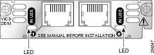
2-Port E&M Voice Interface Card LEDs
The E&M voice interface card has one IN USE LED for each port. Table 1 describes the functions of the LEDs.
Supported Platforms
This Cisco voice interface card (VIC3-2E/M) is supported on the following Cisco routers:
- Cisco 2800 series routers, including the Cisco 2801, Cisco 2811, Cisco 2821, and Cisco 2851
- Cisco 3800 series routers, including the Cisco 3825 and Cisco 3845
- Cisco IAD2430 series routers
- Cisco 2900 series routers
- Cisco 3900 series routers

Note
Use Cisco Feature Navigator to find information about platform support and Cisco IOS software image support. Access Cisco Feature Navigator at http://www.cisco.com/go/fn. You must have an account on Cisco.com. If you do not have an account or have forgotten your username or password, click Cancel at the login dialog box and follow the instructions that appear.
Prerequisites for Connecting 2-Port E&M Voice Interface Cards to a Network
Before connecting a VIC to the network, ensure that the VIC is installed in the router, the equipment is properly grounded, and you have the proper cables for connecting the VIC to the network. This section describes the preparation necessary before connecting a 2-port E&M VIC to the network.
Installing a Cisco 2-Port E&M Voice Interface Card
Install the Cisco 2-port E&M VIC according to the instructions in Installing Cisco Interface Cards in Cisco Access Routers.
Grounding
Ensure that the equipment you are working with is properly grounded according to the instructions in Installing Cisco Interface Cards in Cisco Access Routers .
Cables
Use a straight-through RJ-48C cable to connect the E&M card to the PSTN or PBX through a telephone wall outlet.

Note
Connecting Cisco 2-Port E&M Voice Interface Cards to a Network
To connect the Cisco 2-port E&M VIC, follow these steps:
Step 1
Caution
Step 2
Figure 2 Cisco 2-Port E&M VIC Front Panel (VIC3-2E/M)

Step 3
The following warning applies to routers that use a DC power supply:

Warning
Obtaining Documentation, Obtaining Support, and Security Guidelines
For information on obtaining documentation, obtaining support, providing documentation feedback, security guidelines, and also recommended aliases and general Cisco documents, see the monthly What’s New in Cisco Product Documentation, which also lists all new and revised Cisco technical documentation, at:
http://www.cisco.com/en/US/docs/general/whatsnew/whatsnew.html
Cisco and the Cisco logo are trademarks or registered trademarks of Cisco and/or its affiliates in the U.S. and other countries. To view a list of Cisco trademarks, go to this URL: www.cisco.com/go/trademarks. Third-party trademarks mentioned are the property of their respective owners. The use of the word partner does not imply a partnership relationship between Cisco and any other company. (1110R)
 Feedback