Contents
- Configuring STP Extensions Using NX-OS
- Information About STP Extensions
- STP Port Types
- STP Edge Ports
- Bridge Assurance
- BPDU Guard
- BPDU Filtering
- Loop Guard
- Root Guard
- Applying STP Extension Features
- PVST Simulation
- High Availability for STP
- Virtualization Support for STP Extensions
- Licensing Requirements for STP Extensions
- Prerequisites for STP Extensions
- Guidelines and Limitations for Configuring STP Extensions
- Configuring STP Extensions Steps
- Configuring Spanning Tree Port Types Globally
- Configuring Spanning Tree Edge Ports on Specified Interfaces
- Configuring Spanning Tree Network Ports on Specified Interfaces
- Enabling BPDU Guard Globally
- Enabling BPDU Guard on Specified Interfaces
- Enabling BPDU Filtering Globally
- Enabling BPDU Filtering on Specified Interfaces
- Enabling Loop Guard Globally
- Enabling Loop Guard or Root Guard on Specified Interfaces
- Configuring PVST Simulation Globally-CLI Version
- Configuring PVST Simulation Per Port
- Verifying the STP Extension Configuration
- STP Extension Example Configuration
- Default Settings for STP Extensions
- Additional References for STP Extensions -- CLI Version
- Feature History for Configuring STP Extensions -- CLI version
Configuring STP Extensions Using NX-OS
This chapter describes how to configure Spanning Tree Protocol (STP) extensions on Cisco Nexus 7000 Series devices.
- Information About STP Extensions
- Licensing Requirements for STP Extensions
- Prerequisites for STP Extensions
- Guidelines and Limitations for Configuring STP Extensions
- Configuring STP Extensions Steps
- Verifying the STP Extension Configuration
- STP Extension Example Configuration
- Default Settings for STP Extensions
- Additional References for STP Extensions -- CLI Version
- Feature History for Configuring STP Extensions -- CLI version
- STP Port Types
- Bridge Assurance
- BPDU Guard
- BPDU Filtering
- Loop Guard
- Root Guard
- Applying STP Extension Features
- PVST Simulation
- High Availability for STP
- Virtualization Support for STP Extensions
- Configuring Spanning Tree Port Types Globally
- Configuring Spanning Tree Edge Ports on Specified Interfaces
- Configuring Spanning Tree Network Ports on Specified Interfaces
- Enabling BPDU Guard Globally
- Enabling BPDU Guard on Specified Interfaces
- Enabling BPDU Filtering Globally
- Enabling BPDU Filtering on Specified Interfaces
- Enabling Loop Guard Globally
- Enabling Loop Guard or Root Guard on Specified Interfaces
- Configuring PVST Simulation Globally-CLI Version
- Configuring PVST Simulation Per Port
Information About STP Extensions
Note
See the Cisco Nexus 7000 Series NX-OS Interfaces Configuration Guide, Release 4.2 for information on creating Layer 2 interfaces.
Cisco has added extensions to STP that enhances loop prevention, protects against some possible user misconfigurations, and provides better control over the protocol parameters. Although, in some cases, similar functionality may be incorporated into the IEEE 802.1w Rapid Spanning Tree Protocol (RSTP) standard, we recommend using these extensions. All of these extensions, except PVST Simulation, can be used with both Rapid PVST+ and MST. You use PVST Simulation only with MST.
The available extensions are spanning tree edge ports (which supply the functionality previously known as PortFast), Bridge Assurance, BPDU Guard, BPDU Filtering, Loop Guard, Root Guard, and PVT Simulation. Many of these features can be applied either globally or on specified interfaces.
Note
Spanning tree is used to refer to IEEE 802.1w and IEEE 802.1s. If the text is discussing the IEEE 802.1D Spanning Tree Protocol, 802.1D is stated specifically.
- STP Port Types
- Bridge Assurance
- BPDU Guard
- BPDU Filtering
- Loop Guard
- Root Guard
- Applying STP Extension Features
- PVST Simulation
- High Availability for STP
- Virtualization Support for STP Extensions
- STP Edge Ports
STP Port Types
You can configure a spanning tree port as an edge port, a network port, or a normal port. A port can be in only one of these states at a given time. The default spanning tree port type is normal.
Edge ports, which are connected to Layer 2 hosts, can be either an access port or a trunk port.
Note
If you configure a port connected to a Layer 2 switch or bridge as an edge port, you might create a bridging loop.
Network ports are connected only to Layer 2 switches or bridges.
Note
If you mistakenly configure ports that are connected to Layer 2 hosts, or edge devices, as spanning tree network ports, those ports will automatically move into the blocking state.
STP Edge Ports
You connect STP edge ports only to Layer 2 hosts. The edge port interface immediately transitions to the forwarding state, without moving through the blocking or learning states. (This immediate transition was previously configured as the Cisco- proprietary feature PortFast.)
Interfaces that are connected to Layer 2 hosts should not receive STP Bridge Protocol Data Units (BPDUs).
Bridge Assurance
You can use Bridge Assurance to protect against certain problems that can cause bridging loops in the network. Specifically, you use Bridge Assurance to protect against a unidirectional link failure or other software failure and a device that continues to forward data traffic when it is no longer running the spanning tree algorithm.
Note
Bridge Assurance is supported only by Rapid PVST+ and MST.
Bridge Assurance is enabled by default and can only be disabled globally. Also, Bridge Assurance can be enabled only on spanning tree network ports that are point-to-point links. Finally, both ends of the link must have Bridge Assurance enabled. If the device on one side of the link has Bridge Assurance enabled and the device on the other side either does not support Bridge Assurance or does not have this feature enabled, the connecting port is blocked.
With Bridge Assurance enabled, BPDUs are sent out on all operational network ports, including alternate and backup ports, for each hello time period. If the port does not receive a BPDU for a specified period, the port moves into the blocking state and is not used in the root port calculation. Once that port receives a BPDU, it resumes the normal spanning tree transitions.
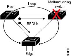
This figure demonstrates a potential network problem when the device fails and you are not running Bridge Assurance.
Figure 2. Network Problem without Running Bridge Assurance
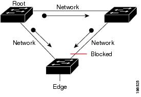
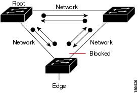
This figure shows the network with Bridge Assurance enabled, and the STP topology progressing normally with bidirectional BPDUs issuing from every STP network port.
Figure 3. Network STP Topology Running Bridge Assurance
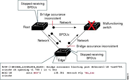
 This figure shows how the potential network problem does not happen when you have Bridge Assurance enabled on your network.
Figure 4. Network Problem Averted with Bridge Assurance Enabled
BPDU Guard
Enabling BPDU Guard shuts down that interface if a BPDU is received.
You can configure BPDU Guard at the interface level. When configured at the interface level, BPDU Guard shuts the port down as soon as the port receives a BPDU, regardless of the port type configuration.
When you configure BPDU Guard globally, it is effective only on operational spanning tree edge ports. In a valid configuration, Layer 2 LAN edge interfaces do not receive BPDUs. A BPDU that is received by an edge Layer 2 LAN interface signals an invalid configuration, such as the connection of an unauthorized device. BPDU Guard, when enabled globally, shuts down all spanning tree edge ports when they receive a BPDU.
BPDU Guard provides a secure response to invalid configurations, because you must manually put the Layer 2 LAN interface back in service after an invalid configuration.
Note
When enabled globally, BPDU Guard applies to all operational spanning tree edge interfaces.
BPDU Filtering
You can use BPDU Filtering to prevent the device from sending or even receiving BPDUs on specified ports.
When configured globally, BPDU Filtering applies to all operational spanning tree edge ports. You should connect edge ports only to hosts, which typically drop BPDUs. If an operational spanning tree edge port receives a BPDU, it immediately returns to a normal spanning tree port type and moves through the regular transitions. In that case, BPDU Filtering is disabled on this port, and spanning tree resumes sending BPDUs on this port.
In addition, you can configure BPDU Filtering by the individual interface. When you explicitly configure BPDU Filtering on a port, that port does not send any BPDUs and drops all BPDUs that it receives. You can effectively override the global BPDU Filtering setting on individual ports by configuring the specific interface. This BPDU Filtering command on the interface applies to the entire interface, whether the interface is trunking or not.
Caution
Use care when configuring BPDU Filtering per interface. If you explicitly configure BPDU Filtering on a port that is not connected to a host, it can result in bridging loops because the port will ignore any BPDU that it receives and go to forwarding.
This table lists all the BPDU Filtering combinations.
Table 1 BPDU Filtering ConfigurationsBPDU Filtering Per Port Configuration
BPDU Filtering Global Configuration
STP Edge Port Configuration
BPDU Filtering State
Default 1
Enable
Enable
Enable 2
Default
Enable
Disable
Disable
Default
Disable
Not applicable
Disable
Disable
Not applicable
Not applicable
Disable
Enable
Not applicable
Not applicable
Enable
1 No explicit port configuration.2 The port transmits at least 10 BPDUs. If this port receives any BPDUs, the port returns to the spanning tree normal port state and BPDU Filtering is disabled.Loop Guard
Loop Guard helps prevent bridging loops that could occur because of a unidirectional link failure on a point-to-point link.
An STP loop occurs when a blocking port in a redundant topology erroneously transitions to the forwarding state. Transitions are usually caused by a port in a physically redundant topology (not necessarily the blocking port) that stops receiving BPDUs.
When you enable Loop Guard globally, it is useful only in switched networks where devices are connected by point-to-point links. On a point-to-point link, a designated bridge cannot disappear unless it sends an inferior BPDU or brings the link down. However, you can enable Loop Guard on shared links per interface,
You can use Loop Guard to determine if a root port or an alternate/backup root port receives BPDUs. If the port that was previously receiving BPDUs is no longer receiving BPDUs, Loop Guard puts the port into an inconsistent state (blocking) until the port starts to receive BPDUs again. If such a port receives BPDUs again, the port—and link—is deemed viable again. The protocol removes the loop-inconsistent condition from the port, and the STP determines the port state because the recovery is automatic.
Loop Guard isolates the failure and allows STP to converge to a stable topology without the failed link or bridge. Disabling Loop Guard moves all loop-inconsistent ports to the listening state.
You can enable Loop Guard on a per-port basis. When you enable Loop Guard on a port, it is automatically applied to all of the active instances or VLANs to which that port belongs. When you disable Loop Guard, it is disabled for the specified ports.
Root Guard
When you enable Root Guard on a port, Root Guard does not allow that port to become a root port. If a received BPDU triggers an STP convergence that makes that designated port become a root port, that port is put into a root-inconsistent (blocked) state. After the port stops sending superior BPDUs, the port is unblocked again. Through STP, the port moves to the forwarding state. Recovery is automatic.
When you enable Root Guard on an interface, this functionality applies to all VLANs to which that interface belongs.
You can use Root Guard to enforce the root bridge placement in the network. Root Guard ensures that the port on which Root Guard is enabled is the designated port. Normally, root bridge ports are all designated ports, unless two or more of the ports of the root bridge are connected. If the bridge receives superior BPDUs on a Root Guard-enabled port, the bridge moves this port to a root-inconsistent STP state. In this way, Root Guard enforces the position of the root bridge.
You cannot configure Root Guard globally.
PVST Simulation
MST interoperates with Rapid PVST+ with no need for user configuration. The PVST simulation feature enables this interoperability.
Note
PVST simulation is enabled by default when you enable MST. By default, all interfaces on the device interoperate between MST and Rapid PVST+.
However, you may want to control the connection between MST and Rapid PVST+ to protect against accidentally connecting an MST-enabled port to a port enabled to run Rapid PVST+. Because Rapid PVST+ is the default STP mode, you may encounter many Rapid PVST+ connections.
Disabling Rapid PVST+ simulation, which can be done per port or globally for the entire device, moves the MST-enabled port to the blocking state once it detects it is connected to a Rapid PVST+-enabled port. This port remains in the inconsistent state until the port stops receiving Rapid PVST+/SSTP BPDUs, and then the port resumes the normal STP transition process.
The root bridge for all STP instances must all be in either the MST region or the Rapid PVST+ side. If the root bridge for all STP instances are not on one side or the other, the software moves the port into a PVST simulation-inconsistent state.
Note
We recommend that you put the root bridge for all STP instances in the MST region.
High Availability for STP
The software supports high availability for STP. However, the statistics and timers are not restored when STP restarts. The timers start again and the statistics begin from 0.
Note
See the Cisco Nexus 7000 Series NX-OS High Availability and Redundancy Guide, Release 4.2 for complete information on high-availability features.
Virtualization Support for STP Extensions
The system provides support for virtual device contexts (VDCs), and each VDC runs a separate STP. You can run Rapid PVST+ in one VDC and MST in another VDC.
Note
See the Cisco Nexus 7000 Series NX-OS Virtual Device Context Configuration Guide, Release 4.2, for complete information on VDCs and assigning resources.
Licensing Requirements for STP Extensions
The following table shows the licensing requirements for this feature:
License Requirement
NX-OS
STP extensions require no license. Any feature not included in a license package is bundled with the Cisco NX-OS system images and is provided at no extra charge to you. For a complete explanation of the NX-OS licensing scheme, see Cisco Nexus 7000 Series NX-OS Licensing Guide, Release 4.2.
However, using VDCs requires an Advanced Services license.
Guidelines and Limitations for Configuring STP Extensions
Follow these guidelines and limitations when configuring STP extensions:
Connect STP network ports only to switches.
You should configure host ports as STP edge ports and not as network ports.
If you enable STP network port types globally, ensure that you manually configure all ports connected to hosts as STP edge ports.
You should configure all access and trunk ports connected to Layer 2 hosts as edge ports.
Bridge Assurance runs only on point-to-point spanning tree network ports. You must configure each side of the link for this feature.
We recommend that you enable Bridge Assurance throughout your network.
We recommend that you enable BPDU Guard on all edge ports.
Enabling Loop Guard globally works only on point-to-point links.
Enabling Loop Guard per interface works on both shared and point-to-point links.
Root Guard forces a port to always be a designated port; it does not allow a port to become a root port. Loop Guard is effective only if the port is a root port or an alternate port. You cannot enable Loop Guard and Root Guard on a port at the same time.
Loop Guard has no effect on a disabled spanning tree instance or a VLAN.
Spanning tree always chooses the first operational port in the channel to send the BPDUs. If that link becomes unidirectional, Loop Guard blocks the channel, even if other links in the channel are functioning properly.
If you group together a set of ports that are already blocked by Loop Guard to form a channel, spanning tree loses all the state information for those ports and the new channel port may obtain the forwarding state with a designated role.
If a channel is blocked by Loop Guard and the channel members go back to an individual link status, spanning tree loses all the state information. The individual physical ports may obtain the forwarding state with the designated role, even if one or more of the links that formed the channel are unidirectional.
Note
You can enable UniDirectional Link Detection (UDLD) aggressive mode to isolate the link failure. A loop may occur until UDLD detects the failure, but Loop Guard will not be able to detect it. See the Cisco Nexus 7000 Series NX-OS Interfaces Configuration Guide, Release 4.2 for information on UDLD.
You should enable Loop Guard globally on a switch network with physical loops.
You should enable Root Guard on ports that connect to network devices that are not under direct administrative control.
Configuring STP Extensions Steps
- Configuring Spanning Tree Port Types Globally
- Configuring Spanning Tree Edge Ports on Specified Interfaces
- Configuring Spanning Tree Network Ports on Specified Interfaces
- Enabling BPDU Guard Globally
- Enabling BPDU Guard on Specified Interfaces
- Enabling BPDU Filtering Globally
- Enabling BPDU Filtering on Specified Interfaces
- Enabling Loop Guard Globally
- Enabling Loop Guard or Root Guard on Specified Interfaces
- Configuring PVST Simulation Globally-CLI Version
- Configuring PVST Simulation Per Port
Configuring Spanning Tree Port Types Globally
The spanning tree port type designation depends on the device the port is connected to, as follows:
Edge—Edge ports are connected to Layer 2 hosts and are access ports.
Network—Network ports are connected only to Layer 2 switches or bridges and can be either access or trunk ports.
Normal—Normal ports are neither edge ports nor network ports; they are normal spanning tree ports. These ports can be connected to any device.
You can configure the port type either globally or per interface. By default, the spanning tree port type is normal.
Before You BeginProcedureBefore you configure the spanning port type, you should do the following:
Ensure that you are in the correct VDC (or enter the switchto vdc command).
Ensure that STP is configured.
Ensure that you are configuring the ports correctly as to the device to which the port is connected.
This example shows how to configure all access ports connected to Layer 2 hosts as spanning tree edge ports:
switch# config t switch(config)#spanning-tree port type edge default switch(config)#exit switch#This example shows how to configure all ports connected to Layer 2 switches or bridges as spanning tree network ports:
switch# config t
switch(config)#spanning-tree port type network default
switch(config)#
Configuring Spanning Tree Edge Ports on Specified Interfaces
You can configure spanning tree edge ports on specified interfaces. Interfaces configured as spanning tree edge ports immediately transition to the forwarding state, without passing through the blocking or learning states, on linkup.
This command has four states:
spanning-tree port type edge—This command explicitly enables edge behavior on the access port.
spanning-tree port type edge trunk—This command explicitly enables edge behavior on the trunk port.
Note
If you enter the spanning-tree port type edge trunk command, the port is configured as an edge port even in the access mode.
spanning-tree port type normal—This command explicitly configures the port as a normal spanning tree port and the immediate transition to the forwarding state is not enabled.
no spanning-tree port type—This command implicitly enables edge behavior if you define the spanning-tree port type edge default command in global configuration mode. If you do not configure the edge ports globally, the no spanning-tree port type command is equivalent to the spanning-tree port type normal command.
Before You BeginProcedureBefore you configure the spanning port type, you should do the following:
Ensure that you are in the correct VDC (or enter the switchto vdc command).
Ensure that STP is configured.
Ensure that you are configuring the ports correctly as to the device to which the port is connected.
Command or Action Purpose Step 1 config t
Example:switch# config t switch(config)#Enters configuration mode.
Step 2 interface type slot/port
Example:switch(config)# interface ethernet 1/4 switch(config-if)#Specifies the interface to configure, and enters the interface configuration mode.
Step 3 spanning-tree port type edge
Example:switch(config-if)# spanning-tree port type edgeConfigures the specified access interfaces to be spanning edge ports. Edge ports immediately transition to the forwarding state without passing through the blocking or learning state at linkup. By default, spanning tree ports are normal port types.
Step 4 exit
Example:switch(config-if)# exit switch(config)#Exits interface configuration mode.
Step 5 show spanning-tree
Example:switch# show spanning-tree(Optional) Displays the STP configuration including the STP port type if configured.
Step 6 copy running-config startup-config
Example:switch# copy running-config startup-config(Optional) Copies the running configuration to the startup configuration.
Configuring Spanning Tree Network Ports on Specified Interfaces
You can configure spanning tree network ports on specified interfaces.
Bridge Assurance runs only on spanning tree network ports.
This command has three states:
spanning-tree port type network—This command explicitly configures the port as a network port. If you enable Bridge Assurance globally, it automatically runs on a spanning tree network port.
spanning-tree port type normal —This command explicitly configures the port as a normal spanning tree port and Bridge Assurance cannot run on this interface.
no spanning-tree port type—This command implicitly enables the port as a spanning tree network port if you define the spanning-tree port type network default command in global configuration mode. If you enable Bridge Assurance globally, it automatically runs on this port.
Note
A port connected to Layer 2 hosts that is configured as a network ports automatically moves into the blocking state.
Before You BeginProcedureBefore you configure the spanning port type, you should do the following:
Ensure that you are in the correct VDC (or enter the switchto vdc command).
Ensure that STP is configured.
Ensure that you are configuring the ports correctly as to the device to which the port is connected.
Command or Action Purpose Step 1 config t
Example:switch# config t switch(config)#Enters configuration mode.
Step 2 interface type slot/port
Example:switch(config)# interface ethernet 1/4 switch(config-if)#Specifies the interface to configure, and enters the interface configuration mode.
Step 3 spanning-tree port type network
Example:switch(config-if)# spanning-tree port type networkConfigures the specified interfaces to be spanning network ports. If you enable Bridge Assurance, it automatically runs on network ports. By default, spanning tree ports are normal port types.
Step 4 exit
Example:switch(config-if)# exit switch(config)#Exits interface configuration mode.
Step 5 show spanning-tree
Example:switch# show spanning-tree(Optional) Displays the STP configuration including the STP port type if configured.
Step 6 copy running-config startup-config
Example:switch# copy running-config startup-config(Optional) Copies the running configuration to the startup configuration.
Enabling BPDU Guard Globally
You can enable BPDU Guard globally by default. In this condition, the system shuts down an edge port that receives a BPDU.
Note
We recommend that you enable BPDU Guard on all edge ports.
Before You BeginProcedureBefore you configure the spanning port type, you should do the following:
Ensure that you are in the correct VDC (or enter the switchto vdc command).
Ensure that STP is configured.
Ensure that you are configuring the ports correctly as to the device to which the port is connected.
Command or Action Purpose Step 1 config t
Example:switch# config t switch(config)#Enters configuration mode.
Step 2 spanning-tree port type edge bpduguard default
Example:switch(config)# spanning-tree port type edge bpduguard defaultEnables BPDU Guard by default on all spanning tree edge ports. By default, global BPDU Guard is disabled.
Step 3 exit
Example:switch(config)# exit switch#Exits configuration mode.
Step 4 show spanning-tree summary
Example:switch# show spanning-tree summary(Optional) Displays summary STP information.
Step 5 copy running-config startup-config
Example:switch# copy running-config startup-config(Optional) Copies the running configuration to the startup configuration.
Enabling BPDU Guard on Specified Interfaces
You can enable BPDU Guard on specified interfaces. Enabling BPDU Guard shuts down the port if it receives a BPDU.
You can configure BPDU Guard on specified interfaces as follows:
spanning-tree bpduguard enable —Unconditionally enables BPDU Guard on the interface.
spanning-tree bpduguard disable —Unconditionally disables BPDU Guard on the interface.
no spanning-tree bpduguard —Enables BPDU Guard on the interface if it is an operational edge port and if the spanning-tree port type edge bpduguard default command is configured.
Before You BeginProcedureBefore you configure this feature, you should do the following:
Ensure that you are in the correct VDC (or enter the switchto vdc command).
Ensure that STP is configured.
Command or Action Purpose Step 1 config t
Example:switch# config t switch(config)#Enters configuration mode.
Step 2 interface type slot/port
Example:switch(config)# interface ethernet 1/4 switch(config-if)#Specifies the interface to configure, and enters the interface configuration mode.
Step 3 Enter one of the following commands:
Option Description spanning-tree bpduguard {enable | disable} Enables or disables BPDU Guard for the specified spanning tree edge interface. By default, BPDU Guard is disabled on the interfaces.
no spanning-tree bpduguard Falls back to the default BPDU Guard global setting that you set for the interfaces by entering the spanning-tree port type edge bpduguard default command.
Example:switch(config-if)# spanning-tree bpduguard enableStep 4 exit
Example:switch(config-if)# exit switch(config)#Exits interface mode.
Step 5 show spanning-tree summary
Example:switch# show spanning-tree summary(Optional) Displays summary STP information.
Step 6 copy running-config startup-config
Example:switch(config)# copy running-config startup-config(Optional) Copies the running configuration to the startup configuration.
Enabling BPDU Filtering Globally
You can enable BPDU Filtering globally by default on spanning tree edge ports.
If an edge port with BPDU Filtering enabled receives a BPDU, it loses its operation status as edge port and resumes the regular STP transitions. However, this port maintains its configuration as an edge port.
Caution
Be careful when using this command. Using this command incorrectly can cause bridging loops.
Before You BeginProcedureBefore you configure this feature, you should do the following:
Ensure that you are in the correct VDC (or enter the switchto vdc command).
Ensure that STP is configured.
Ensure that you have configured some spanning tree edge ports.
Note
When enabled globally, BPDU Filtering is applied only on ports that are operational edge ports. Ports send a few BPDUs at linkup before they effectively filter outbound BPDUs. If a BPDU is received on an edge port, it immediately loses its operational edge port status and BPDU Filtering is disabled.
Command or Action Purpose Step 1 config t
Example:switch# config t switch(config)#Enters configuration mode.
Step 2 spanning-tree port type edge bpdufilter default
Example:switch(config)# spanning-tree port type edge bpdufilter defaultEnables BPDU Filtering by default on all operational spanning tree edge ports. Global BPDU Filtering is disabled by default.
Step 3 exit
Example:switch(config)# exit switch#Exits configuration mode.
Step 4 show spanning-tree summary
Example:switch# show spanning-tree summary(Optional) Displays summary STP information.
Step 5 copy running-config startup-config
Example:switch# copy running-config startup-config(Optional) Copies the running configuration to the startup configuration.
Enabling BPDU Filtering on Specified Interfaces
You can apply BPDU Filtering to specified interfaces. When enabled on an interface, that interface does not send any BPDUs and drops all BPDUs that it receives. This BPDU Filtering functionality applies to the entire interface, whether trunking or not.
Caution
Be careful when you enter the spanning-tree bpdufilter enable command on specified interfaces. Explicitly configuring BPDU Filtering on a port that is not connected to a host can result in bridging loops because the port will ignore any BPDU that it receives and go to forwarding.
You can enter this command to override the port configuration on specified interfaces.
This command has three states:
spanning-tree bpdufilter enable—Unconditionally enables BPDU Filtering on the interface.
spanning-tree bpdufilter disable—Unconditionally disables BPDU Filtering on the interface.
no spanning-tree bpdufilter ——Enables BPDU Filtering on the interface if the interface is in operational edge port and if you configure the spanning-tree port type edge bpdufilter default command.
Before You BeginProcedureBefore you configure this feature, you should do the following:
Ensure that you are in the correct VDC (or enter the switchto vdc command).
Ensure that STP is configured.
Note
When you enable BPDU Filtering locally on a port, this feature prevents the device from receiving or sending BPDUs on this port.
Command or Action Purpose Step 1 config t
Example:switch# config t switch(config)#Enters configuration mode.
Step 2 interface type slot/port
Example:switch(config)# interface ethernet 1/4 switch(config-if)#Specifies the interface to configure, and enters the interface configuration mode.
Step 3 Enter one of the following commands:
Option Description spanning-tree bpdufilter {enable | disable} Enables or disables BPDU Filtering for the specified spanning tree edge interface. By default, BPDU Filtering is disabled.
no spanning-tree bpdufilter Enables BPDU Filtering on the interface if the interface is an operational spanning tree edge port and if you enter the spanning-tree port type edge bpdufilter default command.
Example:switch(config-if)# spanning-tree bpdufilter enableStep 4 exit
Example:switch(config-if)# exit switch(config)#Exits interface mode.
Step 5 show spanning-tree summary
Example:switch# show spanning-tree summary(Optional) Displays summary STP information.
Step 6 copy running-config startup-config
Example:switch(config)# copy running-config startup-config(Optional) Copies the running configuration to the startup configuration.
Enabling Loop Guard Globally
You can enable Loop Guard globally by default on all point-to-point spanning tree normal and network ports. Loop Guard does not run on edge ports.
Loop Guard provides additional security in the bridge network. Loop Guard prevents alternate or root ports from becoming the designated port because of a failure that could lead to a unidirectional link.
Note
Entering the Loop Guard command for the specified interface overrides the global Loop Guard command.
Before You BeginProcedureBefore you configure this feature, you should do the following:
Ensure that you are in the correct VDC (or enter the switchto vdc command).
Ensure that STP is configured.
Ensure that you have spanning tree normal ports or have configured some network ports.
Command or Action Purpose Step 1 config t
Example:switch# config t switch(config)#Enters configuration mode.
Step 2 spanning-tree loopguard default
Example:switch(config)# spanning-tree loopguard defaultEnables Loop Guard by default on all spanning tree normal and network ports. By default, global Loop Guard is disabled.
Step 3 exit
Example:switch(config)# exit switch#Exits configuration mode.
Step 4 show spanning-tree summary
Example:switch# show spanning-tree summary(Optional) Displays summary STP information.
Step 5 copy running-config startup-config
Example:switch# copy running-config startup-config(Optional) Copies the running configuration to the startup configuration.
Enabling Loop Guard or Root Guard on Specified Interfaces
Note
You can run Loop Guard on spanning tree normal or network ports. You can run Root Guard on all spanning tree ports: normal, edge, or network.
You can enable either Loop Guard or Root Guard on specified interfaces.
Enabling Root Guard on a port means that port cannot become a root port, and Loop Guard prevents alternate or root ports from becoming the designated port because of a failure that could lead to a unidirectional link
Both Loop Guard and Root Guard enabled on an interface apply to all VLANs to which that interface belongs.
Note
Entering the Loop Guard command for the specified interface overrides the global Loop Guard command.
Before You BeginProcedureBefore you configure this feature, you should do the following:
Ensure that you are in the correct VDC (or enter the switchto vdc command).
Ensure that STP is configured.
Ensure that you are configuring Loop Guard on spanning tree normal or network ports.
Command or Action Purpose Step 1 config t
Example:switch# config t switch(config)#Enters configuration mode.
Step 2 interface type slot/port
Example:switch(config)# interface ethernet 1/4 switch(config-if)#Specifies the interface to configure, and enters the interface configuration mode.
Step 3 spanning-tree guard {loop | root | none}
Example:switch(config-if)# spanning-tree guard loopEnables or disables either Loop Guard or Root Guard for the specified interface. By default, Root Guard is disabled by default, and Loop Guard on specified ports is also disabled.
Note Loop Guard runs only on spanning tree normal and network interfaces.
The example shows Loop Guard is enabled on the specified interface.
Step 4 exit
Example:switch(config-if)# exit switch(config)#Exits interface mode.
Step 5 interface type slot/port
Example:switch(config)# interface ethernet 1/10 switch(config-if)#Specifies the interface to configure, and enters the interface configuration mode.
Step 6 spanning-tree guard {loop | root | none}
Example:switch(config-if)# spanning-tree guard rootEnables or disables either Loop Guard or Root Guard for the specified interface. By default, Root Guard is disabled by default, and Loop Guard on specified ports is also disabled.
The example shows Root Guard is enabled on a different interface.
Step 7 exit
Example:switch(config-if)# exit switch(config)#Exits interface mode.
Step 8 show spanning-tree summary
Example:switch# show spanning-tree summary(Optional) Displays summary STP information.
Step 9 copy running-config startup-config
Example:switch(config)# copy running-config startup-config(Optional) Copies the running configuration to the startup configuration.
Configuring PVST Simulation Globally-CLI Version
Procedure
Note
PVST simulation is enabled by default. By default, all interfaces on the device interoperate between MST and Rapid PVST+.
MST interoperates with Rapid PVST+. However, to prevent an accidental connection to a device that does not run MST as the default STP mode, you may want to disable this automatic feature. If you disable PVST simulation, the MST-enabled port moves to the blocking state once it detects it is connected to a Rapid PVST+-enabled port. This port remains in the inconsistent state until the port stops receiving BPDUs, and then the port resumes the normal STP transition process.
You can block this automatic feature either globally or per port. You can enter the global command and change the PVST simulation setting for the entire device while you are in interface command mode.
Command or Action Purpose Step 1 config t
Example:switch# config t switch(config)#Enters configuration mode.
Step 2 no spanning-tree mst simulate pvst global
Example:switch(config)# no spanning-tree mst simulate pvst globalDisables all interfaces on the switch from automatically interoperating with a connected device that is running in Rapid PVST+ mode. The default for this is enabled; by default, all interfaces on the device operate between Rapid PVST+ and MST.
Step 3 exit
Example:switch(config)# exit switch#Exits configuration mode.
Step 4 show spanning-tree detail
Example:switch# show spanning-tree detail(Optional) Displays detailed STP information.
Step 5 copy running-config startup-config
Example:switch# copy running-config startup-config(Optional) Copies the running configuration to the startup configuration.
Configuring PVST Simulation Per Port
Procedure
Note
PVST simulation is enabled by default. By default, all interfaces on the device interoperate between MST and Rapid PVST+.
You can configure PVST simulation only when you are running MST on the device (Rapid PVST+ is the default STP mode). MST interoperates with Rapid PVST+. However, to prevent an accidental connection to a device that does not run MST as the default STP mode, you may want to disable this automatic feature. If you disable PVST simulation, the MST-enabled port moves to the blocking state once it detects that it is connected to a Rapid PVST+-enabled port. This port remains in the inconsistent state until the port stops receiving Rapid PVST+ BPDUs, and then the port resumes the normal STP transition process.
You can block this automatic feature either globally or per port.
Command or Action Purpose Step 1 config t
Example:switch# config t switch(config)#Enters configuration mode.
Step 2 interface {{type slot/port} |{port-channel number}}
Example:switch(config)# interface ethernet 3/1 switch(config-if)#Specifies an interface to configure, and enters interface configuration mode.
Step 3 Enter one of the following commands:
Option Description spanning-tree mst simulate pvst disable Disables specified interfaces from automatically interoperating with a connected device that is running in Rapid PVST+ mode.
By default, all interfaces on the device operate between Rapid PVST+ and MST.
spanning-tree mst simulate pvst Reenables seamless operation between MST and Rapid PVST+ on specified interfaces.
no spanning-tree mst simulate pvst Sets the interface to the device-wide MST and Rapid PVST+ interoperation that you configured using the spanning-tree mst simulate pvst global command.
Example:switch(config-if)# spanning-tree mst simulate pvstStep 4 exit
Example:switch(config-if)# exit switch(config)#Exits interface mode.
Step 5 show spanning-tree detail
Example:switch# show spanning-tree detail(Optional) Displays detailed STP information.
Step 6 copy running-config startup-config
Example:switch(config)# copy running-config startup-config(Optional) Copies the running configuration to the startup configuration.
Verifying the STP Extension Configuration
To display the configuration information for the STP extensions, perform one of the following tasks:
Command
Purpose
show running-config spanning-tree [all]
Displays information about STP.
show spanning-tree summary
Displays summary information on STP.
show spanning-tree mst instance-id interface {ethernet slot/port | port-channel channel-number} [detail]
Displays MST information for the specified interface and instance.
For information on the output of these commands, see the Cisco Nexus 7000 Series NX-OS Layer 2 Switching Command Reference, Release 4.2.
STP Extension Example Configuration
The following example shows how to configure the STP extensions:
switch#configure terminal
switch(config)#spanning-tree port type network default
switch(config)#spanning-tree port type edge bpduguard default
switch(config)#spanning-tree port type edge bpdufilter default

switch(config)#interface ethernet 1/1
switch(config-if)#spanning-tree port type edge
switch(config-if)#exit

switch(config)#interface ethernet 1/2
switch(config-if)#spanning-tree port type edge
switch(config-if)#exit
switch(config)#
Default Settings for STP Extensions
This table lists the default settings for STP extensions.
Table 2 Default STP Extension ParametersParameters
Default
Port type
Normal
Bridge Assurance
Enabled (on STP network ports only)
Global BPDU Guard
Disabled
BPDU Guard per interface
Disabled
Global BPDU Filtering
Disabled
BPDU Filtering per interface
Disabled
Global Loop Guard
Disabled
Loop Guard per interface
Disabled
Root Guard per interface
Disabled
PVST simulation
Enabled
Additional References for STP Extensions -- CLI Version
Related Documents
Related Topic
Document Title
Command reference
Cisco Nexus 7000 Series NX-OS Layer 2 Switching Command Reference, Release 4.2
DCNM Layer 2 switching configuration
NX-OS fundamentals
Cisco Nexus 7000 Series NX-OS Fundamentals Configuration Guide, Release 4.2
High availability
Cisco Nexus 7000 Series NX-OS High Availability and Redundancy Guide, Release 4.2
System management
Cisco Nexus 7000 Series NX-OS System Management Configuration Guide, Release 4.2
Licensing
Cisco Nexus 7000 Series NX-OS Licensing Guide, Release 4.2
Release notes