Cisco TelePresence IX5000 and IX5200 First-Time Setup
Available Languages
Table of Contents
Cisco TelePresence IX5000 and IX5200First-Time Setup
Immediate Software Upgrade Requirements
Required First Time Power-On and Software Installation Procedure
Resetting the Table Switch to Fix Issues with Touch 10 Controllers
Configuring Cisco Unified Communications Manager for Your Cisco TelePresence System
Finding the MAC Address for Your System
Powering on the System and Enabling the CiscoTelePresence Administration Software GUI
Configuring an IX5000 or IX5200 System With a Static Network Address
Requirements for Auxiliary Displays
Qualified Cisco Auxiliary Displays
Reboot Required After First-Time Setup For Systems with Auxiliary Displays
Requirements for Whiteboards and Whiteboard Microphones
Troubleshooting Whiteboard Setup Issues
Requirements for the Whiteboard Microphone
Retrieving and Reading the Results of the Noise Level and Reverberation Tests
Cisco TelePresence IX5000 and IX5200
First-Time Setup
Published: December 10, 2014
Revised: May 10, 2017This chapter describes the tasks you perform to set up your Cisco TelePresence IX system for the first time and includes the following sections:
- Summary of Changes
- Immediate Software Upgrade Requirements
- Required First Time Power-On and Software Installation Procedure
- Resetting the Table Switch to Fix Issues with Touch 10 Controllers
- Configuring Cisco Unified Communications Manager for Your Cisco TelePresence System
- Powering on the System and Enabling the Cisco TelePresence Administration Software GUI
- Configuring an IX5000 or IX5200 System With a Static Network Address
- Requirements for Auxiliary Displays
- Requirements for Whiteboards and Whiteboard Microphones
- Performing First-Time Setup
- Retrieving and Reading the Results of the Noise Level and Reverberation Tests
Summary of Changes
The following table shows you the changes that have been made to this document.
- Added the “Requirements for Auxiliary Displays” section.
- Added step 5d. on If you have 14- or 18-seat seating, you see the following prompt: in the “Performing First-Time Setup” to perform camera alignment on two-table systems.
- Added Step 19 on If your system includes auxiliary displays, you must reboot the system for the displays to be detected. For more information, see “Reboot Required After First-Time Setup For Systems with Auxiliary Displays” section on page 12. in the “Performing First-Time Setup” section to reboot the IX system if an auxiliary display is added.
- Changed the terminology of Touch 10 device to “Touch 10 controller”.
- Step 4c. of the procedure in the “Performing First-Time Setup” section was updated to add information on correct cabling for auxiliary displays.
- Updated the “Immediate Software Upgrade Requirements” section to include the path to the Download Software page.
- If the camera alignment fails with a Walnut table installation, more steps may be required. Step 5 of “Performing First-Time Setup” section has been updated to include this information.
- If you configure a static IP address for your system, and a domain name is also required, either use the set network IP static CLI command, or configure your system in Mixed mode. The “Configuring an IX5000 or IX5200 System With a Static Network Address” section has been updated to include this information.
- The “Configuring an Alternate TFTP Server (Optional)” section has been removed, as that information is covered in Step 4 in the “Configuring Cisco Unified Communications Manager for Your Cisco TelePresence System” section.
- The title of the “Required First Time Power-On and Software Installation Procedure” section has been changed to correctly reflect its content. The previous title was “Preventing Touch 10 Configuration Issues”.
Immediate Software Upgrade Requirements
Your IX system comes preloaded with a downlevel version of IX software. You must upgrade your system to the latest version on Cisco.com before you use your system to place and receive calls.
Due to some issues with the preloaded software, make the following changes to your system before you load the software (requires signing in to Unified CM and the IX system administration GUI):
- Make sure that your system is not configured for secure mode in Unified CM. After you perform the upgrade, and after your system is registered to Unified CM, change the system settings in Unified CM if secure mode is required.
- Make sure that a Certificate Trust List (CTL) is not present on your system and, if present, delete it.
– To check, after initial system boot, log in to the IX System administration GUI (default username and password is admin / cisco).
– If the IX system has an IP address assigned by DHCP, use that address from your network.
– Otherwise, connect your laptop to the EX1 Ethernet jack, and use 169.254.1.1 for the IP address. (You may need to assign a static IP address to your laptop in the 169.254.1.X subnet.)
– Navigate to Configuration > Call Control Manager, and click Delete Certificate Trust List.
– For more information, see the “ Certificates” section of the “Understanding the Fields In the Interface” section of the Administration Guide for Cisco TelePresence Software Release IX 8 .

Tip Some browsers do not allow you to navigate directly to the Configuration page. If you have any problems, click Monitoring, then click Configuration.
After performing the preceding changes, but before beginning first-time setup, you must download the latest IX software version from Cisco.com and load it to your IX system. Obtain the IX software from this link (Cisco.com sign-in ID required):
https://software.cisco.com/download/navigator.html
Navigate to the IX release software using the path Products > Collaboration Endpoints > TelePresence IX 5000 Series and select the model for your system. On the Download Software page, select the latest release.

Note If your system has software from a release prior to 8.0.3, you MUST upgrade to 8.0.3 or 8.0.4 or 8.0.5 BEFORE you upgrade to 8.1.x. A direct upgrade from a pre-8.0.3 release to 8.1.x will not work.
While the system software is upgrading for the first time, you might see the following symptoms, which do not indicate a problem:
- The progress bar might freeze.
- The system reboots several times.
- The screen changes from the blue progress screen, with progress bar, to a blank screen.
Do not perform any corrective actions, and wait for the upgrade to complete.
For more information, see the “Configuring Cisco Unified Communications Manager for Your Cisco TelePresence System” section.
Required First Time Power-On and Software Installation Procedure
After you physically install your system, but before you power it on, configure your system using the following procedure.
Failure to complete these steps, or failure to complete them in the correct order, can cause either the switch in the table or the Touch 10 controllers to fail.
Step 1 Make sure that there is no power to the table structure.
Either make sure that the PDU in the table structure is turned to the “OFF” position, or unplug the plug to the wall.
Step 2 Disconnect the Touch 10 controllers by unplugging the Ethernet cable from the back of the device.
Step 3 Upgrade your system to the latest software image on Cisco.com.
Your system must be registered to Cisco Unified Communications Manager (Unified CM) for it to download the image. For detailed steps to complete this step, see the “Configuring Cisco Unified Communications Manager for Your Cisco TelePresence System” section.
Step 4 Wait for the system to complete its reboot after the software upgrade.
Step 5 Turn on the power to the table PDU by either powering on the PDU switch, or connecting the power cable from the tables.
Step 6 Perform the first-time setup procedure for your system. For more information, see the “Performing First-Time Setup” section.
Step 7 Reconnect the Ethernet cable to the Touch 10 controllers.
Be sure that the Ethernet cable is securely fastened to each Touch 10, and that the cable connector “snaps” securely in to the jack on both the Touch 10 and the switch side.

Note One Touch 10 controller is required. For an IX5000 system, five more optional Touch controllers are allowed for the first row. For an IX5200 system, eight more Touch controllers are allowed between the first and second rows—Three for the first row table, and six for the second row table.
Step 8 Wait for the Touch 10 to upgrade.
The upgrade process takes approximately 5 minutes. The Touch 10 reboots several times and goes through several initiation sequences.
Do not unplug the device or press any buttons on the Touch 10 during this process.

Note If, after ten minutes, the Touch 10 controller has not initialized, reboot the codec by logging in to the IX5000 administration GUI and clicking Restart/Reset. The default IP address for the GUI is 169.254.1.1, and the default username and password is admin/cisco. If you have already configured your codec, the IP address is different.
Per the preceding steps, you must a) wait at least 10 minutes after you power on the switch for it to fully boot up, and b) reboot the system before you connect the Touch 10 controllers to the switch. This procedure solves the following issues:
- The switch in the table can take as long as 10 minutes to boot up and receive its configuration from the codec. Performing first-time setup after you power on the switch allows sufficient time for the switch to complete its bootup process.
- When first-time setup is complete, the system reboots, which is a requirement before you connect the Touch 10 controllers.
If you experience issues with the Touch 10 not initializing, reset the switch in the table by completing the steps in the “Resetting the Table Switch to Fix Issues with Touch 10 Controllers” section.
Resetting the Table Switch to Fix Issues with Touch 10 Controllers
If your Touch 10 controller shows a blank screen, or stays in maintenance mode without initializing, a possible cause could be that the switch in the table did not receive its configuration from the codec, which can cause the Touch 10 controller to not receive Power over Ethernet (PoE) from the switch. This condition requires that you reset the switch back to factory defaults and reboot the codec by completing the following steps:
Step 1 Press and hold the Mode button for 11 seconds.

Note The Mode button is on the front and underside of the switch, on the same side as the power plug.
The switch LEDs begin blinking after three seconds, and stop blinking seven seconds later. Then, the switch reboots and loses its configuration.
Step 2 Restart the codec by logging in to the IX5000 administration GUI and clicking Restart/Reset.
The default IP address for the GUI is 169.254.1.1, and the default username and password is admin/cisco.
If you have already configured your codec, the IP address would be different.
The switch regains its configuration and the Touch 10 controller successfully initialize.

Tip To prevent this issue, use the power-on procedure as described in the “Required First Time Power-On and Software Installation Procedure” section.
Configuring Cisco Unified Communications Manager for Your Cisco TelePresence System
Before you can use your system, you need to configure your system in Unified CM.
You can configure your system and complete all steps in this chapter before you add your system to Unified CM, but you will not be able to complete any of the following actions until you register your device:
- The Touch controller cannot download its software from Unified CM and you receive an error in the logs.
- You cannot place or receive calls.
- The device description is incorrect in the IX5000 administration GUI.
To configure your device in Unified CM, complete the following steps:
Step 1 Make sure that your Unified CM software has the latest device package version.
To find out the latest Unified CM device package for your IX version, see the Cisco Unified Communications Manager Device Package Compatibility Matrix .

Tip For an IX5200, configure the device type as Cisco TelePresence IX5000 (18 seats).
Step 2 Load the Cisco TelePresence Administration Software image on the Unified CM server.

Note If your Unified CM has already loaded the required IX5000 software, you can skip this step.
Step 3 Add your system as a device in Unified CM. For more information, refer to the “Adding an IX System to Unified CM” section in the Configuring Cisco Unified Communications Manager for the IX System document.
Step 4 Add the TFTP server(s) used by the Unified CM server to your system using the IX System administration GUI. Complete the following steps:
a. Log into the IX System administration GUI for your system as user admin . The default password is cisco .
b. Click the Configuration icon (the gear on the left of the screen).
c. Scroll down to the Call Control Manager section.
d. Enter the TFTP Server(s) in the Call Control Manager area.
For more information about configuring Unified CM with your Cisco TelePresence device, refer to the Configuring Cisco Unified Communications Manager for the IX System document.
Finding the MAC Address for Your System
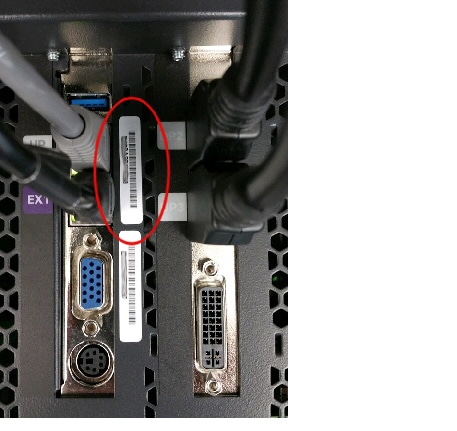
You need the codec MAC address to configure your system in Unified CM. There are two MAC addresses on the codec. Use the address that is nearest the Uplink and EX1 Ethernet connections. Figure 1 provides an example.

Tip You can also find this address on the blue screen while your system is booting up.
Figure 1 MAC Address Location on the Codec
Powering on the System and Enabling the Cisco TelePresence Administration Software GUI
To load the CTS Administration Software, complete the following steps:
Step 1 Power on the system by completing the following steps.

Note If your system is already powered on, skip the step and proceed to Step 2.
a. Remove the bottom fascia by using the following procedure:

Note While two people make this procedure easier, only one person is required.
1. While wearing gloves, grasp the fascia from the left side at the top corner and pull it outward. Let the fascia swing outward from its hinge.
2. Set the left side of the fascia on the ground, leaving it upright. Do not twist or put undue stress on the joints.
3. Move to the center of the system, pull the center of the fascia outward, and set that part on the ground.
4. Take the right end of the fascia at the upper corner, pull it outward, and set that on the ground.
Leave the center and side sections at slight angles so that it remains upright.


b. Turn on the two PDUs mounted on the lower left and lower right display frames.
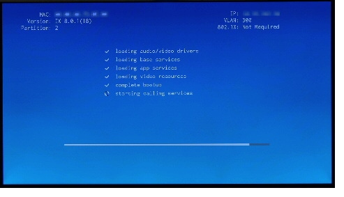
After you turn on the codecs, the IX5000 display codec becomes active. The system displays white check marks on the center display to show bootup progress. Bootup is complete when the system completes all check marks as show in Figure 2.

Tip If you have not registered the system to Unified CM, make a note of the MAC address that appears during the bootup process. The MAC address is required to register the system to Unified CM.
c. Watch the main display screen as the system is booting.
Step 2 Note the IP address that displays on the top right of the screen as shown in Figure 2. If your system has already booted, tap the top left of the Touch 10 controller, then tap Info, and note the system IP address. You use that information to sign in to the Cisco TelePresence System Administration. This IP address displays until you sign in to Cisco TelePresence System Administration or use Secure Shell (SSH) to sign in to the IX5000.

Note If the IP address that displays is 192.168.100.2, the system could not contact the DHCP server or your system does not use DHCP. If your network does not use DHCP, set a static IP address for your system as described in the “Configuring an IX5000 or IX5200 System With a Static Network Address” section.
Step 3 If you have not already done so, configure the Cisco Unified Communications Manager GUI. For detailed instructions to configure Cisco Unified Communications Manager, refer to the Configuring Cisco Unified Communications Manager for the IX System document.
Step 4 Open a browser on a computer that is connected to your network.
Step 5 In the URL field, type the IP address that you obtained in Step 2 and press Enter . The browser launches Cisco TelePresence System Administration.

Tip If you did not make a note of the IP address and it no longer appears on the display, tap the number that displays on the top left corner of the Touch 10 controller, then tap System Info.
Step 6 Log in to the system by entering the following information:
– Username: admin (case sensitive)
– Password: cisco (case sensitive)
Configuring an IX5000 or IX5200 System With a Static Network Address
Use the following procedure to assign the static address to the system.

Note If you need to set a domain name, the option to set a domain name with a static address is not available in the IX administration GUI. Instead, use the set network IP static CLI command as shown in Step 4.
Alternatively, if your system uses DHCP, you can use Mixed mode. This mode allows you to specify an IP address, but uses DHCP to assign the remainder of the network settings. To select Mixed mode, click the Mixed button in the DHCP area.
Step 1 Disconnect the Ethernet cable from the Touch 10 that sits on the table.
Step 2 Connect a DHCP-enabled PC to the Ethernet cable.
Step 3 Find the session IP address for your PC.

Tip If your PC is Windows-based, find the session IP address by clicking typing cmd in the Search box (or clicking Start > Run and typing cmd) to open a terminal window, and then typing ipconfig.
Step 4 Set the network address using either CLI commands or the IX5000 administration GUI using one of the following methods:
To set the address using CLI commands :
a. Using a Secure Shell (SSH) client, open a CLI session using the IP address 169.254.1.1 . The default username/password is admin / cisco .
b. Enter the following command to configure a static network IP address:
set network IP static ip-address ip-subnet ip-gateway [ dns-address1 ][ dns-address2 ][ domain-name ]
ip-address is the IP address of the system
ip-subnet is the IP subnet mask of the system
ip-gateway is the IP gateway of the system
– dns-address1 is the IP address of DNS server 1 (Optional)
– dns-address2 is the IP address of DNS server 2 (Optional)
– domain-name is the domain name for the network (Optional)
To set the address using the IX5000 administration GUI:
a. Using a supported web browser, log in to the Cisco TelePresence system GUI by entering the IP address 169.254.1.1 .
b. Enter the username and password when you are prompted to do so. By default, the username is admin and the password is cisco .
d. In the DHCP area, click Static .
e. Enter a static IP address, subnet mask, IP gateway, DNS server(s), and the network domain name.
Your system saves the changes and restarts.
The following example gives the Cisco TelePresence system an IP address of 10.0.0.2, a subnet of 255.255.255.0, a gateway of 10.0.0.1, a DNS server of 172.16.1.5, and a domain name of Cisco.com:
Requirements for Auxiliary Displays
- Qualified Cisco Auxiliary Displays
- Reboot Required After First-Time Setup For Systems with Auxiliary Displays
Qualified Cisco Auxiliary Displays
The following displays are qualified for use with Cisco TelePresence System running IX software:
The release notes previously reported that the 42-inch display, part number CTS-MON-42-WW is a qualified Cisco display. This part number is not a qualified Cisco display for the IX system.

Note HDMI-to-HDMI cables are not supported for display connections to the IX codec. You must use the HDMI-to-DVI connector for the displays (DVI on the display side). Some versions of the 55-inch display do not include a DVI input; use the included HDMI-to-DVI adapter to connect cables to the HDMI input on the display.
Before use, turn off all on-screen display (OSD) capability for the displays. This prevents the display from showing messages after you stop sharing a presentation. To turn off OSD, complete the following steps using the remote control that comes with the system, or use the joystick control on the back of the display:
Step 2 Press MENU on the remote, or press the center of the joystick and move the joystick to select the menu option (the choice on the left), to bring up the menu for the display.
Step 3 Using the up and down arrows, navigate to System in the menu panel.
Step 4 Press Enter if using a remote, or press the center of the joystick if using the joystick on the display, to select the System choice.
Step 5 Using the up and down arrows, navigate to General and press either Enter on the remote, or the center of the joystick on the display.
Step 6 This choice does not appear initially. Scroll down to see it.
Step 7 Navigate to OSD Display and press Enter or the center of the joystick.
Step 8 Set all three OSD choices (Source OSD, No Signal OSD, and MDC OSD) to Off (the default is On ) to disable OSD messages.
Step 9 Press EXIT on the remote, or move the joystick to the previous menu choices, until the menu no longer displays.
Reboot Required After First-Time Setup For Systems with Auxiliary Displays
If your IX system uses auxiliary displays, you must reboot the system after you complete first-time setup for the displays to be detected. After reboot, you can rerun First-Time Setup just to verify the auxiliary display configuration. After the display setup, you can exit First-Time Setup without going through the entire process again.
If you add an extra auxiliary display, you must run First-Time Setup again. If you unplug or plug a display cable, or power cycle any auxiliary display, you must reboot the system for the display to be detected.
Requirements for Whiteboards and Whiteboard Microphones
The IX system supports whiteboard projection. In addition, it supports a microphone to be placed in front of the whiteboard, so that your voice can be heard by conference participants while you use the whiteboard.
The following sections provide you with the requirements for whiteboard and whiteboard microphone placement.
Rules for Whiteboards
The whiteboard must have an aspect ratio of 16:9.

Tip A 3x5-foot whiteboard has a ratio of 15:9, which closely approximates the correct ratio.
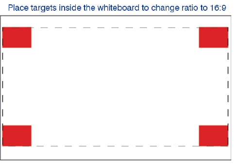
If your whiteboard is not at this ratio, you can adjust the red targets inside the perimeter of the whiteboard until the ratio is correct.
Figure 3 Framing the Whiteboard for Correct Ratio
- There are no minimum or maximum dimensions, but the whiteboard must fit entirely into the field of view of one of the three cameras. The projected area can overlap between two cameras, but it must fit entirely into one camera’s view.
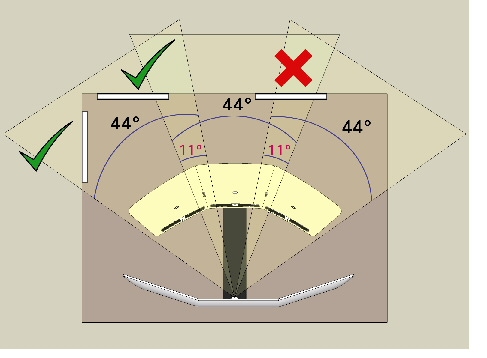
– If you want to place the whiteboard on the wall prior to the system being installed, you can calculate the angle of view for each camera and place the whiteboard accordingly. Each camera has a 44-degree angle of view (plus or minus 2 degrees). The cameras overlap 11 degrees (plus or minus 2 degrees). These angles are shown in Figure 4.
– It is more difficult to plan for the height of a whiteboard, because of meeting participants or physical obstructions blocking the view. A whiteboard can be placed below the height of the table, as long as it is within the field of view of the camera.
- The whiteboard can be placed on the back wall, or the side wall. The software de-warps the whiteboard and displays it correctly, regardless of placement.
Figure 4 illustrates correct and incorrect whiteboard placement. The first two whiteboards fit into the viewing area of the right camera. One is placed on the side wall, and one is placed on the rear wall. Either placement is acceptable.
The third whiteboard overlaps the area of view for the center and left camera, which is acceptable, but does not fit into either camera’s full area of view, which is unacceptable.

Note Figure 4 shows two whiteboards, but only one whiteboard per system can be set up and used with the whiteboard camera.
- Good lighting improves the whiteboard image; poorly lit whiteboard areas can look grainy when shared in a conference.
Figure 4 Examples of Correct and Incorrect Whiteboard Placement
Troubleshooting Whiteboard Setup Issues
If you encounter any problems with the whiteboard setup, check the following possible causes:
- There is not enough contrast between the targets and the viewable area in the camera, due to poor lighting in the whiteboard area. Ideally, the lux level in the whiteboard area should be the same level as the rest of the room. If the whiteboard is placed in a dark corner of the room, not only can whiteboard setup fail, but the whiteboard can look dark and grainy when it is shared, even if whiteboard setup passes.
If you cannot fix the lighting, you can light the whiteboard area temporarily with an external lighting source until first-time setup passes. However, note that a poorly lit whiteboard area looks poorly lit when it is shared.
- Something in the viewable camera area (for example, red ink on the whiteboard) is causing detection issues between the whiteboard targets, which are red in color, and the whiteboard.
This problem is unlikely because to interfere with camera setup, the source of the interference would have to be both red and rectangular in shape.
Performing First-Time Setup
To set up your system for the first time, complete the following steps.
Step 1 Log in to the IX5000 administration GUI using the following syntax:
ip-address is the IP address you noted when the system was booting (see Figure 2 for an example).

Tip If you did not make a note of the IP address and it no longer appears on the display, tap the number that displays on the top left corner of the Touch 10 controller, then tap System Info.
Step 2 Click First-Time Setup from the menu on the left.
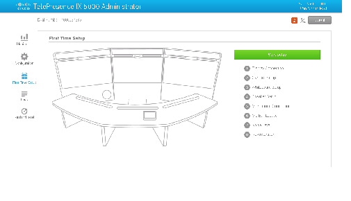
Step 4 Perform initial setup of the main and auxiliary displays (if present) by completing the following steps:
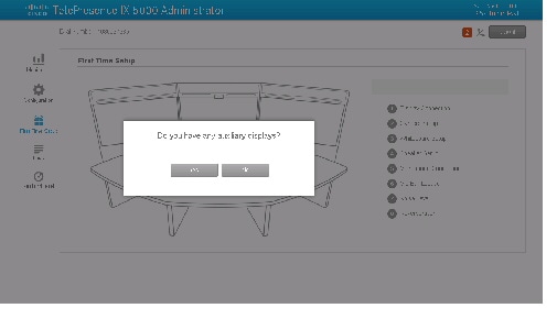
a. If you have auxiliary displays in addition to the three main displays, click Yes; if not, click No and continue to Step c.
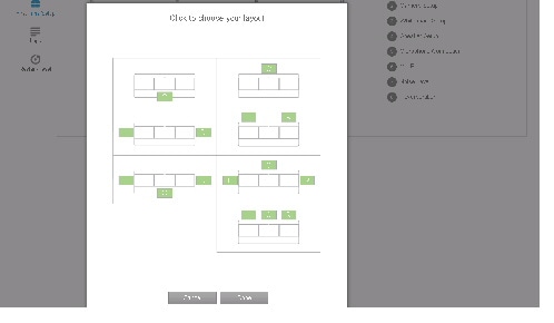
b. Click the correct auxiliary display layout, then click Done.

Tip If you clicked Yes in error and your system does not have auxiliary displays, click Cancel and continue to the next step.
c. If the graphic shows the correct position of the displays, click Continue. If not, click Exit Setup, power down your system, and check the cabling for your system.
Make sure that any auxiliary displays are correctly cabled as follows:
– If a single auxiliary display is present, connect it to the H5 port.
– If two auxiliary displays are present, connect the left display to the H4 port and the right display to the H6 port. The H5 port should remain unused.
– If three auxiliary displays are present, connect the left display to the H4 port, the center display to the H5 port, and the right display to the H6 port.
For more information, see the “Cable Routing Diagrams” section in the Cisco TelePresence IX5000 and IX5200 Installation Guide .
Hot swapping of cables is not supported. Be sure to boot or reboot your system after you make any cabling changes.

Step 5 Perform camera alignment for your system. If you have a two-table system, proceed to step 5d.
a. Place the camera targets (included with the system) so that the line on the back of the target is flush with the seams between the center and side tabletops.
b. Be sure that the rear edge of the target is flush with the rear edge of the table.
c. Be sure that the tabletop is clear, especially the rear edge, then click Continue to begin the test. Proceed to step 5e.
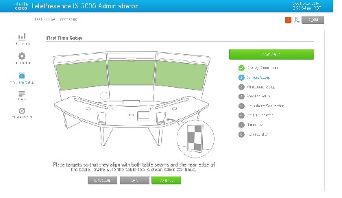
d. If you have 14- or 18-seat seating, you see the following prompt:
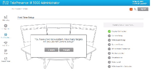
Click 2 targets or 4 targets .
– If you select 2 targets, place the camera targets on the front table in the same positions as shown in step 5c. above.
– If you select 4 targets, place the camera targets on the front and rear tables in the locations shown below.
The line on the back of the target should be flush with the seams between the center and side tabletops. Be sure that the tabletop is clear, especially the rear edge, then click Continue to begin the test.
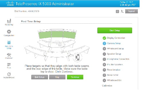
e. If the test fails, make sure that the targets are placed correctly, and that the table edges are free of any obstructions, and rerun first-time setup from the beginning.
If the IX system is installed with a Walnut table and the camera alignment continues to fail, there may be a contrast conflict between the table edge and table pattern. To complete the camera alignment in this case, perform the following steps:
– Place a black strip of semi-adhesive tape along the entire table edge as shown in the figure.

One inch of tape must be exposed along the table to develop a distinct edge for camera detection. The recommended tape is 3M Black colored plastic tape /MFG Part # MMM 19-RD.
– Perform the camera calibration again.
– Remove the tape from the table edge and clean any residue remaining from the tape.
f. When the test is complete, click Continue to validate the setup.
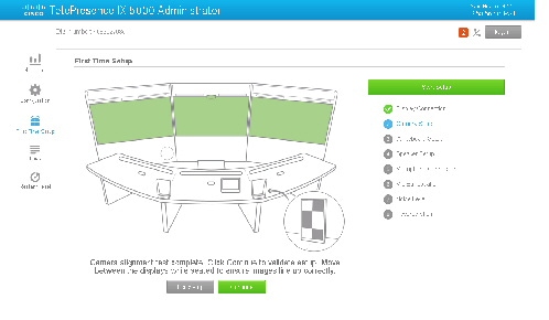
Remain seated, and move between the cameras. Make sure that objects between the displays are not shortened or elongated.

Tip Move your arms between the left and center, and center and right displays, and make sure that your arm is displayed at the correct length.
g. If you are satisfied with the camera setup, click Continue to see the stand-up view.
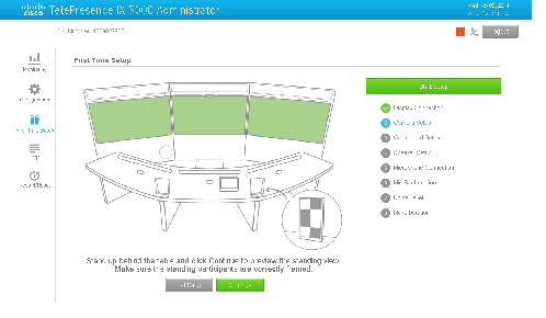
Stand up and move between the cameras. If the camera alignment did not perform correctly, click Exit Setup and rerun the first-time setup from the beginning.

Note Stand-up view was designed for a maximum participant height of 6 feet (183 cm). Taller participants might not fit fully in the screen. This condition is normal and does not invalidate the test. Move backwards to fit fully into the camera view.
h. If both the sitting and standing view are acceptable, click Continue to continue to the camera white balance calibration.
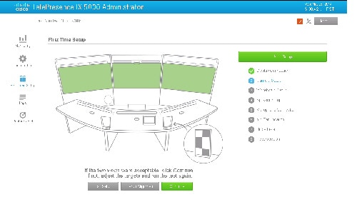
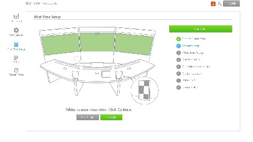
i. When white balance is complete, click Continue to continue to the whiteboard setup.
Step 6 If your system has a whiteboard, set up the whiteboard for viewing by completing the following steps.
Whiteboards must have the following characteristics:
- The whiteboard must have a width-to-height ratio of 16:9. Other width-to-height ratios cause the whiteboard to be stretched or compressed when it is reproduced.
- The whiteboard must be entirely in the viewable area of a single camera. See Figure 4 for examples.
a. Place the four red magnetic targets (included with the system) on the corners of the whiteboard target. If your whiteboard ratio is not 16:9, move the targets until the ratio is 16:9.

Tip If your whiteboard is not magnetic, place tape on the back of the targets.
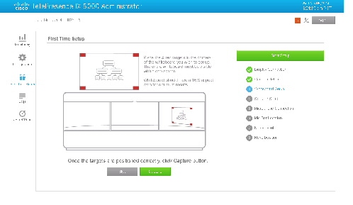

c. If the whiteboard is properly selected, and if the whiteboard is completely in the view of a single camera, click Select Whiteboard. If the image is not properly selected, move the targets and click Re-Capture.

Note If the whiteboard setup fails, increase the amount of lighting to the whiteboard until the red targets are recognized by the system. For more information about whiteboard lighting requirements, see “Troubleshooting Whiteboard Setup Issues” section.
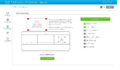
d. Click Continue to continue to the speaker setup.
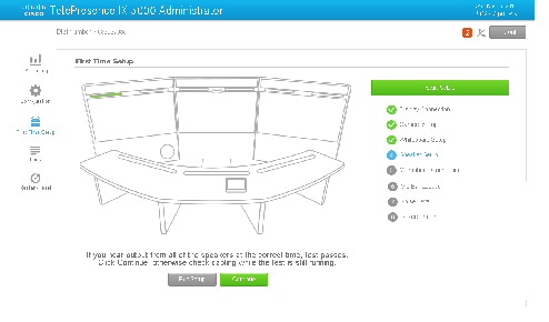
Step 7 Listen while the system plays sound from all system speakers. If you hear the sound correctly, click Continue to move to the microphone connection test. If a speaker does not play sound, click Exit Setup, power off the system, check the cabling for the speakers, power the system back up, and run first-time setup again.
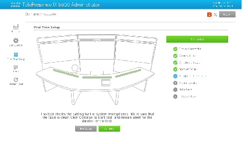
Step 8 Make sure that the table is clear, make sure that there is no noise in the room, and click Continue.
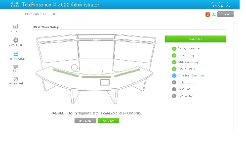
Step 9 When the test passes, click Continue. If the test finds any problems, click Exit Setup and fix the problem, then return to first-time setup.
Step 10 Continue to the microphone connector test. Sit in front of a mic bar. Speak into one side of a mic bar (there are two segments to a single mic bar), or lightly scratch one side of a mic bar with your fingernail.
Icons on the screen light up and indicate the mic bar that is being activated.
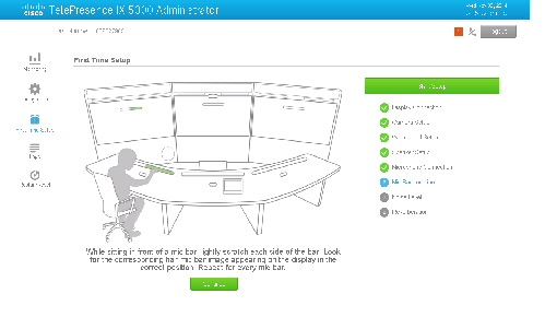
Step 11 Click Continue. Repeat this test for every mic bar segment (six in total for the first row, 12 in total for the second row). If you detect any problems, click Exit Setup and check the microphone cabling between the mic bar, TDM, and Host CPU codec.

Tip If the problem affects all mic bars, check the cabling between the TDM and the codec (the TDM is located in the first and, if applicable, second row cable management panels). If the problem is with a single mic bar, check the cabling between the mic bar and the TDM.

Note The Audio components are not hot pluggable. If you need to change working connections, you need to reboot the IX system and run the first-time setup again.
Step 12 Click Continue to continue to the reverberation rest.
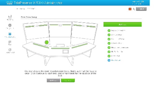
Step 13 Click Continue to run the reverberation test. This test typically takes a few minutes to complete.
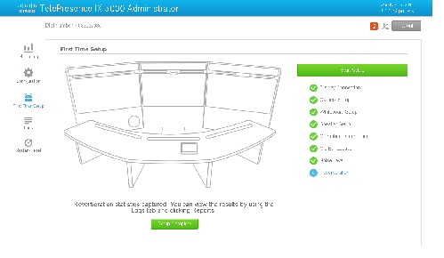
Step 14 Click Continue to move to the noise level test.
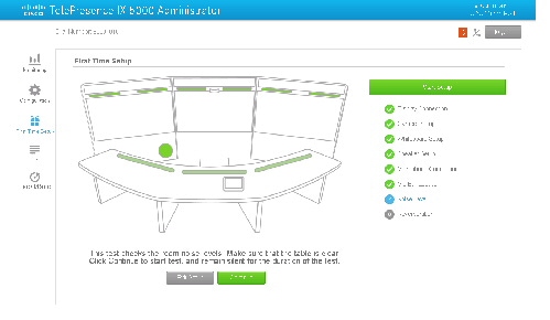
Step 15 Make sure that the room is quiet and click Continue to start the noise level test. Remain quiet during the test.

Note This test takes up to five minutes to complete.
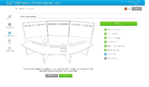
Step 16 When the noise level test completes, click Continue.

Tip After you run the noise level and reverberation tests, download and view the results by completing the steps in the “Retrieving and Reading the Results of the Noise Level and Reverberation Tests” section.
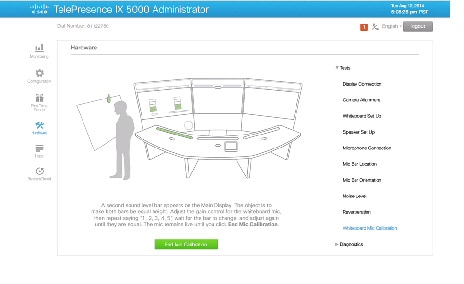
Step 17 Set up the whiteboard microphone (if present) by completing the following steps:

Note For more information about whiteboard microphones, see the “Requirements for the Whiteboard Microphone” section
a. Speak normally in front of the mic bar closest to the whiteboard.

b. Walk to the whiteboard and speak normally in front of the whiteboard.

Two sound bars appear on the display.
c. Adjust the gain dial knob on the preamp until the two sound bars are the same level.
Step 18 When the test completes, verify that all of the appropriate FTS tests show a green check mark. All nine tests should show a check mark if your system includes a whiteboard. If your system does not include a whiteboard, all tests should show a check mark, except Whiteboard Setup and Whiteboard Mic Calibration.
Step 19 If your system includes auxiliary displays, you must reboot the system for the displays to be detected. For more information, see “Reboot Required After First-Time Setup For Systems with Auxiliary Displays” section.
Requirements for the Whiteboard Microphone
The whiteboard microphone is used when a person at the whiteboard is speaking. It allows participants to be heard while they are presenting.
The whiteboard microphone must fit the following characteristics:
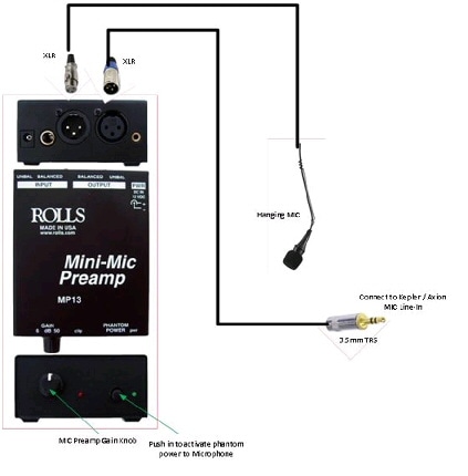
- The microphone must be omnidirectional (wireless or corded) and have a minimum frequency response of 100Hz to 10KHz (+/- 3dB).
- The microphone must include an adjustable preamp with a gain knob and power supply (maximum input voltage +3dBV).
- The output line must use a 3.5mm TRS connector to connect to the Host CPU codec.
Figure 5 illustrates a sample whiteboard microphone.
Figure 5 Whiteboard Microphone Example
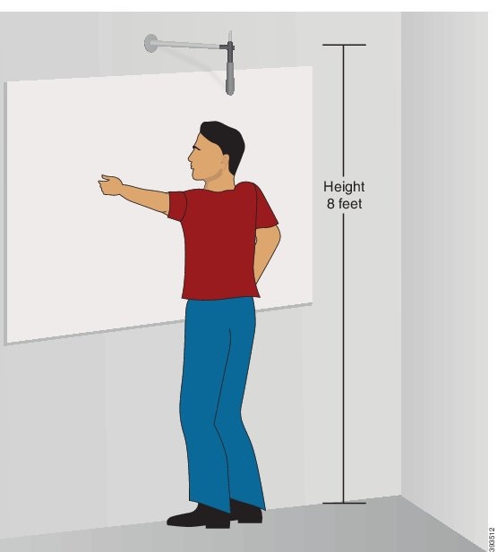
- The whiteboard microphone should be approximately 8 feet (2.44 meters) from the floor, and approximately 18 inches (46 cm) from the whiteboard.

Tip Wired or wireless microphones are permitted. A boom is not required.
Figure 6 Whiteboard Microphone Placement Example
Retrieving and Reading the Results of the Noise Level and Reverberation Tests
After you run the noise level and reverberation tests, you can retrieve the reports by navigating to Logs > Reports in the Administration GUI. You see a list of .html files whose filenames begin with Noise and RT60. Click Download to open and view the reports in an HTML browser.
Figure 7 Reports Screen and RT60 and Noise Level HTML File Example.
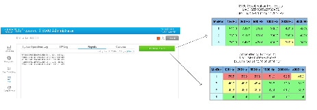
Most of the information in the HTML files is self-explanatory. More descriptions of the fields follow:
- MicBar column (for RT60 and Ambient Noise results): The numbers in MicBar area 1, 2, and 3 refer to the left, center, and right microphone bars, respectively. If you have a two-row system, 4 to 9 refer to the second row mic bars, going from left to right.
- 0.0 result (RT60 reverberation test only): If the RT60 measurement is 0.0, the result was out of range. This condition can be caused by a high level of noise in the room. Repeating the test should cause a valid result above 0.0 to appear. If, after rerunning the tests, the results are still 0.0, reverberation in the room is very high, which will adversely affect the audio quality of TelePresence calls. Remediation procedures, such as adding an acoustic panel in the room to reduce reverberation and room noise, might be required.
Cisco and the Cisco logo are trademarks or registered trademarks of Cisco and/or its affiliates in the U.S. and other countries. To view a list of Cisco trademarks, go to this URL: www.cisco.com/go/trademarks . Third-party trademarks mentioned are the property of their respective owners. The use of the word partner does not imply a partnership relationship between Cisco and any other company. (1110R)
Contact Cisco
- Open a Support Case

- (Requires a Cisco Service Contract)
 Feedback