- Preface
- Chapter 1 - Product Overview
- Chapter 2 - Preparing for Installation
- Chapter 3 - Installing the Client Adapter
- Chapter 4 - Using the Profile Manager
- Chapter 5 - Configuring the Client Adapter
- Chapter 6 - Using EAP Authentication
- Chapter 7 - Performing Diagnostics
- Chapter 8 - Using the Aironet Client Monitor (ACM)
- Chapter 9 - Routine Procedures
- Chapter 10 - Troubleshooting
- Appendix A - Technical Specifications
- Appendix B - Translated Safety Warnings
- Appendix C - Declarations of Conformity and Regulatory Information
- Appendix D - Channels, Power Levels, and Antenna Gains
- Appendix E - Configuring the Client Adapter through Windows XP
- Appendix F - Performing a Site Survey
- Glossary
- Index
Cisco Aironet 340, 350, and CB20A Wireless LAN Client Adapters Installation and Configuration Guide for Windows, OL-1394-05
Bias-Free Language
The documentation set for this product strives to use bias-free language. For the purposes of this documentation set, bias-free is defined as language that does not imply discrimination based on age, disability, gender, racial identity, ethnic identity, sexual orientation, socioeconomic status, and intersectionality. Exceptions may be present in the documentation due to language that is hardcoded in the user interfaces of the product software, language used based on RFP documentation, or language that is used by a referenced third-party product. Learn more about how Cisco is using Inclusive Language.
- Updated:
- May 4, 2007
Chapter: Chapter 7 - Performing Diagnostics
Performing Diagnostics
This chapter explains how to use ACU to perform user-level diagnostics.
The following topics are covered in this chapter:
•![]() Overview of ACU Diagnostic Tools
Overview of ACU Diagnostic Tools
•![]() Setting Parameters that Affect ACU Diagnostic Tools
Setting Parameters that Affect ACU Diagnostic Tools
•![]() Viewing the Current Status of Your Client Adapter
Viewing the Current Status of Your Client Adapter
•![]() Viewing Statistics for Your Client Adapter
Viewing Statistics for Your Client Adapter
•![]() Viewing the Link Status Meter
Viewing the Link Status Meter
Overview of ACU Diagnostic Tools
In addition to enabling you to configure your client adapter for use in various types of networks, ACU provides tools that enable you to assess the performance of the client adapter and other devices on the wireless network. ACU diagnostic tools perform the following functions:
•![]() Display your client adapter's current status and configured settings
Display your client adapter's current status and configured settings
•![]() Display statistics pertaining to your client adapter's transmission and reception of data
Display statistics pertaining to your client adapter's transmission and reception of data
•![]() Display a graphical image of your client adapter's RF link
Display a graphical image of your client adapter's RF link
•![]() Run an RF link test to assess the performance of the RF link between your client adapter and its associated access point
Run an RF link test to assess the performance of the RF link between your client adapter and its associated access point
Table 7-1 enables you to quickly locate instructions for using each of the diagnostic tools.
|
|
|
|---|---|
Status |
|
Statistics |
|
Link status meter |
|
RF link test |
Setting Parameters that Affect ACU Diagnostic Tools
Several parameters affect the operation of ACU diagnostic tools. Follow the steps below to set these parameters.
Step 1 ![]() Open ACU.
Open ACU.
Step 2 ![]() Click the Preferences icon or select Preferences from the Options drop-down menu. The Aironet Client Utility Preferences screen appears (see Figure 7-1).
Click the Preferences icon or select Preferences from the Options drop-down menu. The Aironet Client Utility Preferences screen appears (see Figure 7-1).
Figure 7-1 Aironet Client Utility Preferences Screen
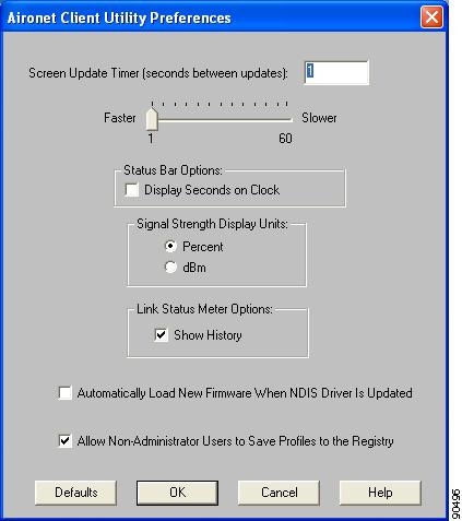
Step 3 ![]() Table 7-2 lists and describes the parameters that affect the operation of ACU diagnostic tools. Follow the instructions in the table to change any parameters.
Table 7-2 lists and describes the parameters that affect the operation of ACU diagnostic tools. Follow the instructions in the table to change any parameters.
Step 4 ![]() Click OK to save your changes.
Click OK to save your changes.
Viewing the Current Status of Your Client Adapter
ACU enables you to view the current status of your client adapter as well as many of the settings that have been configured for the adapter.
To view your client adapter's status and settings, open ACU; then click the Status icon or select Status from the Commands drop-down menu. The Status screen appears. Figure 7-2 shows the Status screen with the signal strength values displayed as percentages, and Figure 7-3 shows the bottom of the same screen with the signal strength values displayed in decibels with respect to milliwatts (dBm).

Note ![]() The name of the current profile appears in parentheses at the top of the screen.
The name of the current profile appears in parentheses at the top of the screen.
Figure 7-2 Status Screen (with Signal Strength as a Percentage)
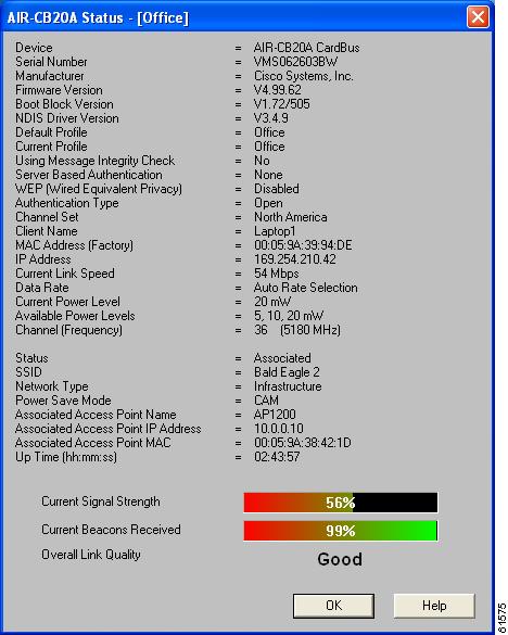
Figure 7-3 Bottom of Status Screen (with Signal Strength in dBm)
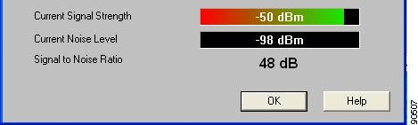
Table 7-3 interprets each element of the Status screen.
|
|
|
|
|---|---|---|
Device |
A description of your client adapter. |
|
Serial Number |
The serial number of your client adapter. Note |
|
Manufacturer |
The manufacturer of your client adapter. |
|
Firmware Version |
The version of the firmware that is currently running on your client adapter. |
|
Boot Block Version |
The version of the boot block firmware that is currently in your client adapter. The boot block firmware contains identification information for the client adapter and functions to start up the radio and pass control to the main firmware, which (unlike the boot block) can be modified and upgraded by the user. |
|
NDIS Driver Version |
The version of the NDIS device driver that is currently installed on your computer. |
|
Default Profile |
The network configuration (or profile) shown in the Use Selected Profile drop-down box on the Profile Manager screen. This is the profile that you have selected as the active profile. Note |
|
Current Profile |
The network configuration (or profile) your client adapter is currently using. Note Note |
|
Using Short Radio Headers |
Indicates whether your client adapter is actually using short radio headers. Value: Yes or No Note Note |
|
Using Message Integrity Check |
Indicates whether your client adapter is using message integrity check (MIC) to protect packets sent to and received from the access point. MIC prevents bit-flip attacks on encrypted packets. During a bit-flip attack, an intruder intercepts an encrypted message, alters it slightly, and retransmits it, and the receiver accepts the retransmitted message as legitimate. Note Value: Yes or No |
|
Server Based Authentication |
Indicates the configuration of the access point to which your client adapter is associated. Value: None, WEP Key In Use, Cell Is Secure, or LEAP Authenticated |
|
|
|
|
|
None |
The access point is configured for No Encryption. |
|
WEP Key In Use |
The access point is configured for Optional encryption. |
|
Cell Is Secure |
The access point is configured for Full Encryption. Note |
|
LEAP Authenticated |
The client is using LEAP and is authenticated to an access point that has WEP and Network-EAP enabled. |
|
WEP (Wired Equivalent Privacy) |
Your client adapter's current WEP status. Value: Enabled, Not Enabled, or Need Firmware Upgrade Note |
|
Authentication Type |
Indicates whether the client adapter must share the same WEP keys as the access point in order to communicate or can communicate with the access point regardless of its WEP settings. Value: Open or Shared Key Note |
|
Antenna Selection |
The antenna mode that your client adapter is currently using. Value: Diversity, Primary Only, Secondary Only Note Note |
|
Channel Set |
The regulatory domain for which your client adapter is currently configured, such as Americas. (For the Japan channel set, the Call ID is also displayed.) This value is not user selectable. Note |
|
Client Name |
The name your client adapter uses when it associates to an access point. Note |
|
MAC Address |
The MAC address assigned to your client adapter at the factory. |
|
IP Address |
The IP address of your client adapter. |
|
Current Link Speed |
The rate at which your client adapter is currently transmitting data packets. Value: 1, 2, 5.5, or 11 Mbps (2.4-GHz client adapters); |
|
Data Rate |
The rate at which your client adapter has been configured to transmit or receive data packets. Value: 1 Mbps, 2 Mbps, 5.5 Mbps, 11 Mbps, or Auto Rate Selection (2.4-GHz client adapters); Note |
|
Current Power Level |
The power level at which your client adapter is currently transmitting. The maximum level is dependent upon the radio installed in your client adapter and your country's regulatory agency. Value: 1, 5, 15, or 30 mW (340 series client adapters); Note |
|
Available Power Levels |
The power levels at which your client adapter is capable of transmitting. The maximum level is dependent upon the radio installed in your client adapter and your country's regulatory agency. Value: 1, 5, 15, or 30 mW (340 series client adapters); Note |
|
Channel (Frequency) |
The frequency that your client adapter is currently using as the channel for communications. Value: Dependent on client adapter radio and regulatory domain Note |
|
Status |
The operational mode of your client adapter. Value: Error, Not Associated, Associated, Authenticating, Authenticated, Authentication Failed, or Ad Hoc Mode |
|
SSID |
The name of the network to which your client adapter is currently associated. Note |
|
Network Type |
The type of network in which your client adapter is being used. Value: Infrastructure or Ad Hoc Note |
|
Power Save Mode |
The client adapter's current power consumption setting. Value: CAM, Max PSP, or Fast PSP Note |
|
Associated Access Point Name |
The name of the access point to which your client adapter is associated. It is shown only if the client adapter is in infrastructure mode, the access point was configured with a name, and Aironet Extensions are enabled (on access points running Cisco IOS release 12.2(4)JA or greater). |
|
Associated Access Point IP Address |
The IP address of the access point to which your client adapter is associated. It is shown only if the client adapter is in infrastructure mode, the access point was configured with an IP address, and Aironet Extensions are enabled (on access points running Cisco IOS release 12.2(4)JA or greater). Note |
|
Associated Access Point MAC Address |
The MAC address of the access point to which your client adapter is associated. It is shown only if the client adapter is in infrastructure mode. Note |
|
Beacon Period |
Specifies the duration between beacon packets, which are used to help clients find each other in ad hoc mode. Range: Approximately 20 to 999 milliseconds (ms) Note |
|
Up Time (hh:mm:ss) |
The amount of time (in hours:minutes:seconds) that the client adapter has been receiving power. If the adapter has been running for more than 24 hours, the time is displayed in days, hours:minutes:seconds. |
|
Current Signal Strength |
The signal strength for all received packets. The higher the value and the more green the bar graph is, the stronger the signal. Range: 0 to 100% or -95 to -45 dBm |
|
Current Signal Quality (2.4-GHz client adapters) |
The signal quality for all received packets. The higher the value and the more green the bar graph is, the clearer the signal. Range: 0 to 100% Note |
|
Current Noise Level (2.4-GHz client adapters) |
The level of background radio frequency energy in the 2.4-GHz band. The lower the value and the more green the bar graph is, the less background noise present. Range: -100 to -45 dBm Note |
|
Current Beacons Received (5-GHz client adapters) |
The percentage of beacon packets received versus those expected to be received. The higher the value and the more green the bar graph is, the clearer the signal. Example: The access point sends out 10 beacons per second, so you Range: 0 to 100% Note |
|
Overall Link Quality |
The client adapter's ability to communicate with the access point, which is determined by the combined result of the adapter's signal strength and signal quality. Value: Not Associated, Poor, Fair, Good, Excellent Note |
|
Signal to Noise Ratio (2.4-GHz client adapters) |
The difference between the signal strength and the current noise level. The higher the value, the better the client adapter's ability to communicate with the access point. Range: 0 to 90 dB Note |
|
Viewing Statistics for Your Client Adapter
ACU enables you to view statistics that indicate how data is being received and transmitted by your client adapter.
To view your client adapter's statistics, open ACU; then click the Statistics icon or select Statistics from the Commands drop-down menu. The Statistics screen appears (see Figure 7-4).
Note ![]() The name of the current profile appears in parentheses at the top of the screen.
The name of the current profile appears in parentheses at the top of the screen.
Note ![]() The receive and transmit statistics are host statistics. That is, they show packets and errors received or sent by the Windows device. Link status tests from the access point or site survey tool are performed at the firmware level; therefore, they have no effect on the statistics shown in the Statistics screen.
The receive and transmit statistics are host statistics. That is, they show packets and errors received or sent by the Windows device. Link status tests from the access point or site survey tool are performed at the firmware level; therefore, they have no effect on the statistics shown in the Statistics screen.
Figure 7-4 Statistics Screen
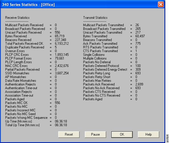
The statistics are calculated as soon as your client adapter is started or the Reset button is selected and are continually updated at the rate specified by the Screen Update Timer. Instructions for changing the Screen Update Timer setting are provided in Table 7-2.
Table 7-4 describes each statistic that is displayed for your client adapter.
|
|
|
|---|---|
|
|
|
Multicast Packets Received |
The number of multicast packets that were received successfully. |
Broadcast Packets Received |
The number of broadcast packets that were received successfully. |
Unicast Packets Received |
The number of unicast packets that were received successfully. |
Bytes Received |
The number of bytes of data that were received successfully. |
Beacons Received |
The number of beacon packets that were received successfully. |
Total Packets Received OK |
The number of all packets that were received successfully. |
Duplicate Packets Received |
The number of duplicate packets that were received successfully. |
Overrun Errors |
The number of packets received when no receive buffers were available. These errors usually occur when the host does not read the received packets from the client adapter fast enough. |
PLCP CRC Errors |
The number of times the client adapter started to receive an 802.11 physical layer convergence protocol (PLCP) header but the rest of the packet was ignored due to a cyclic redundancy check (CRC) error in the header. Note |
PLCP Format Errors |
The number of times an 802.11 PLCP header was received with a valid CRC but the rest of the packet was ignored due to an unknown value in the header. |
PLCP Length Errors |
The number of times an 802.11 PLCP header was received but the rest of the packet was ignored due to an illegal header length. |
MAC CRC Errors |
The number of packets that had a valid 802.11 PLCP header but contained a CRC error in the data portion of the packet. Note |
Partial Packets Received |
The number of fragments that were discarded because the entire packet was not received successfully. |
SSID Mismatches |
The number of times the client adapter tried to associate to an access point but was unable to because the adapter's SSID was not the same as the access point's. |
AP Mismatches |
The number of times the client adapter tried to associate to an access point but was unable to because the access point was not the adapter's specified access point. Note |
Data Rate Mismatches |
The number of times the client adapter tried to associate to an access point but was unable to because the adapter's data rate was not supported by the access point. Note |
Authentication Rejects |
The number of times the client adapter tried to authenticate to an access point but was rejected. |
Authentication Time-out |
The number of times the client adapter tried to authenticate to an access point but was unable to because the access point did not respond fast enough (timed out). |
Association Rejects |
The number of times the client adapter tried to associate to an access point but was rejected. |
Association Time-out |
The number of times the client adapter tried to associate to an access point but was unable to because the access point did not respond fast enough (timed out). |
Packets Aged |
The number of packets received successfully but discarded by the client adapter because either all fragments were not received within 10 seconds or the host did not read the packet from the adapter within 10 seconds. |
Packets MIC OK |
The number of packets that were received successfully with a valid message integrity check (MIC). Note |
Packets No MIC |
The number of packets that were discarded due to no MIC being found. Note |
Packets Incorrect MIC |
The number of packets that were discarded due to an incorrect MIC value. Note |
Packets No MIC Seed |
The number of packets that were discarded due to no MIC seed being received. Note |
Packets Wrong MIC Sequence |
The number of packets that were discarded due to the MIC sequence number being wrong. Note |
Up Time (hh:mm:ss) |
The amount of time (in hours:minutes:seconds) since the Reset button was selected. If the client adapter has been running for more than 24 hours, the time is displayed in days, hours:minutes:seconds. |
Total Up Time (hh:mm:ss) |
The amount of time (in hours:minutes:seconds) that the client adapter has been receiving power. The total up time continues to increment even if the Reset button is selected. If the adapter has been running for more than 24 hours, the time is displayed in days, hours:minutes:seconds. |
|
|
|
Multicast Packets Transmitted |
The number of multicast packets that were transmitted successfully. |
Broadcast Packets Transmitted |
The number of broadcast packets that were transmitted successfully. |
Unicast Packets Transmitted |
The number of unicast packets that were transmitted successfully. |
Bytes Transmitted |
The number of bytes of data that were transmitted successfully. |
Beacons Transmitted |
The number of beacon packets that were transmitted successfully (in ad hoc mode only). |
Ack Packets Transmitted |
The number of acknowledgment (Ack) packets that were transmitted in response to successfully received unicast packets. |
RTS Packets Transmitted |
The number of request-to-send (RTS) packets that were transmitted successfully. |
CTS Packets Transmitted |
The number of clear-to-send (CTS) packets that were transmitted in response to a successfully received RTS packet. |
Single Collisions |
The number of packets that had to be retransmitted once due to a collision. |
Multiple Collisions |
The number of packets that had to be retransmitted more than once due to additional collisions. |
Packets No Deferral |
The number of packets that were able to be transmitted immediately without being delayed due to energy detect or protocol deferral. |
Packets Deferred Protocol |
The number of packets that were delayed due to 802.11 protocol reasons (such as not enough time left to send the packet). |
Packets Deferred Energy Detect |
The number of packets that were delayed because RF energy was already detected. This condition is usually caused by another radio transmitting a packet or by some other RF source jamming the signal (such as a microwave oven). |
Packets Retry Long |
The number of normal data packets that were retransmitted. |
Packets Retry Short |
The number of request-to-send (RTS) packets that were retransmitted. |
Packets Max Retries |
The number of packets that failed to be transmitted successfully after exhausting the maximum number of retries. |
Packets Ack Received |
The number of transmitted packets that had their corresponding acknowledgment (Ack) packet received successfully. |
Packets No Ack Received |
The number of transmitted packets that did not have their corresponding Ack packet received successfully. |
Packets CTS Received |
The number of clear-to-send (CTS) packets that were received in response to an RTS packet. |
Packets No CTS Received |
The number of packets for which no CTS packet was received in response to an RTS packet. |
Packets Aged |
The number of packets that were discarded by the client adapter because they were not transmitted successfully within 5 seconds. |
Viewing the Link Status Meter
ACU's link status meter can be used to assess the performance of your client adapter's RF link. If this tool is used to assess the RF link at various locations, you can avoid areas where performance is weak and eliminate the risk of losing the connection between your client adapter and an access point.
To open the link status meter, open ACU; then click the Link Status Meter icon or select Link Status Meter from the Commands drop-down menu. The Link Status Meter screen appears (see Figure 7-5).
Note ![]() The name of the current profile appears in parentheses at the top of the screen.
The name of the current profile appears in parentheses at the top of the screen.
Figure 7-5 Link Status Meter Screen
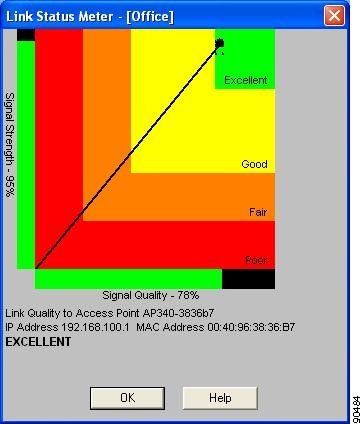
The Link Status Meter screen provides a graphical display of the following:
•![]() Signal strength—The strength of the client adapter's radio signal at the time packets are being received. It is displayed as a percentage along the vertical axis.
Signal strength—The strength of the client adapter's radio signal at the time packets are being received. It is displayed as a percentage along the vertical axis.
•![]() Signal quality—The quality of the client adapter's radio signal at the time packets are being received. It is displayed as a percentage along the horizontal axis.
Signal quality—The quality of the client adapter's radio signal at the time packets are being received. It is displayed as a percentage along the horizontal axis.
The combined result of the signal strength and signal quality is represented by a diagonal line (see Figure 7-5). Where the line falls on the graphical display determines whether the RF link between your client adapter and its associated access point is poor, fair, good, or excellent. The name, IP address, and MAC address of the access point that is associated to your client adapter are indicated at the bottom of the display.
Note ![]() The access point name and IP address are shown only if the client adapter is in infrastructure mode, the access point was configured with a name and an IP address, and Aironet Extensions are enabled (on access points running Cisco IOS release 12.2(4)JA or greater).
The access point name and IP address are shown only if the client adapter is in infrastructure mode, the access point was configured with a name and an IP address, and Aironet Extensions are enabled (on access points running Cisco IOS release 12.2(4)JA or greater).
Note ![]() The access point MAC address is shown only if the client adapter is in infrastructure mode. This field displays the MAC address of the access point's Ethernet port (for access points that do not run Cisco IOS) or the MAC address of the access point's radio (for access points that run Cisco IOS). The MAC address of the Ethernet port on access points that run Cisco IOS is printed on a label on the back of the device.
The access point MAC address is shown only if the client adapter is in infrastructure mode. This field displays the MAC address of the access point's Ethernet port (for access points that do not run Cisco IOS) or the MAC address of the access point's radio (for access points that run Cisco IOS). The MAC address of the Ethernet port on access points that run Cisco IOS is printed on a label on the back of the device.
Note ![]() ACU's Status screen also shows signal strength and signal quality. However on the Status screen, these data are represented by histograms.
ACU's Status screen also shows signal strength and signal quality. However on the Status screen, these data are represented by histograms.
If you want to see a recent history of the RF performance between your client adapter and its associated access point, check the Show History check box on the Aironet Client Utility Preferences screen. Black dots on the graphical display show the performance of the last 50 signals.
Running an RF Link Test
ACU's link test tool sends out pings to assess the performance of the RF link. The test is designed to be performed multiple times at various locations throughout your area and is run at the data rate set on ACU's RF Network Properties screen (see the Data Rate parameter in Table 5-3). The results of the link test can be used to determine RF network coverage and ultimately the required number and placement of access points in your network. The test also helps you to avoid areas where performance is weak, thereby eliminating the risk of losing the connection between your client adapter and its associated access point.
Because the link test operates above the RF level, it does more than test the RF link between two network devices. It also checks the status of wired sections of the network and verifies that TCP/IP and the proper drivers have been loaded.
The following prerequisites are required before you can run an RF link test:
•![]() The TCP/IP protocol must be installed on your system.
The TCP/IP protocol must be installed on your system.
Note ![]() See the Help section of your Windows operating system for information on installing and setting up TCP/IP.
See the Help section of your Windows operating system for information on installing and setting up TCP/IP.
•![]() An IP address must be configured for the access point (or other computer in ad hoc mode).
An IP address must be configured for the access point (or other computer in ad hoc mode).
Follow the steps below to run an RF link test.
Step 1 ![]() Open ACU; then click the Link Test icon or select Linktest from the Commands drop-down menu. The Linktest screen appears (see Figure 7-6).
Open ACU; then click the Link Test icon or select Linktest from the Commands drop-down menu. The Linktest screen appears (see Figure 7-6).
Note ![]() The name of the current profile appears in parentheses at the top of the screen.
The name of the current profile appears in parentheses at the top of the screen.
Figure 7-6 Linktest Screen
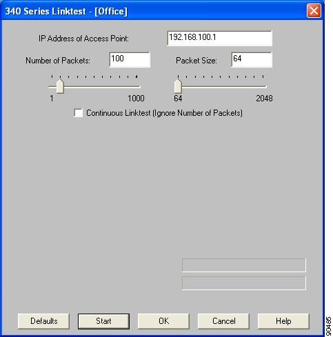
Step 2 ![]() In the IP Address of Access Point field, enter the IP address of the access point or other wireless device with which you want to test the RF link.
In the IP Address of Access Point field, enter the IP address of the access point or other wireless device with which you want to test the RF link.
Step 3 ![]() You can set the link test to run until it has attempted to send a specific number of packets or to run until you stop it. Follow one of the steps below to determine how long the link test will run:
You can set the link test to run until it has attempted to send a specific number of packets or to run until you stop it. Follow one of the steps below to determine how long the link test will run:
•![]() Select the number of packets that the link test should attempt to send. You can type a number in the Number of Packets field or use the slider to select this value. (The Number of Packets parameter is ignored if the Continuous Linktest check box is checked.)
Select the number of packets that the link test should attempt to send. You can type a number in the Number of Packets field or use the slider to select this value. (The Number of Packets parameter is ignored if the Continuous Linktest check box is checked.)
Range: 1 to 1000
Default: 4
•![]() Check the Continuous Linktest check box to allow the link test to run continuously.
Check the Continuous Linktest check box to allow the link test to run continuously.
Default: Unchecked
Step 4 ![]() Select the size of the data packet that is to be sent to the access point. You can type a number in the Packet Size field or use the slider to select this value.
Select the size of the data packet that is to be sent to the access point. You can type a number in the Packet Size field or use the slider to select this value.
Range: 64 to 2048
Default: 100
Note ![]() The Windows TCP/IP stack fragments (splits up) packets that are greater than 512 bytes. Therefore, the number of transmitted packets does not match the number of received packets (even if none are lost) if the packet size is greater than 512 bytes.
The Windows TCP/IP stack fragments (splits up) packets that are greater than 512 bytes. Therefore, the number of transmitted packets does not match the number of received packets (even if none are lost) if the packet size is greater than 512 bytes.
Step 5 ![]() Click the Start button to run the link test. While the test is running, statistics are displayed and updated periodically.
Click the Start button to run the link test. While the test is running, statistics are displayed and updated periodically.
Figure 7-7 shows the Linktest screen with the signal strength values displayed as percentages, and Figure 7-8 shows the bottom of the same screen with the signal strength values displayed in dBm.
Figure 7-7 Linktest Screen (with Test Running and Signal Strength as a Percentage)
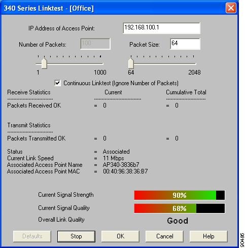
Figure 7-8 Bottom of Linktest Screen (with Test Running and Signal Strength in dBm)
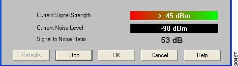
Table 7-5 interprets the statistics that are displayed on the Linktest screen while the link test is running.
|
|
|
|---|---|
Packets Received OK |
The number of packets of the specified size that have been received successfully. |
Packets Transmitted OK |
The number of packets of the specified size that have been transmitted successfully. |
Status |
The operational mode of your client adapter. Value: Error, Configured, Associated, Not Associated, or |
Current Link Speed |
The rate at which your client adapter is currently transmitting data packets. Value: 1, 2, 5.5, or 11 Mbps (2.4-GHz client adapters); |
Associated Access Point Name |
The name of the access point to which your client adapter is associated. It is shown only if the client adapter is in infrastructure mode, the access point was configured with a name, and Aironet Extensions are enabled (on access points running Cisco IOS release 12.2(4)JA or greater). |
Associated Access Point MAC Address |
The MAC address of the access point to which your client adapter is associated. It is shown only if the client adapter is in infrastructure mode. Note |
Current Signal Strength |
The signal strength for all received packets. The higher the value and the more green the bar graph is, the stronger the signal. Range: 0 to 100% or -95 to -45 dBm |
Current Signal Quality |
The signal quality for all received packets. The higher the value and the more green the bar graph is, the clearer the signal. Range: 0 to 100% Note |
Current Noise Level |
The level of background radio frequency energy in the 2.4-GHz band. The lower the value and the more green the bar graph is, the less background noise present. Range: -100 to -45 dBm Note |
Current Beacons Received (5-GHz client adapters) |
The percentage of beacon packets received versus those expected to be received. The higher the value and the more green the bar graph is, the clearer the signal. Example: The access point sends out 10 beacons per second, so Range: 0 to 100% Note |
Overall Link Quality |
The client adapter's ability to communicate with the access point, which is determined by the combined result of the adapter's signal strength and signal quality. Value: Not Associated, Poor, Fair, Good, Excellent Note |
Signal to Noise Ratio |
The difference between the signal strength and the current noise level. The higher the value, the better the client adapter's ability to communicate with the access point. Range: 0 to 90 dB Note |
Step 6 ![]() If you did not set the link test to run continuously, the test ends after the specified number of packets is sent, and the Stop button changes back to the Start button. To stop the link test at any time, click Stop, OK, or Cancel.
If you did not set the link test to run continuously, the test ends after the specified number of packets is sent, and the Stop button changes back to the Start button. To stop the link test at any time, click Stop, OK, or Cancel.
 Feedback