Feedback Feedback
|
Table Of Contents
Configuring IP Multicast over Unidirectional Links
How to Route IP Multicast over Unidirectional Links
Configuration Examples for UDLR
Integrated UDLR Tunnel, IGMP UDLR, and IGMP Proxy: Example
Feature Information for Configuring IP Multicast over Unidirectional Links
Configuring IP Multicast over Unidirectional Links
IP multicast requires bidirectional communication, yet some networks include broadcast satellite links, which are unidirectional. Unidirectional link routing (UDLR) provides three mechanisms for a router to emulate a bidirectional link to enable the routing of unicast and multicast packets over a physical unidirectional interface, such as a broadcast satellite link. The mechanisms are a UDLR tunnel, Internet Group Management Protocol (IGMP) UDLR, and IGMP proxy. This document describes a UDLR tunnel and IGMP UDLR. IGMP proxy is described in the "Customizing IGMP" module. The three mechanisms may be used independently or in combination.
Module History
This module was first published on May 2, 2005, and last updated on May 2, 2005.
Finding Feature Information in This Document
Use the "Feature Information for Configuring IP Multicast over Unidirectional Links" section to find information about feature support and configuration.
Contents
•
How to Route IP Multicast over Unidirectional Links
•
•
Prerequisites for UDLR
This module assumes you have met the following prerequisites:
•
•
Information About UDLR
Before you configure unidirectional link routing, you should understand the following concepts:
UDLR Overview
Both unicast and multicast routing protocols forward data on interfaces from which they have received routing control information. This model requires a bidirectional link. However, some network links are unidirectional. For networks that are unidirectional (such as broadcast satellite links), a method of communication that allows for control information to operate in a unidirectional environment is necessary. (Note that IGMP is not a routing protocol.)
Specifically, in unicast routing, when a router receives an update message on an interface for a prefix, it forwards data for destinations that match that prefix out that same interface. This is the case in distance vector routing protocols. Similarly, in multicast routing, when a router receives a Join message for a multicast group on an interface, it forwards copies of data destined for that group out that same interface. Based on these principles, unicast and multicast routing protocols cannot be supported over UDLs without the use of UDLR. UDLR is designed to enable the operation of routing protocols over UDLs without changing the routing protocols themselves.
UDLR enables a router to emulate the behavior of a bidirectional link for IP operations over UDLs. UDLR has three complementary mechanisms for bidirectional link emulation, which are described in the following sections:
•
•
•
You can use each mechanism independently or in conjunction with the others. IGMP proxy is described in the "Customizing IGMP" module.
UDLR Tunnel
The UDLR tunnel mechanism enables IP and its associated unicast and multicast routing protocols to treat the unidirectional link (UDL) as being logically bidirectional. A packet that is destined on a receive-only interface is picked up by the UDLR tunnel mechanism and sent to an upstream router using a generic routing encapsulation (GRE) tunnel. The control traffic flows in the opposite direction of the user data flow. When the upstream router receives this packet, the UDLR tunnel mechanism makes it appear that the packet was received on a send-only interface on the UDL.
The purpose of the unidirectional GRE tunnel is to move control packets from a downstream node to an upstream node. The one-way tunnel is mapped to a one-way interface (that goes in the opposite direction). Mapping is performed at the link layer, so the one-way interface appears bidirectional. When the upstream node receives packets over the tunnel, it must make the upper-layer protocols act as if the packets were received on the send-capable UDL.
A UDLR tunnel supports the following functionality:
•
•
•
Note
IGMP UDLR
In addition to a UDLR tunnel, another mechanism that enables support of multicast routing protocols over UDLs is using IP multicast routing with IGMP, which accommodates UDLR. This mechanism scales well for many broadcast satellite links.
With IGMP UDLR, an upstream router sends periodic queries for members on the UDL. The queries include a unicast address of the router that is not the unicast address of the unidirectional interface. The downstream routers forward IGMP reports received from directly connected members (on interfaces configured to helper forward IGMP reports) to the upstream router. The upstream router adds the unidirectional interface to the (*, G) outgoing interface list, thereby enabling multicast packets to be forwarded down the UDL.
In a large enterprise network, it is not possible to be able to receive IP multicast traffic via satellite and forward the traffic throughout the network. This limitation exists because receiving hosts must be directly connected to the downstream router. However, you can use the IGMP proxy mechanism to overcome this limitation. Refer to the "Customizing IGMP" module for more information on this mechanism.
How to Route IP Multicast over Unidirectional Links
This section includes the following procedures. You can do either or both in your network. If you want to configure IGMP Proxy, refer to the "Customizing IGMP" module.
•
•
Configuring a UDLR Tunnel
To configure a UDLR tunnel, perform the task in this section. The tunnel mode defaults to GRE. You need not assign an IP address to the tunnel (you need not use the ip address or ip unnumbered commands). You must configure the tunnel endpoint addresses.
You must configure both the upstream and downstream routers to meet the following conditions:
•
•
Prerequisite
Before configuring UDLR tunnel, ensure that all routers on the UDL have the same subnet address. If all routers on the UDL cannot have the same subnet address, the upstream router must be configured with secondary addresses to match all the subnets that the downstream routers are attached to.
SUMMARY STEPS
1.
2.
3.
4.
5.
6.
7.
8.
9.
10.
11.
12.
13.
14.
15.
16.
DETAILED STEPS
Configuring IGMP UDLR
To configure an IGMP UDL, you must configure both the upstream and downstream routers. You need not specify whether the direction is sending or receiving; IGMP learns the direction by the nature of the physical connection.
When the downstream router receives an IGMP report from a host, the router sends the report to the IGMP querier associated with the UDL interface identified in the ip igmp helper-address command.
Prerequisites
Before configuring IGMP UDLR, ensure that the following conditions exist:
•
•
SUMMARY STEPS
1.
2.
3.
4.
5.
6.
7.
8.
9.
10.
11.
12.
13.
DETAILED STEPS
Configuration Examples for UDLR
This section includes the following examples:
•
UDLR Tunnel: Example
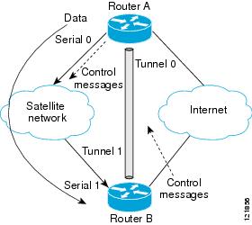
The following example shows how to configure a UDLR tunnel. In the example, Router A (the upstream router) is configured with Open Shortest Path First (OSPF) and PIM. Serial interface 0 has send-only capability. Therefore, the UDLR tunnel is configured as receive only, and points to serial 0.
Router B (the downstream router) is configured with OSPF and PIM. Serial interface 1 has receive-only capability. Therefore, the UDLR tunnel is configured as send-only, and points to serial 1. The forwarding of ARP and NHRP is enabled. Figure 1 illustrates the example.
Figure 1 UDLR Tunnel Example
Router A Configuration
ip multicast-routing!! Serial0 has send-only capability!interface serial 0encapsulation hdlcip address 10.1.0.1 255.255.0.0ip pim sparse-dense-mode!! Configure tunnel as receive-only UDLR tunnel.!interface tunnel 0tunnel source 11.0.0.1tunnel destination 11.0.0.2tunnel udlr receive-only serial 0!! Configure OSPF.!router ospfnetwork 10.0.0.0 0.255.255.255 area 0Router B Configuration
ip multicast-routing!! Serial1 has receive-only capability!interface serial 1encapsulation hdlcip address 10.1.0.2 255.255.0.0ip pim sparse-dense-mode!! Configure tunnel as send-only UDLR tunnel.!interface tunnel 0tunnel source 11.0.0.2tunnel destination 11.0.0.1tunnel udlr send-only serial 1tunnel udlr address-resolution!! Configure OSPF.!router ospfnetwork 10.0.0.0 0.255.255.255 area 0IGMP UDLR: Example
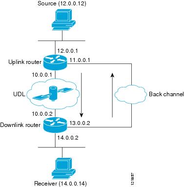
The following example shows how to configure IGMP UDLR. In this example, uplink-rtr is the local upstream router and downlink-rtr is the downstream router. Figure 2 illustrates the example.
Both routers are also connected to each other by a back channel connection. Both routers have two IP addresses: one on the UDL and one on the interface that leads to the back channel. The back channel is any return route and can have any number of routers.
Note
All routers on a UDL must have the same subnet address. If all routers on a UDL cannot have the same subnet address, the upstream router must be configured with secondary addresses to match all the subnets that the downstream routers are attached to.
Figure 2 IGMP Unidirectional Link Routing Example
Uplink Router (uplink-rtr) Configuration
ip multicast-routing!! Interface that source is attached to!interface ethernet 0description Typical IP multicast enabled interfaceip address 12.0.0.1 255.0.0.0ip pim sparse-dense-mode!! Back channel!interface ethernet 1description Back channel which has connectivity to downlink-rtrip address 11.0.0.1 255.0.0.0ip pim sparse-dense-mode!! Unidirectional link!interface serial 0description Unidirectional to downlink-rtrip address 10.0.0.1 255.0.0.0ip pim sparse-dense-modeip igmp unidirectional-linkno keepaliveDownlink Router (downlink-rtr) Configuration
ip multicast-routing!! Interface that receiver is attached to, configure for IGMP reports to be! helpered for the unidirectional interface.!interface ethernet 0description Typical IP multicast-enabled interfaceip address 14.0.0.2 255.0.0.0ip pim sparse-dense-modeip igmp helper-address udl serial 0!! Back channel!interface ethernet 1description Back channel that has connectivity to downlink-rtrip address 13.0.0.2 255.0.0.0ip pim sparse-dense-mode!! Unidirectional link!interface serial 0description Unidirectional to uplink-rtrip address 10.0.0.2 255.0.0.0ip pim sparse-dense-modeip igmp unidirectional-linkno keepaliveIntegrated UDLR Tunnel, IGMP UDLR, and IGMP Proxy: Example
The following example shows how to configure UDLR tunnels, IGMP UDLR, and IGMP proxy on both the upstream and downstream routers sharing a UDL.
Upstream Configuration
ip multicast-routing!interface Tunnel0ip address 9.1.89.97 255.255.255.252no ip directed-broadcasttunnel source 9.1.89.97tunnel mode gre multipointtunnel key 5tunnel udlr receive-only Ethernet2/3!interface Ethernet2/0no ip addressshutdown!! user networkinterface Ethernet2/1ip address 9.1.89.1 255.255.255.240no ip directed-broadcastip pim dense-modeip cgmpfair-queue 64 256 128no cdp enableip rsvp bandwidth 1000 100!interface Ethernet2/2ip address 9.1.95.1 255.255.255.240no ip directed-broadcast!! physical send-only interfaceinterface Ethernet2/3ip address 9.1.92.100 255.255.255.240no ip directed-broadcastip pim dense-modeip nhrp network-id 5ip nhrp server-onlyip igmp unidirectional-linkfair-queue 64 256 31ip rsvp bandwidth 1000 100!router ospf 1network 9.1.92.96 0.0.0.15 area 1!ip classlessip route 9.1.90.0 255.255.255.0 9.1.92.99Downstream Configuration
ip multicast-routing!interface Loopback0ip address 9.1.90.161 255.255.255.252ip pim sparse-modeip igmp helper-address udl Ethernet2/3ip igmp proxy-service!interface Tunnel0ip address 9.1.90.97 255.255.255.252ip access-group 120 outno ip directed-broadcastno ip mroute-cachetunnel source 9.1.90.97tunnel destination 9.1.89.97tunnel key 5tunnel udlr send-only Ethernet2/3tunnel udlr address-resolution!interface Ethernet2/0no ip addressno ip directed-broadcastshutdownno cdp enable!! user networkinterface Ethernet2/1ip address 9.1.90.1 255.255.255.240no ip directed-broadcastip pim sparse-modeip igmp mroute-proxy Loopback0no cdp enable!! Backchannelinterface Ethernet2/2ip address 9.1.95.3 255.255.255.240no ip directed-broadcastno cdp enable!! physical receive-only interfaceinterface Ethernet2/3ip address 9.1.92.99 255.255.255.240no ip directed-broadcastip pim sparse-modeip igmp unidirectional-linkno keepaliveno cdp enable!router ospf 1network 9.1.90.0 0.0.0.255 area 1network 9.1.92.96 0.0.0.15 area 1!ip classlessip route 0.0.0.0 0.0.0.0 9.1.95.1! set rpf to be the physical receive-only interfaceip mroute 0.0.0.0 0.0.0.0 9.1.92.96ip pim rp-address 9.1.90.1!! permit ospf, ping and rsvp, deny othersaccess-list 120 permit icmp any anyaccess-list 120 permit 46 any anyaccess-list 120 permit ospf any anyAdditional References
The following sections provide references related to UDLR.
Related Documents
IP multicast commands: complete command syntax, command mode, command history, defaults, usage guidelines, and examples
Tunnel interfaces
"Implementing Tunnels" module
IGMP and IGMP Proxy
"Customizing IGMP" module
MIBs
•
To locate and download MIBs for selected platforms, Cisco IOS releases, and feature sets, use Cisco MIB Locator found at the following URL:
Technical Assistance
Feature Information for Configuring IP Multicast over Unidirectional Links
Table 1 lists the features in this module and provides links to specific configuration information. Only features that were introduced or modified in Cisco IOS Releases 12.2(1) or later appear in the table.
Not all commands may be available in your Cisco IOS software release. For details on when support for specific commands was introduced, see the command reference documents.
Cisco IOS software images are specific to a Cisco IOS software release, a feature set, and a platform. Use Cisco Feature Navigator to find information about platform support and Cisco IOS software image support. Access Cisco Feature Navigator (http://www.cisco.com/go/fn). You must have an account on Cisco.com. If you do not have an account or have forgotten your username or password, click Cancel at the login dialog box and follow the instructions that appear.
Table 1 Feature Information for Configuring IP Multicast over Unidirectional Links
Any Internet Protocol (IP) addresses used in this document are not intended to be actual addresses. Any examples, command display output, and figures included in the document are shown for illustrative purposes only. Any use of actual IP addresses in illustrative content is unintentional and coincidental.
© 2007 Cisco Systems, Inc. All rights reserved.