Feedback
Table Of Contents
About Network Access Controller
Network Access Controller Features
Maintaining State Across Restarts
Connection-Based and Unconditional Blocking
Blocking with Catalyst Switches
AuthenticationApp Responsibilities
Configuring Authentication on the Sensor
Managing TLS and SSH Trust Relationships
Responsibilities and Components
Summary of IPS 5.0 Applications
System Architecture
This appendix describes the system architecture of IPS 5.0. It contains the following sections:
•
Summary of IPS 5.0 Applications
System Overview
You can install Cisco IPS software on two platforms: the appliances and the modules (refer to Supported Sensors for a list of current appliances and modules).
This section contains the following topics:
System Design
IPS software runs on the Linux operating system. We have hardened the Linux OS by removing unnecessary packages from the OS, disabling unused services, restricting network access, and removing access to the shell.
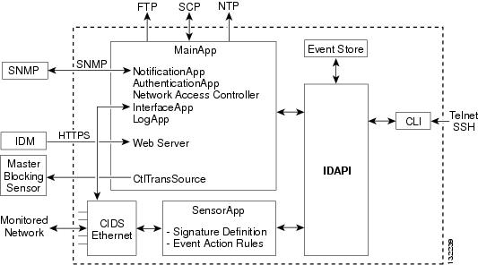
Figure A-1 illustrates the system design:
Figure A-1 System Design
IPS software includes the following applications:
Note
•
–
–
–
–
–
–
–
–
•
•
All IPS applications communicate with each other through a common API called IDAPI. Remote applications (other sensors, management applications, and third-party software) communicate with sensors through RDEP2 and SDEE protocols.
The sensor has the following partitions:
•
•
•
IPS 5.0 New Features
Cisco IPS 5.0 contains the following new features:
•
•
The following applications have been merged in to one application with different threads supporting the old functions: MainApp, Web Server, AuthenticationApp, Network Access Controller, LogApp, and CtlTransSource.
•
You can set the sensor in a mode where all IPS processing subsystems are bypassed and traffic is permitted between the inline pairs directly. The bypass mode ensures that packets continue to flow through the sensor when the sensor's processes are temporarily stopped for upgrades or when the sensor's monitoring processes fail.
•
RR is a value between 0 and 100 that represents a numerical quantification of the risk associated with a particular event on the network. The calculation takes into account the value of the network asset being attacked (for example, a particular server), so it is configured on a per-signature basis (ASR and SFR) and on a per-server basis (TVR).
•
–
–
•
RDEP has been revised to RDEPv2, which supports an event standard called SDEE.
•
ASDM is a browser-based, Java applet used to configure and monitor the software on security appliances. ASDM is loaded from the security appliance, then used to configure, monitor, and manage the device.
•
IDCONF is now the supported method for configuration. It specifies messages for creating, editing, removing, and retrieving configuration data. The older configuration components from IDIOM are no longer supported in IPS 5.0.
•
•
AIC provides deep analysis of web traffic. It provides granular control over HTTP sessions to prevent abuse of the HTTP protocol. It allows administrative control over applications that try to tunnel over specified ports, such as instant messaging, and tunneling applications, such as gotomypc. It can also inspect FTP traffic and control the commands being issued.
•
•
PEP is the UDI information that consists of the PID, VID, and SN of the product.
•
•
The GUI is now a Java applet rather than HTML.
•
IPv4 packets tunneled within IPv6 packets will be processed and have policy enforced on the packet. However, all analysis is done with the IPv4 packet and none of the IPv6 packet information is used.
IPS 5.0 no longer contains the following features:
•
Support for the SYSLOG engine that translates syslog output from routers into IPS alerts has been removed from IPS 5.0. The management stations can now receive and present syslog information.
•
The web-based GUI is replaced by a Java applet.
•
The main configuration XML is now from SDEE.
User Interaction
You interact with IPS 5.0 in the following ways:
•
You generate the initial configuration for the system and its features. This is an infrequent task, usually done only once. The system has reasonable default values to minimize the number of modifications you must make. You can configure IPS 5.0 through the CLI, IDM, IDS MC, ASDM or through another application using RDEP2/IDCONF.
•
You make minor modifications to the configuration, primarily to the Analysis Engine, which is the portion of the application that monitors network traffic. You can tune the system frequently after initially installing it on the network until it is operating efficiently and only producing information you find useful. You can create custom signatures, enable features, or apply a service pack or signature update. You can tune IPS 5.0 through the CLI, IDM, IDS MC, ASDM or through another application using RDEP2/IDCONF.
•
You can schedule automatic updates or apply updates immediately to the applications and signature data files. You can update IPS 5.0 through the CLI, IDM, IDS MC, ASDM or through another application using RDEP2/IDCONF
•
You can retrieve data (status messages, errors, and alarms) from the system through the CLI, IDM, IDS MC, ASDM or another application using RDEP or RDEP2.
Security Features
IPS 5.0 has the following security features:
•
•
•
•
•
•
•
•
MainApp
MainApp now includes all IPS components except SensorApp and the CLI. This section describes MainApp, and contains the following topics:
MainApp Responsibilities
MainApp has the following responsibilities:
•
•
•
•
•
•
•
•
MainApp responds to the show version command by displaying the following information:
•
•
•
•
•
•
•
MainApp also gathers the host statistics.
The following applications are now part of MainApp and are responsible for event storage, management, actions, and communication: Event Store, NotificationApp, CtlTransSource, Network Access Controller, and LogApp.
These applications contain the following new features:
•
Support for SNMP is one of the most significant changes for the management interface of the system. Through SNMP you can obtain standard health and welfare information about the system. Signatures have a new action of SNMP notification that causes an SNMP trap to be sent when the signatures fires.
SNMP version 2 is the only version of SNMP supported.
•
The oldest entries expire in Event Store when there is no more room for new entries. RDEP provides different queries for retrieving just audit data vs. IPS alert data. All RDEP and RDEP2 SDEE queries are supported. All events are stored in SDEE CIDEE format.
•
A new health and welfare type of control transaction is defined in the IDCONF specification. This control transaction reports the status and welfare of the system.
Event Store
This section describes Event Store, and contains the following topics:
About Event Store
Each IPS event is stored in Event Store with a time stamp and a unique, monotonic, ascending ID. This time stamp is the primary key used to index the event into the fixed-size, indexed Event Store. When the circular Event Store has reached its configured size, the oldest event or events are overwritten by the new event being stored. SensorApp is the only application that writes alert events into the Event Store. All applications write log, status, and error events into the Event Store.
The fixed-sized, indexed Event Store allows simple event queries based on the time, type, priority, and a limited number of user-defined attributes. If each event is assigned a priority of low, medium, or high, a single event query can specify a list of desired event types, intrusion event priorities, and a time range.
Table A-1 shows some examples:
The size of the Event Store allows sufficient buffering of the IPS events when the sensor is not connected to an IPS event consumer. Sufficient buffering depends on your requirements and the capabilities of the nodes in use. The oldest events in the circular buffer are replaced by the newest events.
Event Data Structures
The various functional units communicate the following seven types of data:
•
•
•
•
•
•
•
All seven types of data are referred to collectively as IPS data. The six event types—intrusion, error, status, control transaction log, network access, and debug—have similar characteristics and are referred to collectively as IPS events. IPS events are produced by the several different applications that make up the IPS and are subscribed to by other IPS applications. IPS events have the following characteristics:
•
•
Control transactions involve the following types of requests:
•
•
•
•
•
Control transactions have the following characteristics:
•
The request and response may have an arbitrary amount of data associated with them. The response always includes at least a positive or negative acknowledgment.
•
Control transactions are sent by one application instance (the initiator) to another application instance (the responder).
IPS data is represented in XML format as an XML document. The system stores user-configurable parameters in several XML files.
IPS Events
IPS applications generate IPS events to report the occurrence of some stimulus. The events are the data, such as the alerts generated by SensorApp or errors generated by any application. Events are stored in a local database known as the Event Store.
There are five types of events:
•
•
•
•
•
You can view the status and error messages using the CLI, IDM, and ASDM.
SensorApp and Network Access Controller log response actions (TCP resets, IP logging start and stop, blocking start and stop, trigger packet) as status messages.
NotificationApp
NotificationApp allows the sensor to send alerts and system error messages as SNMP traps. It subscribes to events in the Event Store and translates them into SNMP MIBs and sends them to destinations through a public-domain SNMP agent. NotificationApp supports sending sets and gets. The SNMP GETs provide information about basic sensor health.
NotificationApp sends the following information from the <evAlert> event in sparse mode:
•
•
•
•
•
•
•
•
•
NotificationApp sends the following information from the <evAlert> event in detail mode:
•
•
•
•
•
•
•
•
•
•
•
•
•
•
•
•
NotificationApp determines which <evError> events to send as a trap according to the filter that you define. You can filter based on error severity (error, fatal, and warning). NotificationApp sends the following information from the <evError> event:
•
•
•
•
•
NotificationApp supports GETs for the following general health and system information from the sensor:
•
•
•
•
•
•
•
•
•
•
•
•
•
•
•
•
•
•
•
•
•
•
Note
NotificationApp provides the following statistics:
•
•
•
•
CtlTransSource
CtlTransSource is an application that forwards locally initiated remote control transactions to their remote destinations using the RDEP and HTTP protocols. CtlTransSource initiates either TLS or non-TLS connections and communicates remote control transactions to HTTP servers over these connections.
CtlTransSource must establish sufficient credentials on the remote HTTP server to execute a remote control transaction. It establishes its credentials by presenting an identity to the HTTP server on the remote node in the form of a username and password (basic authentication). When the authentication is successful, the requestor is assigned a cookie containing a user authentication that must be presented with each request on that connection.
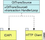
The transactionHandlerLoop method in the CtlTransSource serves as a proxy for remote control transaction. When a local application initiates a remote control transaction, IDAPI initially directs the transaction to CtlTransSource. The transactionHandlerLoop method is a loop that waits on remote control transactions that are directed to CtlTransSource.
Figure A-2 shows the transactionHandlerLoop method in the CtlTransSource.
Figure A-2 CtlTransSource
When the transactionHandlerLoop receives a remotely addressed transaction, it tries to forward the remote control transaction to its remote destination. The transactionHandlerLoop formats the transaction into an RDEP control transaction message. The transactionHandlerLoop uses the HttpClient classes to issue the RDEP control transaction request to the HTTP server on the remote node. The remote HTTP server handles the remote control transaction and returns the appropriate RDEP response message in an HTTP response. If the remote HTTP server is an IPS web server, the web server uses the CtlTransSource servlet to process the remote control transactions.
The transactionHandlerLoop returns either the RDEP response or a failure response as the control transaction's response to the remote control transaction's initiator. If the HTTP server returns an unauthorized status response (indicating the HTTP client has insufficient credentials on the HTTP server), the transactionHandlerLoop reissues the transaction request using CtlTransSource's designated username and password to authenticate the requestor's identity. The transactionHandlerLoop continues to loop until it receives a control transaction that directs it to exit or until its exit event is signaled.
Network Access Controller
This section describes Network Access Controller, which is the IPS application that starts and stops blocks on routers, switches, and firewalls. A block is an entry in a device's configuration or ACL to block incoming and outgoing traffic for a specific host IP address or network address.
This section contains the following topics:
•
•
•
•
•
•
About Network Access Controller
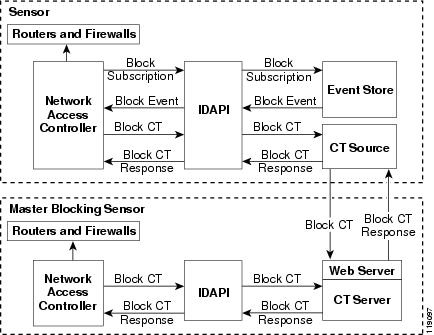
Network Access Controller's main responsibility is to block events. When it responds to a block, it either interacts with the devices it is managing directly to enable the block or it sends a block request through the Control Transaction Server to a master blocking sensor. The Web Server on the master blocking sensor receives the control transaction and passes it to the Control Transaction Server, which passes it to the Network Access Controller. Network Access Controller on the master blocking sensor then interacts with the devices it is managing to enable the block.
Figure A-3 illustrates Network Access Controller.
Figure A-3 Network Access Controller
Note
Network Access Controller initiates a block in response to one of the following:
•
•
•
When you configure Network Access Controller to block a device, it initiates either a Telnet or SSH connection with the device. Network Access Controller maintains the connection with each device. After the block is initiated, Network Access Controller pushes a new set of configurations or ACLs (one for each interface direction) to each controlled device. When a block is completed, all configurations or ACLs are updated to remove the block.
Network Access Controller Features
Network Access Controller has the following features:
•
Only the protocol specified in the Network Access Controller configuration for that device is attempted. If the connection fails for any reason, Network Access Controller attempts to reestablish it.
•
If a preexisting ACL exists on a router interface or direction that is controlled by Network Access Controller, you can specify that this ACL be merged into the Network Access Controller-generated configuration, either before any blocks by specifying a preblock ACL or after any blocks by specifying a postblock ACL. The Catalyst 6000 VACL device types can have a preblock and postblock VACL specified for each interface that Network Access Controller controls. The firewall device types use a different API to perform blocks and Network Access Controller does not have any effect on preexisting ACLs on the firewalls.
Note
For more information, see ACLs and VACLs.
•
Network Access Controller can forward blocks to a list of remote sensors, so that multiple sensors can in effect collectively control a single network device. Such remote sensors are referred to as master blocking sensors. For more information on master blocking sensors, see Configuring the Master Blocking Sensor.
•
You can specify the interface and direction where blocking is performed in the Network Access Controller configuration for routers. You can specify the interface where blocking is performed in the VACL configuration.
Note
Network Access Controller can simultaneously control up to 250 interfaces.
•
Network Access Controller can block a host or network for a specified number of minutes or indefinitely. Network Access Controller determines when a block has expired and unblocks the host or network at that time.
•
Network Access Controller writes a confirmation event when block or unblock actions are completed successfully or if any errors occur. Network Access Controller also logs important events such as loss and recovery of a network device communication session, configuration errors, and errors reported by the network device.
•
Network Access Controller reapplies blocks that have not expired when a shutdown or restart occurs. Network Access Controller removes blocks that have expired while it was shut down.
Note
For more information, see Maintaining State Across Restarts.
•
Network Access Controller reapplies blocks and removes expired blocks as needed whenever a network device is shut down and restarted. Network Access Controller is not affected by simultaneous or overlapping shutdowns and restarts of Network Access Controller.
•
Network Access Controller can establish a communications session with a network device that uses AAA authentication and authorization including the use of remote TACACS+ servers.
•
Network Access Controller supports host blocks and network blocks. Host blocks are connection based or unconditional. Network blocks are always unconditional.
For more information, see Connection-Based and Unconditional Blocking.
•
Network Access Controller can control network devices that use a NAT address for the sensor. If you specify a NAT address when you configure a network device, that address is used instead of the local IP address when the sensor address is filtered from blocks on that device.
•
Network Access Controller does not share control of network devices with administrators or other software. If you must update a configuration, shut down Network Access Controller until the change is complete. You can enable or disable Network Access Controller through the CLI or any IPS manager. When Network Access Controller is reenabled, it completely reinitializes itself, including rereading the current configuration for each controlled network device.
Note
•
Network Access Controller can maintain up to 250 active blocks at a time. Although Network Access Controller can support up to 65535 blocks, we recommend that you allow no more than 250 at a time.
Note
Supported Blocking Devices
Network Access Controller can control the following devices:
•
•
Note
•
•
•
•
Note
ACLs and VACLs
If you want to filter packets on an interface or direction that Network Access Controller controls, you can configure Network Access Controller to apply an ACL before any blocks (preblock ACL) and to apply an ACL after any blocks (postblock ACL). These ACLs are configured on the network device as inactive ACLs. You can define preblock and postblock ACLs for each interface and direction. Network Access Controller retrieves and caches the lists and merges them with the blocking ACEs whenever it updates the active ACL on the network device. In most cases, you will want to specify a preexisting ACL as the postblock ACL so that it does not prevent any blocks from taking effect. ACLs work by matching a packet to the first ACE found. If this first ACE permits the packet, a subsequent deny statement will not be found.
You can specify different preblock and postblock ACLs for each interface and direction, or you can reuse the same ACLs for multiple interfaces and directions. If you do not want to maintain a preblock list, you can use the never block option and always block hosts and networks by using existing configuration statements. A forever block is a normal block with a timeout value of -1.
Network Access Controller only modifies ACLs that it owns. It does not modify ACLs that you have defined. The ACLs maintained by Network Access Controller have a specific format that should not be used for user-defined ACLs. The naming convention is IPS_interface_name_[in | out]_[0 | 1]. interface_name corresponds to the name of the blocking interface as given in the Network Access Controller configuration.
For Catalyst switches, it is a blocking interface VLAN number. Do not use these names for preblock and postblock ACLs.
For Catalyst 6000 VACLs, you can specify a preblock and postblock VACL and only the interface is specified (direction is not used in VLANs).
For firewalls, you cannot use preblock or postblock ACLs because the firewall uses a different API for blocking. Instead you must create ACLs directly on the firewalls. For more information, see Blocking with Cisco Firewalls.
Maintaining State Across Restarts
When the blocked host list or blocked network list changes, the new lists (with starting timestamps) are written to a local file (nac.shun.txt) that is maintained by Network Access Controller. When Network Access Controller starts, this file is used to determine if any block updates should occur at the controlled network devices. Any unexpired blocks found in the file are applied to the network devices at startup. When Network Access Controller shuts down, no special actions on the ACLs are taken even if outstanding blocks are in effect. The nac.shun.txt file is accurate only if the system time is not changed while Network Access Controller is not running.
Caution
The following scenarios demonstrate how Network Access Controller maintains state across restarts.
Scenario 1
There are two blocks in effect when Network Access Controller stops and one of them expires before Network Access Controller restarts. When Network Access Controller restarts, it first reads the nac.shun.txt file. It then reads the preblock and postblock ACLs or VACLs. The active ACL or VACL is built in the following order:
1.
2.
3.
4.
5.
When a host is specified as never block in the Network Access Controller configuration, it does not get translated into permit statements in the ACL. Instead, it is cached by Network Access Controller and used to filter incoming addShunEvent events and addShunEntry control transactions.
Scenario 2
There are no preblock or postblock ACLs specified, but there is an existing active ACL. The new ACL is built in the following order:
1.
2.
3.
4.
Connection-Based and Unconditional Blocking
Network Access Controller supports two types of blocking for hosts and one type of blocking for networks. Host blocks are connection-based or unconditional. Network blocks are always unconditional.
When a host block is received, Network Access Controller checks for the connectionShun attribute on the host block. If connectionShun is set to true, Network Access Controller performs connection blocking. Any host block can contain optional parameters, such as destination IP address, source port, destination port, and protocol. For a connection block to take place, at least the source IP address must be present.
Under the following conditions, Network Access Controller forces the block to be unconditional, converting the block from connection type if necessary:
•
•
•
When a block is updated (for example, when a new block arrives while an existing block for that source IP address or network is already in effect), the remaining minutes of the existing block are determined. If the time for the new block is less than or equal to the remaining minutes, no action is taken. Otherwise, the new block timeout replaces the existing block timeout.
Caution
Blocking with Cisco Firewalls
Network Access Controller performs blocks on firewalls using the shun command. The shun command has the following formats:
•
shun srcip [destination_ip_address source_port destination_port [port]]
•
no shun ip
•
clear shun
•
show shun [ip_address]
Network Access Controller uses the response to the show shun command to determine whether the block was performed.
The shun command does not replace existing ACLs, conduits, or outbound commands, so there is no need to cache the existing firewall configuration, nor to merge blocks into the firewall configuration.
Caution
If the block command specifies only the source IP address, existing active TCP connections are not broken, but all incoming packets from the blocked host are dropped.
When Network Access Controller first starts up, the active blocks in the firewall are compared to an internal blocking list. Any blocks that do not have a corresponding internal list entry are removed.
For more information, see Configuring Blocking Devices.
Network Access Controller supports authentication on a firewall using local usernames or a TACACS+ server. If you configure the firewall to authenticate using AAA but without the TACACS+ server, Network Access Controller uses the reserved username pix for communications with the firewall.
If the firewall uses a TACACS+ server for authentication, you use a TACACS+ username. In some firewall configurations that use AAA logins, you are presented with three password prompts: the initial firewall password, the AAA password, and the enable password. Network Access Controller requires that the initial firewall password and the AAA password be the same.
When you configure a firewall to use NAT or PAT and the sensor is checking packets on the firewall outside network, if you detect a host attack that originates on the firewall inside network, the sensor tries to block the translated address provided by the firewall. If you are using dynamic NAT addressing, the block can be ineffective or cause innocent hosts to be blocked. If you are using PAT addressing, the firewall could block the entire inside network. To avoid these situations, position your sensor on the inside interface or do not configure the sensor to block.
Blocking with Catalyst Switches
Catalyst switches with a PFC filter packets using VACLs. VACLs filter all packets between VLANs and within a VLAN.
MSFC router ACLs are supported when WAN cards are installed and you want the sensor to control the interfaces through the MSFC2.
Note
Caution
The following commands apply to the Catalyst VACLs:
•
show security acl info acl_name
•
set security acl ip acl_name deny address_spec
•
commit security acl all
•
clear security acl map acl_name
•
clear security acl map all
•
set sec acl acl_name vlans
For more information, see Configuring Blocking Devices.
LogApp
The sensor logs all events (alert, error, status, and debug messages) in a persistent, circular buffer. The sensor also generates IP logs. The messages and IP logs are accessible through the CLI, IDM, ASDM, and RDEP clients.
The IPS applications use LogApp to log messages. LogApp sends log messages at any of five levels of severity: debug, timing, warning, error, and fatal. LogApp writes the log messages to /usr/cids/idsRoot/log/main.log, which is a circular text file. New messages overwrite older messages when the file reaches its maximum size, therefore the last message written may not appear at the end of the main.log. Search for the string "= END OF FILE =" to locate the last line written to the main.log.
The main.log is included in the show tech-support command output. If the message is logged at warning level or above (error or fatal), LogApp converts the message to an evError event (with the corresponding error severity) and inserts it in Event Store.
Note
LogApp receives all syslog messages, except cron messages, that are at the level of informational and above (*.info;cron.none), and inserts them into Event Store as <evErrors> with the error severity set to Warning. LogApp and application logging are controlled through the service logger commands.
LogApp can control what log messages are generated by each application by controlling the logging severity for different logging zones. You would only access the individual-zone-control of the logger service at the request and supervision of a TAC engineer or developer. For troubleshooting purposes, TAC might request that you turn on debug logging. For more information, see Enabling Debug Logging.
AuthenticationApp
This section describes AuthenticationApp, and contains the following topics:
•
•
•
AuthenticationApp Responsibilities
AuthenticationApp has the following responsibilities:
•
•
•
Authenticating Users
You must configure authentication on the sensor to establish appropriate security for user access. When you install a sensor, an initial cisco account with an expired password is created. A user with administrative access to the sensor accesses the sensor through the CLI or an IPS manager, such as IDM or ASDM, by logging in to the sensor using the default administrative account (cisco). In the CLI, the Administrator is prompted to change the password. IPS managers initiate a setEnableAuthenticationTokenStatus control transaction to change the account's password.
Through the CLI or an IPS manager, the Administrator configures which authentication method is used, such as username and password or an SSH authorized key. The application servicing the Administrator initiates a setAuthenticationConfig control transaction to establish the authentication configuration.
The authentication configuration includes a login attempt limit value that is used to specify how account locking is handled. Account locking is invoked when the number of consecutive failed login attempts for a given account exceeds the login attempt limit value. After an account is locked, all further attempts to log in to that account are rejected. The account is unlocked by resetting the account's authentication token using the setEnableAuthenticationTokenStatus control transaction. The account locking feature is disabled when the login attempt limit value is set to zero.
The Administrator can add additional user accounts either through the CLI or an IPS manager. For more information, see User Roles.
Configuring Authentication on the Sensor
When a user tries to access the sensor through a service such as Web Server or the CLI, the user's identity must be authenticated and the user's privileges must be established. The service that is providing access to the user initiates an execAuthenticateUser control transaction request to AuthenticationApp to authenticate the user's identity. The control transaction request typically includes the username and a password, or the user's identity can be authenticated using an SSH authorized key.
AuthenticationApp responds to the execAuthenticateUser control transaction request by attempting to authenticate the user's identity. AuthenticationApp returns a control transaction response that contains the user's authentication status and privileges. If the user's identity cannot be authenticated, AuthenticationApp returns an unauthenticated status and anonymous user privileges in the control transaction response. The control transaction response also indicates if the account's password has expired. User interface applications that authenticate users by initiating an execAuthenticateUser control transaction prompt the user to change the password.
AuthenticationApp uses the underlying operating system to confirm a user's identity. All the IPS applications send control transactions to AuthenticationApp, which then uses the operating system to form its responses.
Remote shell services, Telnet and SSH, are not IPS applications. They call the operating system directly. If the user is authenticated, it launches the IPS CLI. In this case, the CLI sends a special form of the execAuthenticateUser control transaction to determine the privilege level of the logged-in user. The CLI then tailors the commands it makes available based on this privilege level.
Managing TLS and SSH Trust Relationships
Encrypted communications over IP networks provide data privacy by making it impossible for a passive attacker to discover from the packets exchanged alone the secret key needed to decrypt the data in the packets.
However, an equally dangerous attack vector is for an imposter to pretend to be the server end of the connection. All encryption protocols provide a means for clients to defend themselves from these attacks. IPS supports two encryption protocols, SSH and TLS, and AuthenticationApp helps manage trust when the sensor plays either the client or server role in encrypted communications.
The IPS Web Server and SSH server are server endpoints of encrypted communications. They protect their identities with a private key and offer a public key to clients that connect to them. For TLS this public key is included inside an X.509 certificate, which includes other information. Remote systems that connect to the sensor should verify that the public key received during connection establishment is the key they expect.
Clients must maintain a list of trusted public keys to protect themselves from man-in-the-middle attacks. The exact procedure by which this trust is established varies depending on the protocol and client software. In general, the client displays a fingerprint of 16 or 20 bytes. The human operator who is configuring the client to establish trust should use an out-of-band method to learn the server's key fingerprints before attempting to establish trust. If the fingerprints match, the trust relationship is established and henceforth the client can automatically connect with that server and be confident that the remote server is not an imposter.
You can use the show ssh server-key and show tls fingerprint to display the sensor's key fingerprints. By recording the output of these commands when directly connected to the sensor console, you can reliably use this information to confirm the sensor's identity over the network later when establishing trust relationships.
For example, when you initially connect to a sensor through the Microsoft Internet Explorer web browser, a security warning dialog box indicates that the certificate is not trusted. Using Internet Explorer's user interface, you can inspect the certificate thumbprint, a value that should exactly match the SHA1 fingerprint displayed by the show tls fingerprint command. After verifying this, add this certificate to the browser's list of trusted CAs to establish permanent trust.
Each TLS client has different procedures for establishing this trust. The sensor itself includes a TLS client that is used to send control transactions to other sensors and download upgrades and configuration files from other TLS web servers. Use the tls trusted-host command to establish trust of the TLS servers with which the sensor communicates.
Similarly, the sensor includes an SSH client that is used to communicate with managed network devices, download upgrades, and copy configurations and support files to remote hosts. Use the ssh host-key command to establish trust relationships with the SSH servers the sensor will contact.
You can manage the list of TLS trusted certificates and SSH known hosts through the commands service trusted-certificates and service ssh-known-hosts.
X.509 certificates include additional information that can increase the security of the trust relationship; however, these can lead to confusion. For example, an X.509 certificate includes a validity period during which the certificate can be trusted. Typically this period is a number of years starting at the moment the certificate is created. To ensure that an X.509 certificate is valid at the moment it is being used requires that the client system maintain an accurate clock.
X.509 certificates are also tied to a particular network address. Sensors fill this field with the IP address of the sensor's command and control interface. Consequently, if you change the command and control IP address of the sensor, the server's X.509 certificate is regenerated. You must reconfigure all clients on the network that trusted the old certificate to locate the sensor at its new IP address and trust the new certificate.
By using the SSH known hosts and TLS trusted certificates services in AuthenticationApp, you can operate sensors at a high level of security.
Web Server
Web Server provides RDEP2 support, which enables the sensor to report security events, receive IDIOM transactions, and serve IP logs.
Web Server supports HTTP 1.0 and 1.1. Communications with Web Server often include sensitive information, such as passwords, that would severely compromise the security of the system if an attacker were able to eavesdrop. For this reason, sensors ship with TLS enabled. The TLS protocol is an encryption protocol that is compatible with SSL.
SensorApp
This section describes SensorApp, and contains the following topics:
•
•
Responsibilities and Components
SensorApp performs packet capture and analysis. Policy violations are detected through signatures in SensorApp and the information about the violations is forwarded to the Event Store in the form of an alert.
Packets flow through a pipeline of processors fed by a producer designed to collect packets from the network interfaces on the sensor.
SensorApp supports the following processors:
•
This processor processes events stored in a time-slice calendar. Its primary task is to make stale database entries expire and to calculate time-dependent statistics.
•
This processor handles the deny attacker functions. It maintains a list of denied source IP addresses. Each entry in the list expires based on the global deny timer, which you can configure in the virtual sensor configuration.
•
This processor processes event actions. It supports the following event actions:
–
–
–
–
–
–
–
–
–
–
Event actions can be associated with an event RR threshold that must be surpassed for the actions to take place.
•
This processor keeps track of system statistics such as packet counts and packet arrival rates.
•
This processor processes layer 2-related events. It also identifies malformed packets and removes them from the processing path. You can configure actionable events for detecting malformed packets such as alert, capture packet, and deny packet. The layer 2 processor updates statistics about packets that have been denied because of the policy you have configured.
•
This processor maintains the signature state and flow databases.
•
This processor reassembles fragmented IP datagrams. It is also responsible for normalization of IP fragments when the sensor is in inline mode.
•
This processor reorders TCP streams to ensure the arrival order of the packets at the various stream-based inspectors. It is also responsible for normalization of the TCP stream. The normalizer engine lets you enable or disable alert and deny actions.
The TCP SRP normalizer has a hold-down timer, which lets the stream state rebuild after a reconfiguration event. You cannot configure the timer. During the hold-down interval, the system synchronizes stream state on the first packet in a stream that passes through the system. When the hold down has expired, sensorApp enforces your configured policy. If this policy calls for a denial of streams that have not been opened with a 3-way handshake, established streams that were quiescent during the hold-down period will not be forwarded and will be allowed to timeout. Those streams that were synchronized during the hold-down period are allowed to continue.
•
This processor dispatches packets to the inspectors that are not stream-based and that are configured for interest in the packet in process.
•
A process found only on dual CPU systems.
Some of the processors call inspectors to perform signature analysis. All inspectors can call the alarm channel to produce alerts as needed.
SensorApp also supports the following units:
•
The analysis engine handles sensor configuration. It maps the interfaces and also the signature and alarm channel policy to the configured interfaces.
•
The alarm channel processes all signature events generated by the inspectors. Its primary function is to generate alerts for each event it is passed.
Packet Flow
Packets are received by the NIC and placed in the kernel user-mapped memory space by the IPS-shared driver. The packet is prepended by the IPS header. Each packet also has a field that indicates whether to pass or deny the packet when it reaches SEAP.
The producer pulls packets from the shared-kernel user-mapped packet buffer and calls the process function that implements the processor appropriate to the sensor model. The following orders occur:
•
TP --> L2P --> DFP --> FRP --> SP --> DBP --> SAP --> SRP --> EAP
•
Execution Thread 1 TP --> L2P --> DFP --> FRP --> SP --> DBP --> SAP --> SDP --> | Execution Thread 2 DBP --> SRP --> EAP
SEAP
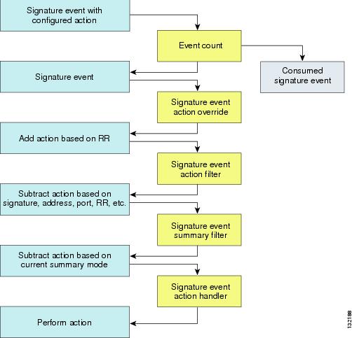
SEAP coordinates the data flow from the signature event in the alarm channel to processing through the SEAO, the SEAF, and the SEAH. It consists of the following components:
•
The unit that represents the area to communicate signature events from the Sensor App inspection path to signature event handling.
•
Adds actions based on the RR value. SEAO applies to all signatures that fall into the range of the configured RR threshold. Each SEAO is independent and has a separate configuration value for each action type. For more information, see Calculating the Risk Rating.
•
Subtracts actions based on the signature event's signature ID, addresses, and RR. The input to the SEAF is the signature event with actions possibly added by the SEAO.
Note
The following parameters apply to the SEAF:
–
–
–
–
–
–
–
–
–
–
–
•
Performs the requested actions. The output from the SEAH is the actions being performed and possibly an <evIdsAlert> written to the Event Store.
Figure A-4 illustrates the logical flow of the signature event through the SEAP and the operations performed on the action for this event. It starts with the signature event with configured action received in the alarm channel and flows top to bottom as the signature event passes through the functional components of the SEAP.
Figure A-4 Signature Event Through SEAP
New Features
SensorApp contains the following new features:
•
When the sensor is processing packets in the data path, all packets are forwarded without any modifications unless explicitly denied by policy configuration. Because of TCP normalization it is possible that some packets will be delayed to ensure proper coverage. When policy violations are encountered, SensorApp allows for the configuration of actions. Additional actions are available in inline mode, such as deny packet, deny flow, and deny attacker.
All packets that are unknown or of no interest to the IPS are forwarded to the paired interface with no analysis. All bridging and routing protocols are forwarded with no participation other than a possible deny due to policy violations. There is no IP stack associated with any interface used for inline (or promiscuous) data processing. The current support for 802.1q packets in promiscuous mode is extended to inline mode.
•
•
•
When SensorApp first starts, it may need to build state information for any flows that currently exist. The hold-down timer prevents SensorApp from denying packets while building this state information. During the hold-down timer, SensorApp still enforces policy whenever there is enough information.
•
Intentional or unintentional fragmentation of IP datagrams can serve to hide exploits making them difficult or impossible to detect. Fragmentation can also be used to circumvent access control policies like those found on firewalls and routers. And different operating systems use different methods to queue and dispatch fragmented datagrams. If the sensor has to check for all possible ways that the end host will reassemble the datagrams, it makes the sensor vulnerable to denial of service attacks. Reassembling all fragmented datagrams inline and only forwarding completed datagrams, refragmenting the datagram if necessary, is the solution to this problem. The IP Fragmentation Normalization unit performs this function.
•
Through intentional or natural TCP session segmentation, some classes of attacks can be hidden. To make sure policy enforcement can occur with no false positives and false negatives, the state of the two TCP endpoints must be tracked and only the data that is actually processed by the real host endpoints should be passed on. Overlaps in a TCP stream can occur, but are extremely rare except for TCP segment retransmits. Overwrites in the TCP session should not occur. If overwrites do occur, someone is intentionally trying to elude the security policy or the TCP stack implementation is broken. Maintaining full information about the state of both endpoints is not possible unless the sensor acts as a TCP proxy. Instead of the sensor acting as a TCP proxy, the segments will be ordered properly and the normalizer will look for any abnormal packets associated with evasion and attacks.
•
The event RR incorporates the following additional information beyond the detection of a potentially malicious action:
–
–
–
–
Event RR helps reduce false positives from the system and gives you more control over what causes an alarm.
•
4.x event filters filtered all actions. 5.0 event filters handle events separately. Sending the alarm is now also considered an action and you can filter or configure it like the other actions.
•
The drivers for the data interfaces support concurrent use of the interfaces by SensorApp and TCPdump or other libpcap based reader
CLI
The CLI provides the sensor user interface for all direct node access such as Telnet, SSH, and serial interface. You configure the sensor applications with the CLI. Direct access to the underlying OS is allowed through the service role.
This section contains the following topics:
User Roles
The CLI for IPS 5.0 permits multiple users to log in at a time. You can create and remove users from the local sensor. You can only modify one user account at a time. Each user is associated with a role that controls what that user can and cannot modify
The CLI supports four user roles: Administrator, Operator, Viewer, and Service. The privilege levels for each role are different; therefore, the menus and available commands vary for each role.
•
–
–
–
–
–
–
–
–
•
–
–
–
–
•
Tip
•
When you log in to the service account, you receive the following warning:
******************************* WARNING *****************************************UNAUTHORIZED ACCESS TO THIS NETWORK DEVICE IS PROHIBITED.This account is intended to be used for support and troubleshooting purposes only. Unauthorized modifications are not supported and will require this device to be re-imaged to guarantee proper operation.*********************************************************************************
Note
Service Account
The service account is a support and troubleshooting tool that enables TAC to log in to a native operating system shell rather than the CLI shell. It does not exist on the sensor by default. You must create it so that it available for TAC to use for troubleshooting your sensor. Refer to "Creating the Service Account," in Configuring the Cisco Intrusion Prevention System Sensor Using the Command Line Interface 5.0 for the procedure to create the service account.
Only one service account is allowed per sensor and only one account is allowed a service role. When the service account's password is set or reset, the root account's password is set to the same password. This allows the service account user to su to root using the same password. When the service account is removed, the root account's password is locked.
The service account is not intended to be used for configuration purposes. Only modifications made to the sensor through the service account under the direction of TAC are supported. Cisco Systems does not support the addition and/or running of an additional service to the operating system through the service account, because it affects proper performance and proper functioning of the other IPS services. TAC does not support a sensor on which additional services have been added.
You can track logins to the service account by checking the log file /var/log/.tac, which is updated with a record of service account logins.
Note
CLI Behavior
Follow these tips when using the IPS CLI:
Prompts
•
•
Help
•
The following example demonstrates the ? function:
sensor#configure ?terminal Configure from the terminalsensor# configure
Note
•
sensor# show c ?% Ambiguous command : "show c"If you enter the token without the space, a selection of available tokens for the completion (with no help description) appears:
sensor#show c?clock configurationsensor# show c•
Tab Completion
•
•
•
Recall
•
Note
•
Case Sensitivity
•
sensor#CONFand press Tab, the sensor displays:
sensor# CONFigureDisplay Options
•
sensor#is an interactive prompt that indicates that the terminal output exceeds the allotted display space. To display the remaining output, press the spacebar to display the next page of output or press Enter to display the output one line at a time.•
Communications
This section describes the communications protocols used by IPS 5.0. It contains the following topics:
•
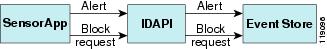
IDAPI
IPS applications use an interprocess communication API called IDAPI to handle internal communications. IDAPI reads and writes event data and provides a mechanism for control transactions. IDAPI is the interface through which all the applications communicate.
SensorApp captures and analyzes the network traffic on its interfaces. When a signature is matched, SensorApp generates an alert, which is stored in the Event Store. If the signature is configured to perform the blocking response action, SensorApp generates a block event, which is also stored in the Event Store.
Figure A-5 illustrates the IDAPI interface.
Figure A-5 IDAPI
Each application registers to the IDAPI to send and receive events and control transactions. IDAPI provides the following services:
•
–
–
–
•
–
–
–
IDAPI provides the necessary synchronization mechanisms to guarantee atomic data accesses.
RDEP2
External communications use RDEP2. RDEP2 is an application-level communications protocol used to exchange IPS event, IP log, configuration, and control messages between IPS clients and IPS servers. RDEP2 communications consist of request and response messages. RDEP2 clients initiate request messages to RDEP2 servers. RDEP2 servers respond to request messages with response messages.
RDEP2 defines three classes of request/response messages: event, IP log, and transaction messages. Event messages include IPS alert, status, and error messages. Clients use IP log requests to retrieve IP log data from servers. Transaction messages are used to configure and control IPS servers.
RDEP2 uses the industry standards HTTP, TLS and SSL and XML to provide a standardized interface between RDEP2 agents. The RDEP2 protocol is a subset of the HTTP 1.1 protocol. All RDEP2 messages are legal HTTP 1.1 messages. RDEP2 uses HTTP's message formats and message exchange protocol to exchange messages between RDEP2 agents.
You use the IPS manager to specify which hosts are allowed to access the sensor through the network. Sensors accept connections from 1 to 10 RDEP2 clients simultaneously. Clients selectively retrieve data by time range, type of event (alert, error, or status message) and level (alert = high, medium, low, or informational; error = high, medium, low). Events are retrieved by a query (a single bulk get) or subscription (a real-time persistent connection) or both. Communications are secured by TLS or SSL.
Note
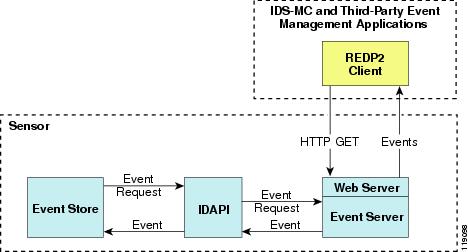
Remote applications retrieve events from the sensor through RDEP2. The remote client sends an RDEP2 event request to the sensor's Web Server, which passes it to the Event Server. The Event Server queries the Event Store through IDAPI and then returns the result.
Figure A-6 shows remote applications retrieving events from the sensor through RDEP2.
Figure A-6 Retrieving Events Through RDEP2
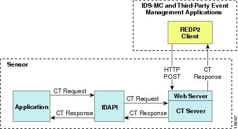
Remote applications send commands to the sensor through RDEP2. The remote client sends an RDEP2 control transaction to the sensor's Web Server, which passes it to the Control Transaction Server. The Control Transaction Server passes the control transaction through IDAPI to the appropriate application, waits for the application's response, and then returns the result.
Figure A-7 shows remote applications sending commands to the sensor through RDEP2.
Figure A-7 Sending Commands Through RDEP2
IDIOM
IDIOM is a data format standard that defines the event messages that are reported by the IPS as well as the operational messages that are used to configure and control intrusion detection systems. These messages consist of XML documents that conform to the IDIOM XML schema.
IDIOM supports two types of interactions: event and control transaction. Event interactions are used to exchange IPS events such as alerts. IDIOM uses two types of messages for event interactions: event and error messages. Control transactions provide a means for one host to initiate an action in, change the state of, or read the state of another host. Control transactions utilize four types of IDIOM messages: request, response, configuration, and error messages. Events and control transactions that are communicated between application instances within a host are known as local events or local control transactions, or collectively, local IDIOM messages. Events and control transactions that are communicated between different hosts using the RDEP2 protocol are known as remote events and remote control transactions, or collectively, remote IDIOM messages.
Note
IDCONF
IPS 5.0 manages its configuration using XML documents. IDCONF specifies the XML schema including IPS 5.0 control transactions. The IDCONF schema does not specify the contents of the configuration documents, but rather the framework and building blocks from which the configuration documents are developed. It provides mechanisms that let the IPS managers and CLI ignore features that are not configurable by certain platforms or functions through the use of the feature-supported attribute.
IDCONF messages are exchanged over RDEP2 and are wrapped inside IDIOM request and response messages.
The following is an IDCONF example:
<?xml version="1.0" encoding="UTF-8" standalone="yes"?><request xmlns="http://www.cisco.com/cids/idiom" schemaVersion="2.00"><editConfigDelta xmlns="http://www.cisco.com/cids/idconf"><component name="userAccount"><config typedefsVersion="2004-03-01" xmlns="http://www.cisco.com/cids/idconf"><struct><map name="user-accounts" editOp="merge"><mapEntry><key><var name="name">cisco</var></key><struct><struct name="credentials"><var name="role">administrator</var></struct></struct></mapEntry></map></struct></config></component></editDefaultConfig></request>SDEE
IPS produces various types of events including intrusion alerts and status events. IPS communicates events to clients such as management applications using the proprietary RDEP2. We have also developed an IPS-industry leading protocol, SDEE, which is a product-independent standard for communicating security device events. SDEE is an enhancement to the current version of RDEP2 that adds extensibility features that are needed for communicating events generated by various types of security devices.
Systems that use SDEE to communicate events to clients are referred to as SDEE providers. SDEE specifies that events can be transported using the HTTP or HTTP over SSL and TLS protocols. When HTTP or HTTPS is used, SDEE providers act as HTTP servers, while SDEE clients are the initiators of HTTP requests.
IPS includes Web Server, which processes HTTP or HTTPS requests. Web Server uses run-time loadable servlets to process the different types of HTTP requests. Each servlet handles HTTP requests that are directed to the URL associated with the servlet. The SDEE server is implemented as a web server servlet.
The SDEE server only processes authorized requests. A request is authorized if is originates from a web server to authenticate the client's identity and determine the client's privilege level.
CIDEE
CIDEE specifies the extensions to SDEE that are used by the Cisco IPS. The CIDEE standard specifies all possible extensions that are supported by IPS. Specific systems may implement a subset of CIDEE extensions. However, any extension that is designated as being required MUST be supported by all systems.
CIDEE specifies the IPS-specific security device events as well as the IPS extensions to SDEE's <evIdsAlert> element.
CIDEE supports the following events:
•
Generated by the CIDEE provider when the provider detects an error or warning condition. The <evError> event contains error code and textual description of the error.
•
Generated by CIDEE providers to indicate that something of potential interest occurred on the host. Different types of status messages can be reported in the status event—one message per event. Each type of status message contains a set of data elements that are specific to the type of occurrence that the status message is describing. The information in many of the status messages may be useful for audit purposes. Errors and warnings are not considered status information and are reported using <evError> rather than <evStatus>.
•
Generated to indicate that a block action is to be initiated by the service that handles network blocking.
The following is a CDIEE extended event example:
<sd:events xmlns:cid="http://www.cisco.com/cids/2004/04/cidee"
xmlns:sd="http://example.org/2003/08/sdee">
<sd:evIdsAlert eventId="1042648730045587005" vendor="Cisco" severity="medium"><sd:originator><sd:hostId>Beta4Sensor1</sd:hostId><cid:appName>sensorApp</cid:appName><cid:appInstanceId>8971</cid:appInstanceId></sd:originator><sd:time offset="0" timeZone="UTC">1043238671706378000</sd:time><sd:signature description="IOS Udp Bomb" id="4600" cid:version="S37"><cid:subsigId>0</cid:subsigId></sd:signature>...IPS 5.0 File Structure
IPS 5.0 has the following directory structure:
•
•
•
•
•
•
•
•
•
•
•
•
•
•
•
•
•
•
•
•
•
•
•
Summary of IPS 5.0 Applications
Table A-2 gives a summary of the applications that make up the IPS.
Table A-2 Summary of Applications
AuthenticationApp
Authorizes and authenticates users based on IP address, password, and digital certificates.
CLI
Accepts command line input and modifies the local configuration using IDAPI.
Event Server1
Accepts RDEP2 request for events from remote clients.
MainApp
Reads the configuration and starts applications, handles starting and stopping of applications and node reboots, handles software upgrades.
InterfaceApp
Handles bypass and physical settings and defines paired interfaces. Physical settings are speed, duplex, and administrative state.
LogApp
Writes all the application's log messages to the log file and the application's error messages to the Event Store.
Network Access Controller
A Network Access Controller is run on every sensor. Each Network Access Controller subscribes to network access events from its local Event Store. The Network Access Controller configuration contains a list of sensors and the network access devices that its local Network Access Controller controls. If a Network Access Controller is configured to send network access events to a master blocking sensor, it initiates a network access control transaction to the remote Network Access Controller that controls the device. These network access action control transactions are also used by IPS managers to issue occasional network access actions.
NotificationApp
Sends SNMP traps when triggered by alert, status, and error events. NotificationApp uses the public domain SNMP agent. SNMP GETs provide information about the general health of the sensor.
SensorApp
Captures and analyzes traffic on the monitored network and generates intrusion and network access events. Responds to IP logging control transactions that turn logging on and off and that send and delete IP log files.
Control Transaction Server2
Accepts control transactions from a remote RDEP2 client, initiates a local control transaction, and returns the response to the remote client.
Control Transaction Source3
Waits for control transactions directed to remote applications, forwards the control transactions to the remote node using RDEP2, and returns the response to the initiator.
IDM
The Java applet that provides an HTML IPS management interface.
Web Server
Waits for remote HTTP client requests and calls the appropriate servlet application.
1 This is a web server servlet.
2 This is a web server servlet.
3 This is a remote control transaction proxy.